
![]()
How to Replace Fuses: 2022 Cadillac XT4 Fuse Box Diagram
The 2022 Cadillac XT4’s fuse box is an important part of making sure that many electrical parts work properly. To keep and fix electrical problems in your car, you need to know how to read the fuse box diagram. Whether it’s a broken radio, a power window that won’t work, or an accessory that won’t work, knowing how to find and change blown fuses can save you time and money on repairs that aren’t needed. This guide will show you how to safely replace fuses in your Cadillac XT4 where to find the fuse box and how to read the picture. This will give you the confidence and skills to handle electrical problems on your own.
2023 Cadillac XT4 Specs, Price, Features, Mileage And Torque (Review)
Electrical System
Electrical System Overload
The vehicle has fuses and circuit breakers to protect against an electrical system overload. When the current electrical load is too heavy, the circuit breaker opens and closes, protecting the circuit until the current load returns to normal or the problem is fixed. This greatly reduces the chance of circuit overload and fire caused by electrical problems.
Fuses and circuit breakers protect power devices in the vehicle.
If there is a problem on the road and a fuse needs to be replaced, the same amperage fuse can be borrowed. Choose some feature of the vehicle that is not needed to use and replace it as soon as possible.
To check a fuse, look at the band inside the fuse. If the band is broken or melted, replace the fuse. Be sure to replace a bad fuse with a fuse of identical size and rating.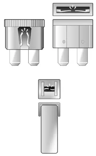
Replacing a Blown Fuse
- Turn off the vehicle.
- Locate the fuse puller in the engine compartment fuse block.

- Use the fuse puller to remove the fuse from the top or side, as shown above.
- If the fuse must be replaced immediately, borrow a replacement fuse with the same amperage from the fuse block. Choose a vehicle feature that is not needed to safely operate the vehicle. Repeat Steps 2-3.
- Insert the replacement fuse into the empty slot of the blown fuse.
At the next opportunity, see your dealer to replace the blown fuse.
Headlamp Wiring
An electrical overload may cause the lamps to go on and off, or in some cases to remain off. Have the headlamp wiring checked right away if the lamps go on and off or remain off?
Windshield Wipers
If the wiper motor overheats due to heavy snow or ice, the windshield wipers will stop. The wiper function is available immediately after the wiper switch is set to off, and back to on. To protect the wiper motor from overheating, the wipers may slow down when the windshield is dry for a long period. If a period of dry operation, or little moisture, exceeds 10 minutes, the wipers may switch to intermittent operation, and remain there. When moisture is again detected on the windshield, wiper operation will return to the operator-selected speed.
Although the circuit is protected from electrical overload, overload due to heavy snow or ice may cause wiper linkage damage. Always clear ice and heavy snow from the windshield before using the windshield wipers.
If the overload is caused by an electrical problem and not snow or ice, be sure to get it fixed.
Fuses and Circuit Breakers
The wiring circuits in the vehicle are protected from short circuits by a combination of fuses and circuit breakers. This greatly reduces the chance of damage caused by electrical problems.
Danger
Fuses and circuit breakers are marked with their ampere rating. Do not exceed the specified amperage rating when replacing fuses and circuit breakers. The use of an oversized fuse or circuit breaker can result in a vehicle fire. You and others could be seriously injured or killed.
Warning
Installation or use of fuses that do not meet GM’s original fuse specifications is dangerous. The fuses could fail, and result in a fire. You or others could be injured or killed, and the vehicle could be damaged.
Engine Compartment Fuse Block
The underhood fuse block is in the engine compartment, on the driver’s side of the vehicle.
Caution
Do not pull the engine compartment fuse block lever, since it is intended only for service purposes. If pulled, vehicle malfunction may occur.
Caution
Spilling liquid on any electrical component of the vehicle may damage it. Always keep the covers on any electrical component.
To remove the fuse block cover, press the clips on the cover and lift it straight up.
The vehicle may not be equipped with all of the fuses, relays, and features shown.
| Fuses | Usage |
| 3 | EBCM – Electronic Brake Control Module |
| 5 | Trailer Brake – Not Used |
| 6 | REAR CLOSR – Spare |
| 7 | TRLR ST/TRN LT – Left Trailer Stop/ Turn Lamp |
| – | |
| 8 | MSM – Memory Seat Module – Driver and Passenger |
| 9 | PFAF – Not Used |
| 10 | SADS – Semi-active Damping System/ Spare |
| – | |
| 11 | DC-DC BAT 1/2 – Direct Current to Direct Current Converter 1 |
| 12 | REAR DEFOG – Rear Window Defogger |
| 13 | HTD MIR – Outside Rear View Mirrors Defogger |
| 14 | – |
| 15 | PEPS – Passive Entry Passive Start Module |
| 16 | FRT/WPR – Front Wiper |
| 17 | PASS/PWR/SEAT – Passenger Power Seat |
| – | |
| 18 | LGM MTR – Power Liftgate |
| 19 | DRVR/PWR/SEAT – Driver Power Seat/ Memory Seat Module/ Driver Seat Massage Control |
| 21 | S/ROOF – Power Sunroof |
| – | |
| 22 | – |
| 23 | TIM 2 – Not Used |
| 26 | TCM IGN – Transmission Control Module/Ignition |
| 27 | IP BODY IGN – Inside Rear View Mirror –Shifter Interface Board Module Run/Crank – Central Gateway Module Run/Crank – Heating Ventilation and Air Conditioning Control Module Run/Crank ignition 3 |
| 28 | RR/WPR – Rear Wiper |
| 29 | TRAILER IGN – Not Used |
| 30 | MIL SS/TIM IGN – Fuel Tank Zone Module Run/Crank – Direct Current to Direct Current Transformer Run/ Crank – Electronic Brake Control Module Run/Crank – Instrument Panel Cluster Run/Crank |
| 32 | RDCM 1 – Rear Drive Control Module 1 |
| – | |
| 33 | FRT HTD ST 2/Spare – Front Heated Seat Power 2/Spare |
| – | |
| 34 | HANDSFREE/WDO SW – Liftgate Module/Front Window Switches |
| 35 | DEFC 2/NOT USED –/Not Used |
| 36 | FUEL MODULE – Fuel Tank Zone Module |
| 39 | MASGE – Driver Seat Massage/Passenger Seat Massage |
| – | |
| 40 | STR/COL/LCK – Spare |
| 41 | – |
| 43 | HTD/STR/WHL – Heated Steering Wheel/Spare |
| – | |
| 44 | FRT HTD 1 & VENT ST – Front Heated Seat Power Feed 1/ Front Vented Seats/ Rear Heated Seats/ Spare |
| – | |
| 46 | ECM IGN – Engine Control Module Ignition |
| 48 | RDCM 2 – Rear Drive Control Module 2/ Spare |
| – | |
| 49 | HVAC BLOWR MTR – Heating Ventilation and Air Conditioning Control Blower Motor |
| 50 | Spare |
| 51 | Spare |
| 54 | Spare |
| 55 | Spare |
| 56 | STRTR MTR – Starter Motor |
| 57 | – |
| 58 | – |
| 59 | HDLP HI BEAM LT/ RT – High Beam Headlamps |
| 60 | TIM 1 – Not Used |
| 61 | Spare |
| 62 | Spare |
| 63 | Spare |
| 65 | A/C CLUTCH – Air Conditioning Clutch |
| 67 | Spare |
| 68 | Spare |
| 69 | – |
| 70 | TRLR PRK LAMP – Trailer Park Lamp |
| – | |
| 72 | STRTR PINION – Starter Pinion |
| 75 | ECM MAIN – Engine Control Module Main |
| 76 | PT OFF ENG – Powertrain Off Engine – Engine Control Module Power Train Ignition 1 |
| 78 | Horn |
| 79 | WASH PMP – Front and Rear Washer Pump |
| 81 | TCM/ECM/COOL PUMP – Engine Control Module Battery/Spare |
| 82 | NOx SNSR – Not Used |
| 83 | IGN COIL – Ignition Coils |
| 84 | PT ON ENG –Canister Purge Solenoid/Step Cam Exhaust Solenoid Cylinder 2 and 3/Step Cam Intake Cylinder Solenoids/Turbo Bypass Solenoid/Oxygen Sensor (Pre)/O2 Heater/Oxygen Heated Sensor/Mass Airflow/Inlet Air Temperature/Throttle Inlet Absolute Pressure/Coolant Flow Control Valve |
| 85 | Shunt |
| 86 | Shunt |
| 87 | DIESEL FUEL HTR 1 – Not Used |
| 88 | AERO SH – Aeroshutter |
| – | |
| 89 | SCR MODULE – Not Used |
| 92 | TRLR ST/TRN RT – Spare |
| 93 | AHL/CVS – Canister Vent Solenoid |
| 95 | SMART SENSORS – Not Used |
| 96 | DIESEL FUEL HTR 2 – Not Used |
| 99 | – |
| Relays | Usage |
| 20 | REAR DEFOG – Rear Defogger/Outside Rear View Mirrors Defogger |
| 25 | FRT WPR CNTRL – Front Wiper Control |
| 31 | RUN/CRNK – Run/ Crank |
| 37 | FRT WPR SPD – Front Wiper Speed |
| 42 | – |
| 64 | STRTR MTR – Starter Motor |
| 66 | PWRTRN – Powertrain |
| 71 | TRLR PRK LAMP – Trailer Park Lamps |
| – | |
| 73 | A/C CNTRL – Air Conditioning Controls |
| 80 | STRTR PINION – Starter Pinion |
| 90 | PWRTRN SNSR – Not Used |
| 94 | DEFC – Not Used |
| 98 | DIESEL FUEL HTR – Not Used |
Instrument Panel Fuse Block
The instrument panel fuse block is on the driver’s side of the instrument panel, between the steering wheel and the door. To access the fuses, remove the panel, starting at the top. Once clips are disengaged, the tabs along the bottom of the door can be disengaged from the instrument panel to remove the door.
2023 Cadillac XT4 Specs, Price, Features, Mileage And Torque (Review)
To reinstall the door, place the bottom tabs into the slots, and rotate the door into position, engaging the clips.
The vehicle may not be equipped with all of the fuses, relays, and features shown.

| Fuses | Usage |
| F1 | WNDW LT – Left Power Window |
| F2 | WNDW RT – Right Power Window |
| F3 | – |
| F4 | DC-DC BAT 2/1 – Direct Current to Direct Current Converter 2 |
| F5 | APO CARGO – Auxiliary Power Outlet– Cargo |
| F6 | HTD SEAT BATT 1 –Heated Seat Battery 1 |
| – | |
| F7 | HTD SEAT BATT 2 – Heated Seat Battery 2 |
| – | |
| F8 | BCM 3 – Body Control Module 3 – LED Headlamp Low Beam Right Control Signal, Right Front Turn Lamp Control Signal, Left Front Side Marker and Auxiliary Park, Left Rear Tail/Side Marker Control Signal, Left Daytime Running Lamps Control Signal |
| F9 | ELEC PRK/BRK – Electric Park Brake |
| F10 | BCM 2 SS – Body Control Module 2
(Stop/Start) – Interior Lamps Control Signal, Door Handle Puddle Lamp (LED), Left Cornering Lamp, Right Cornering Lamp, Interior Lamps Control Signal, Backup Lamp Supply Voltage, License Plate Lamp Control Signal, Rear Closure Cargo Lamp Control Signal, Center High Mounted Stop Lamp LED Lamp Control Signal |
| F11 | – |
| F12 | – |
| F13 | – |
| F14 | – |
| F15 | TCM SS – Transmission Control Module (Stop/Start) |
| F16 | AMP – Amplifier |
| F17 | – |
| F18 | VPM – Video Processing Module |
| – | |
| F19 | PWR STR COL – Power Steering Column |
| – | |
| F20 | BCM 6 – Body Control Module 6 – LED Backlight Control, Interior Lighting Inadvertent Load Control Signal, Fuel Door Lock Control Signal, LED Backlight Control Signal |
| F21 | BCM 4 – Body Control Module 4 – LED Headlamp Low Beam Left Control Signal, Right Front Side Marker and Auxiliary Park, Right Rear Tail/Side Marker Control Signal, Left Rear Stop Lamp Control Signal, Left Rear Stop/Turn Lamp Control Signal, Right DRL Control Signal |
| F22 | BCM 7 – Body Control Module 7 – Right Rear Stop Lamp Control Signal, Right Rear Stop/Turn Lamp Control Signal, Left Front Turn Lamp Control Signal, Right Rear Turn Control Signal |
| F23 | ESCL – Not Used |
| F24 | Airbag |
| F25 | DLC – Data Link Connector |
| F26 | – |
| F27 | – |
| F28 | – |
| F29 | BCM 8 – Body Control Module 8 – Internal Driver/Fuel Door Unlock Relay Control Signal, Internal
Non-Driver Door Lock Relay Control Signal, Internal All Door Unlock Relay Control Signal |
| F30 | OVERHD CNSL –Overhead Console |
| F31 | STR/WHL/CNTRL –Steering Wheel Controls |
| F32 | – |
| F33 | HVAC – Heating Ventilation and Air Conditioning Control Module |
| F34 | CGM – Central Gateway Module |
| F35 | HEATED SW – Heated Seat Switch/Hazard Switch |
| F36 | Wireless Charger Module/USB
Charge Port |
| F37 | APO FRT – Not Used |
| F38 | OnStar |
| F39 | Displays – Shifter Interface Board/Center Stack/Head Up Display/Instrument Panel Cluster/HVAC Display |
| F40 | OBS DET – Long Range Radar Sensor/Ultrasonic Park Assist Module/Camera Module/External Object Calculating Module/Side Blind Zone Alert Modules/Front Camera Module |
| F41 | BCM 1 SS – Body Control Module 1
(Stop/Start) – LED Indicator Lighting Control, Accessory LED Control, Run-Start LED Control, Ambient Lighting LED Control 2, Liftgate Latch Motor Control Signal, Rear Wiper Control Signal, High Beam Lamp Control (Direct Drive), Rear Fog LED Lamp Control Signal, Windshield Washer Pump Motor Control Signal, Run/Crank Relay Control Signal, ECM/TCM ACC Wakeup Control Signal, Left Rear Turn Control Signal, Rear Wiper Wash Pump Control Signal, Brake Pedal Apply Signal |
| F42 | RDO – Radio |
| F43 | APO CNSL – Console Auxiliary Power Outlet (Circuit Breaker) |
| – | |
| F44 | APO CNSL – Front Console Auxiliary Power Outlet |
| – | |
| Relay | Usage |
| K1 | – |
| K2 | RAP/ACCY – Retained Accessory Power |
| K3 | Content Theft – Not Used |
| K4 | – |
| K5 | – |
FAQs
A fuse box diagram is a schematic representation that shows the layout and labeling of the fuses within a vehicle’s fuse box. It indicates which fuse corresponds to which electrical component or system.
Knowing how to replace fuses is essential for maintaining the electrical functionality of your vehicle. Fuses protect electrical circuits from overloads, and when a fuse blows, it needs to be replaced to restore functionality.
The fuse box in a 2022 Cadillac XT4 is typically located in the engine compartment or under the dashboard on the driver’s side. Refer to your vehicle’s manual for the exact location.
Typically, you’ll only need a pair of needle-nose pliers or a fuse puller, which is often provided in the fuse box itself.
Visually inspect the fuse to see if the metal strip inside is intact. If it’s broken or burnt, the fuse needs to be replaced.
No, it’s essential to replace a blown fuse with one that has the same rating (amperage) as the original. Using a fuse with a different rating can cause electrical problems or even damage to your vehicle.
Issues such as a malfunctioning radio, power windows not working, or dashboard lights not functioning can often be attributed to blown fuses.
The fuse box diagram will typically be labeled with numbers or symbols corresponding to different electrical components or systems in your vehicle. Refer to the diagram to identify which fuse needs to be replaced.
Replacing a fuse is a relatively simple task that most vehicle owners can do themselves. However, if you’re uncomfortable or unsure, it’s always best to consult a professional.
Before working on the fuse box, ensure that the vehicle’s ignition is turned off to prevent electrical shocks. Additionally, use caution when handling fuses and ensure that the correct replacement fuse is used.
If replacing the fuse doesn’t resolve the issue, there may be a deeper electrical problem that requires professional diagnosis and repair.
While blown fuses can occur due to various reasons, ensuring that electrical components are not overloaded and keeping the vehicle’s electrical system well-maintained can help minimize the likelihood of blown fuses.
Replacing a fuse usually takes just a few minutes once you’ve located the fuse box and identified the blown fuse.
It’s not advisable to drive with a blown fuse, especially if it affects critical systems like headlights or brake lights. Doing so could compromise your safety and potentially lead to further damage.
There’s no specific order, but it’s a good practice to replace blown fuses as soon as possible to ensure the proper functioning of your vehicle’s electrical systems.
Useful Link:
View full PDF: Cadillac XT4 2022 User Guide | Auto User Guide
2023 Cadillac XT4 Specs, Price, Features, Mileage And Torque (Review)