
![]()
Fuses and Fuse Box Diagram: 2024 Hyundai Santa Cruz Guide
Keeping the 2024 Hyundai Santa Cruz’s electrical system operating requires knowing how to operate the fuses and fuse box. The fuse box, which is usually found inside the engine compartment, protects particular parts from electrical overloads. Changing a fuse in a malfunctioning system entails locating the matching fuse, carefully replacing it with a new one of the same amperage, and reading the specific fuse diagram found in the owner’s manual or on the fuse box cover. This methodical procedure provides a simple fix for electrical problems while guaranteeing the continuous operation of Santa Cruz’s electrical components. Drivers of the 2024 Hyundai Santa Cruz may confidently repair and resolve electrical problems by being aware of the fuse box layout and suitable replacement techniques. This helps to an effective and dependable driving experience.
2024 Hyundai SANTA CRUZ Specs, Price, Features, Mileage and Review
FUSES

A vehicle’s electrical system is protected from electrical overload damage by fuses. This vehicle has 5 fuse panels, one located in the driver’s side panel bolster, the other in the engine compartment. If any of your vehicle’s lights, accessories, or controls do not work, check the appropriate circuit fuse. If a fuse has blown, the element inside the fuse will be melted or broken. If the electrical system does not work, first check the driver’s side fuse panel. Before replacing a blown fuse, turn the engine and all switches off, and then disconnect the negative battery cable. Always replace a blown fuse with one of the same rating. If the replacement fuse blows, this indicates an electrical problem. Avoid using the system involved. Immediately consult an authorized HYUNDAI dealer.
WARNING
NEVER replace a fuse with anything but another fuse of the same rating.
- A higher capacity fuse could cause damage and possibly cause a fire.
- Do not install a wire or aluminum foil instead of the proper fuse – even as a temporary repair. It may cause extensive wiring damage and possibly a fire.
NOTICE
Do not use a screwdriver or any other metal object to remove fuses because it may cause a short circuit and damage the system.
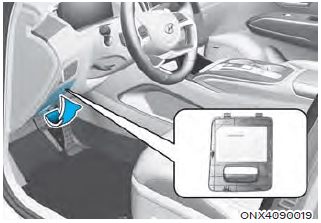
Instrument Panel Fuse Replacement

- Turn the vehicle off.
- Turn all other switches off.
- Open the fuse panel cover.
- Refer to the label on the inside of the fuse panel cover to locate the suspected fuse location.

- Pull the suspected fuse straight out. Use the removal tool (1) provided in the engine compartment fuse panel.
- Check the removed fuse; replace it if it is blown. Spare fuses are provided in the instrument panel fuse panels (or in the engine compartment fuse panel).
- Push in a new fuse of the same rating, and make sure it fits tightly in the clips. If it fits loosely, consult an authorized HYUNDAI dealer.
In an emergency, if you do not have a spare fuse, use a fuse of the same rating from a circuit you may not need for operating the vehicle, such as the cigarette lighter fuse. If the headlights or other electrical components do not work and the fuses are undamaged, check the fuse panel in the engine compartment. If a fuse is blown, it must be replaced with the same rating.
Engine Compartment Panel Fuse Replacement
Blade fuse / Cartridge fuse

- Turn the vehicle off.
- Turn all other switches off.
- Remove the fuse panel cover by pressing the tap and pulling up.
- Check the removed fuse; replace it if it is blown. To remove or insert the fuse, use the removal tool in the engine compartment fuse panel.
- Push in a new fuse of the same rating, and make sure it fits tightly in the clips. If it fits loosely, consult an authorized HYUNDAI dealer.
NOTICE
After checking the fuse panel in the engine compartment, securely install the fuse panel cover. You may hear a clicking sound if the cover is securely latched. If it is not securely latched, electrical failure may occur from water contact.
Multi fuse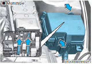
If the multi fuse or midi fuse is blown, consult an authorized HYUNDAI dealer
Fuse/Relay Panel Description
Instrument panel fuse panel
Inside the fuse/relay box cover, you can find the fuse/relay label describing fuse/ relay names and ratings.
Information
Not all fuse panel descriptions in this manual may be applicable to your vehicle; the information is accurate at the time of printing. When you inspect the fuse box on your vehicle, refer to the fuse box label.
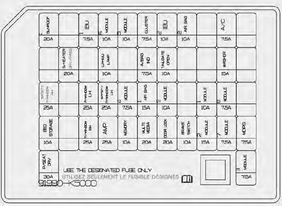
Instrument panel fuse panel
| Fuse Name | Fuse Rating | Circuit Protected |
| SUNROOF1 | 20A | Sunroof Glass Motor Controller |
| IBU1 | 7.5A | IBU |
|
MODULE6 |
10A |
Console Switch, Upper Console Switch, A/T Shift Lever Indicator |
|
MODULE5 |
10A |
AMP, A/C Control Switch, A/C Control Module, Electro Chromic Mirror,
Data Link Connector, Audio, A/V & Navigation Head Unit, Front Wireless Charger, Front Air Ventilation Seat Control Module, Front Seat Warmer Control Module |
| CLUSTER | 7.5A | Instrument Cluster |
| IBU2 | 10A | IBU, Ignition Switch, IAU, BLE Unit |
| AIR BAG2 | 10A | SRS Control Module |
| A/C | 7.5A | A/C Control Module, A/C Control Switch, E/R Junction Block (PTC Heater Relay) |
| S/HEATER DRV/PASS | 20A | Front Air Ventilation Seat Control Module, Front Seat Warmer Control Module |
| CARGO LP | 10A | High-mounted Stop Lamp, Side Mounted Bed Lamp LH/ RH |
| A/BAG IND | 7.5A | Instrument Cluster, Overhead Console Lamp |
| TAILGATE OPEN | 10A | Tailgate Relay |
| WASHER | 15A | Multifunction Switch |
| SAFETY P/WINDOW RH | 25A | Passenger Safety Power Window Module |
| P/WINDOW LH | 25A | Power Window Main Switch |
| SAFETY P/WINDOW LH | 25A | Driver Safety Power Window Module |
| Fuse Name | Fuse Rating | Circuit Protected |
|
MODULE4 |
7.5A | Front View Camera, Crash Pad Switch, WD ECM, ADAS Parking ECU |
|
AIR BAG1 |
15A | SRS Control Module, Passenger Occupant Detection Sensor |
|
MODULE9 |
10A |
Hazard Switch, Key Solenoid, Crash Pad Switch, Data Link Connector, Rain Sensor, Driver/Passenger Smart Key Outside Handle, Sport Mode Switch, E/R Junction Block (E-CVVT Relay) |
|
MODULE1 |
10A | IBU, IAU, Audio, A/V & Navigation Head Unit, Keyboard, Intergrated Parking Assist Unit |
|
MODULE8 |
7.5A |
Front Air Ventilation Seat Control Module, AC Inverter Module, Front Seat Warmer Control Module, AC Inverter Outlet |
| BED STORAGE | 10A | Bed Storage Relay |
| P/WINDOW RH |
25A |
Power Window Main Switch, Passenger Power Window Switch |
| AMP | 25A | AMP |
|
MEMORY |
10A |
Instrument Cluster, Driver/Passenger Door Mood Lamp, Mood Lamp Unit, Crash Pad Mood Lamp, A/C Control Module, A/C Control Switch |
| MULTIMEDIA | 25A | Audio, A/V & Navigation Head Unit |
| DOOR LOCK | 20A | Center Door Lock Relay, Center Door Unlock Relay, Two Turn Unlock Relay |
| BRAKE SWITCH | 10A | Stop Lamp Switch, IBU |
| MODULE2 | 15A | Front USB Charger, Rear USB Charger |
| MODULE7 | 7.5A | IBU, IAU |
| MDPS | 7.5A | MDPS Unit |
| P/SEAT DRV | 30A | Driver Power Seat Switch, Driver Power Seat Module |
| MODULE3 | 7.5A | Stop Lamp Switch, IAU, Sport Mode Switch (DCT) |
Engine compartment fuse panel (Engine room junction block)
Inside the fuse/relay box cover, you can find the fuse/relay label describing fuse/ relay names and ratings.

Information
Not all fuse panel descriptions in this manual may be applicable to your vehicle; the information is accurate at the time of printing. When you inspect the fuse panel in your vehicle, refer to the fuse panel label.
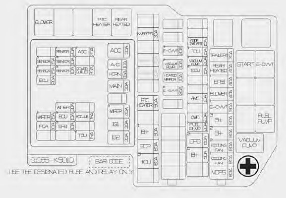
Engine compartment fuse panel
| Type | Fuse Name | Fuse Rating | Circuit Protected |
|
MULTI FUSE |
MDPS | 80A | MDPS Unit |
| COOLING FAN1 | 80A | [G4KP] Cooling Fan Controller | |
| COOLING FAN2 | 60A | [G4KN] Cooling Fan Controller | |
| B+2 | 60A | ICU Junction Block (IPS7, IPS8, IPS9, IPS10, IPS11, IPS12) | |
|
B+3 |
60A |
ICU Junction Block (Fuse – P/SEAT DRV, SAFETY P/ WINDOW RH, S/HEATER DRV/PASS, SUNROOF1, BED
STORAGE, Power Window Main Relay) |
|
| E-CVVT1 | 50A | E/R Junction Block (E-CVVT Relay) | |
| BLOWER | 40A | E/R Junction Block (Blower Relay) | |
| EPB1 | 40A | ESC Module | |
| REAR HEATED | 40A | E/R Junction Block (Rear Heated Relay) | |
| TRAILER 1 | 30A | [G4KP] Trailer Connector | |
|
FUSE |
B+4 |
40A |
ICU Junction Block (Fuse – DOOR LOCK, SAFETY P/ WINDOW LH, TAILGATE OPEN, AMP, IBU2, AIR BAG2, CARGO LP, BRAKE SWITCH, MODULE9, Long Term
Load Latch Relay) |
| EPB2 | 60A | ESC Module | |
| FUEL PUMP | 20A | E/R Junction Block (Fuel Pump Relay) | |
| 4WD | 20A | AWD ECM | |
| TRAILER 2 | 30A | [G4KN] Trailer Controller | |
| AMS | 10A | Battery Sensor | |
| TRAILER 3 | 30A | [G4KN] Trailer Connector | |
| ECU2 | 15A | PCM/ECM | |
| VACUUM PUMP1 | 20A | [G4KP] E/R Junction Block (Vacuum Pump Relay) | |
| TCU1 | 15A | [G4KN] PCM | |
| ROOF LIGHT FRT | 15A | Accessory Light Switch | |
| E-CVVT2 | 20A | [G4KP] ECM | |
| HEATED MIRROR | 10A | E/R Junction Block (Rear Heated Relay), Driver/ Passenger Power Outside Mirror | |
| VACUUM PUMP2 | 10A | [G4KP] ESC Module | |
| TCU3 | 60A | [G4KP] TCM | |
| EOP | 60A | [G4KP] Electronic Oil Pump | |
| B+1 | 50A | ICU Junction Block (IPS1, IPS3, IPS4, IPS5, IPS6,) | |
| PTC HEATER | 50A | E/R Junction Block (PTC Heater Relay) | |
| INVERTER | 30A | AC Inverter Module |
| Type | Fuse Name | Fuse Rating | Circuit Protected |
|
FUSE |
ACC1 | 50A | ACC Relay |
| MAIN | 60A | Main Relay | |
| WIPER3 | 40A | Front Wiper1 On Relay | |
| IG1 | 60A | IG1 Relay | |
| IG2 | 60A | IG2 Relay, E/R Junction Block (Start Relay) | |
| SENSOR1 | 20A | Ignition Coil #1/#2/#3/#4 | |
| ACC2 | 20A | ICU Junction Block (Fuse – MODULE1, MODULE2) | |
| SENSOR5 | 15A | Injector #1/#2/#3/#4 (MPI) | |
| SENSOR4 | 10A | E/R Junction Block (Fuel Pump Relay) | |
| SENSOR2 | 15A | Oxygen Sensor (Up), Oxygen Sensor (Down) | |
|
SENSOR3 |
10A |
A/C Comp Relay, Oil Control Valve (Exhaust), Valiable Oil Pump Solenoid, Purge Control Solenoid Valve, Cooling Fan Controller, Canister Close Valve [G4KN] Variable Intake Solenoid Valve / [G4KP] RCV Control Solenoid Valve | |
| POWER OUTLET | 20A | Front Power Outlet | |
| A/C | 10A | A/C Comp Relay | |
| HORN | 10A | Horn Relay | |
| ECU1 | 20A | PCM/ECM | |
| WIPER1 | 30A | Front Wiper2 (Low) Relay, Front Wiper Motor | |
| WIPER2 | 7.5A | IBU | |
| ECU3 | 10A | PCM/ECM | |
| MODULE | 7.5A | [G4KP] E/R Junction Block (Vacuum Pump Relay) | |
| FCA | 10A | Front Radar | |
| EPB3 | 10A | ESC Module | |
| TCU2 | 15A | [G4KP] TCM |
FAQs
Fuses protect electrical components from overloading, and if a particular system malfunctions, it’s crucial to check and replace the fuse if necessary.
The fuse box is typically located in the engine compartment or the interior of the vehicle.
Yes, a blown fuse can impact various electrical systems, such as lights, radio, or power windows. The fuse diagram helps identify the specific fuse for each component.
Look for a melted or broken wire inside the transparent window on top of the fuse. If the wire is damaged, the fuse is likely blown.
Most fuses can be changed with a fuse puller or a pair of needle-nose pliers. Ensure you have the correct replacement fuse as well.
The correct amperage is usually printed on the top of the fuse. It’s crucial to replace it with a fuse of the same amperage to avoid damaging the electrical system.
No, it’s essential to use the correct amperage fuse. Using a higher amperage fuse can lead to electrical system damage or even pose a fire hazard.
Some fuse boxes come with spare fuses.
Regularly inspect your fuses during routine maintenance checks. Change any blown fuses immediately to ensure optimal performance.
The fuse diagram illustrates the location and amperage of each fuse, helping you identify which one corresponds to the malfunctioning system.
Yes, the fuse box may be divided into sections, each corresponding to a specific system (e.g., lights, radio, power windows).
Yes, extreme temperatures can impact fuse performance. Store spare fuses in a cool, dry place to ensure their reliability.
If a fuse consistently blows, there may be an underlying issue. Consult your dealer or a mechanic to identify and fix the root cause.
While color coding can help identify fuses, always prioritize using the correct amperage fuse, regardless of its color.
Useful Link
View Full PDF: 2024 Hyundai Santa Cruz Owner’s Manual
2024 Hyundai SANTA CRUZ Specs, Price, Features, Mileage and Review