
![]()
Fixing a blown fuse: 2014 Hyundai Elantra Fuse Diagram Guide
Fixing a blown fuse in a 2014 Hyundai Elantra opens up a world of complicated electrical issues and turns solving into an art form. The fuse diagram is like a map; it shows car fans how to find their way through the complicated web of circuits that power all of the car’s features. Finding and fixing a blown fuse is a lot like solving a problem in a car; it takes a lot of technical know-how and patience. Each fuse is like a guardian of electrical balance, and it’s very important to understand the diagram in this diagnostic dance. By going into the heart of the fuse box with the help of the diagram, the possibility of getting the car working again turns into a real victory over mechanical problems. In the end, replacing a blown fuse in a 2014 Hyundai Elantra isn’t just a repair job; it’s a trip into the heart of the car’s electrical system, where the skilled user of the diagram becomes the hero who restores smooth car operation.
2023 Hyundai Elantra Specs, Price, Features, Milage (Brochure)
FUSES

A vehicle’s electrical system is protected from electrical overload damage by fuses. This vehicle has 2 (or 3) fuse panels, one located in the driver’s side panel bolster, the other in the engine compartment near the battery. If any of your vehicle’s lights, accessories, or controls do not work, check the appropriate circuit fuse. If a fuse has blown, the element inside the fuse will be melted or broken. If the electrical system does not work, first check the driver’s side fuse panel. Before replacing a blown fuse, disconnect the negative battery cable. Always replace a blown fuse with one of the same rating. If the replacement fuse blows, this indicates an electrical problem. Avoid using the system involved and immediately consult an authorized HYUNDAI dealer.
NOTICE
Three kinds of fuses are used: blade type for lower amperage rating, cartridge type, and fusible link for higher amperage ratings.
WARNING
NEVER replace a fuse with anything but another fuse of the same rating.
- A higher capacity fuse could cause damage and possibly a fire.
- Do not install a wire or aluminium foil instead of the proper fuse – even as a temporary repair. It may cause extensive wiring damage and possibly a fire.
CAUTION
Do not use a screwdriver or any other metal object to remove fuses because it may cause a short circuit and damage the system.
Instrument panel fuse replacement
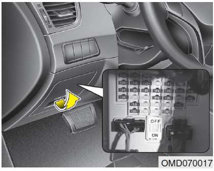
- Turn the engine off.
- Turn all other switches OFF.
- Open the fuse panel cover.

- Refer to the label on the inside of the fuse panel cover to locate the suspected fuse location
- Pull the suspected fuse straight out. Use the removal tool provided in the engine compartment fuses panel.
- Remove and check the suspected fuse; replace it if it is blown. Spare fuses are provided in the instrument panel fuse panels (or in the engine compartment fuse panel).
- Push in a new fuse of the same rating, and make sure it fits tightly in the clips. If it fits loosely, consult an authorized HYUNDAI dealer.
In an emergency, if you do not have a spare fuse, use a fuse of the same rating from a circuit you may not need for operating the vehicle, such as the cigarette lighter fuse. If the headlights or other electrical components do not work and the fuses are OK, check the fuse panel in the engine compartment. If a fuse is blown, it must be replaced.
Memory fuse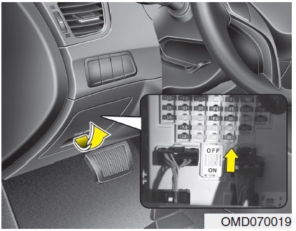 Always, put the fuse switch at the ON position. If you move the switch to the OFF position, some items such as the audio and digital clock must be reset and the remote key (or smart key) may not work properly.
CAUTION
Always place the fuse switch in the ON position while driving the vehicle.
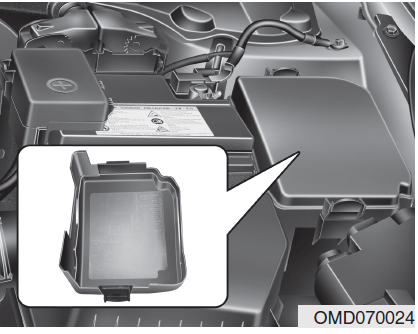
Engine compartment panel fuse replacement
- Turn the engine off.
- Turn all other switches OFF.
- Remove the fuse panel cover by pressing the tap and pulling up.
- Remove and check the suspected fuse; replace it if it is blown. To remove or insert the fuse, use the fuse puller in the engine compartment fuse panel.
- Push in a new fuse of the same rating, and make sure it fits tightly in the clips. If it fits loosely, consult an authorized HYUNDAI dealer.
Main fuse

If the main fuse is blown, it must be removed as follows:
- Turn off the engine.
- Disconnect the negative battery cable.
- Remove the fuse panel cover by pressing the tap and pulling it up.
- Remove the nuts shown in the picture above.
- Replace the fuse with a new one of the same rating.
- Reinstall in the reverse order of removal.
✽ NOTICE
If the main fuse is blown, consult an authorized HYUNDAI dealer.
Multi fuse
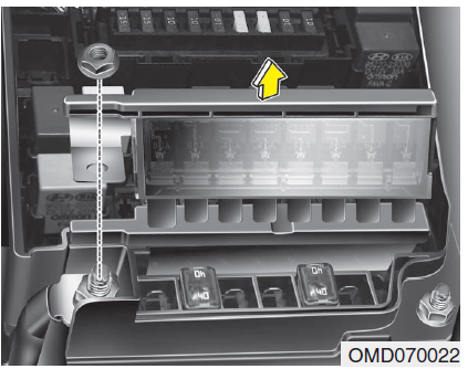
If the multi fuse is blown, it must be removed as follows:
- Turn off the engine.
- Disconnect the negative battery cable.
- Remove the fuse panel cover by pressing the tap and pulling up.
- Remove the bolts shown in the picture above.
- Replace the fuse with a new one of the same rating.
- Reinstall in the reverse order of removal.
✽ NOTICE
If the multi fuse is blown, consult an authorized HYUNDAI dealer.
Fuse/relay panel description
Instrument panel fuse panel

Inside the fuse/relay panel covers, you can find the fuse/relay label describing fuse/relay name and capacity.
✽ NOTICE
Not all fuse panel descriptions in this manual may be applicable to your vehicle. It is accurate at the time of printing. When you inspect the fuse panel in your vehicle, refer to the fuse panel label.

Instrument panel (Driver’s side fuse panel)
| Fuse Name | Fuse rating | Protected Component |
| START | 7.5A | W/O Smart Key : ICM Relay Box(Burglar Alarm Relay), With Smart Key : A/T – Transaxle Range Switch, M/T – ECM, E/R Fuse & Relay Box(Start 1 Relay), Smart Key Control Module |
| A/BAG | 15A | SRS Control Module, Passenger Weight Classification Sensor |
| A/BAG IND | 7.5A | Instrument Cluster |
| CLUSTER | 7.5A | ISG LDC (Audio), Cluster (ISG) |
| C/LIGHTER | 15A | Cigarette Lighter |
| BCM | 7.5A | Smart Key Control Module, BCM |
| A/CON SWITCH | 7.5A | A/C Control Module |
| MODULE 2 | 7.5A | Electro Chromic Mirror, ESC Off Switch |
| MDPS | 10A | EPS Control Module |
| MODULE 4 | 7.5A | Rear Parking Assist Sensor LH/RH (IN/OUT), A/C Control Module(Auto A/C), ATM Lever Indicator |
| IG1 | 20A | E/R Fuse & Relay Box(Fuse – TCU 1, B/UP LP, ECU 3, ABS 3) |
| PDM 3 | 7.5A | Smart Key Control Module |
| POWER OUTLET FRT | 20A | Power Outlet |
| MODULE 6 | 10A | AMP, Power Outside Mirror Switch, Audio, A/V & Navigation Head Unit, Digital Clock |
| Fuse Name | Fuse rating | Protected Component |
| HTD MIRR | 10A | Driver/Passenger Power Outside Mirror, A/C Control Module |
| MODULE 3 | 7.5A | Audio, Tire Pressure Monitoring Module, Digital Clock, BCM, Instrument Cluster, Driver/Passenger Seat Warmer Module |
| BRAKE SWITCH | 10A | – |
| SPARE | 15A | – |
| SUNROOF | 15A | Sunroof |
| SPARE | 15A | – |
| SPARE | 15A | – |
| BLOWER | 10A | Manual A/C – A/C Control Module, ECM/PCM, Blower Resistor |
| INTERIOR LAMP | 10A | Luggage Lamp, Vanity Lamp LH/RH, Room Lamp, Overhead Console Lamp, Ignition Key Ill. & Door Warning Switch(W/O Smart Key) |
| TRUNK | 10A | Trunk Relay |
| MODULE 1 | 7.5A | Sport Mode Switch(A/T), Key Solenoid(W/O Smart Key) |
| SPARE | 15A | – |
| S/HEATER RR | 15A | Rear Seat Warmer Switch LH/RH |
| MODULE 7 | 7.5A | Smart Key Control Module, BCM |
| MULTIMEDIA | 15A | Audio, A/V & Navigation Head Unit |
| Fuse Name | Fuse rating | Protected Component |
| P/WDW RH | 25A | P/WDW RH Relay |
| PDM 2 | 7.5A | Smart Key Control Module, Start Stop Button Switch |
| SPARE | 10A | – |
| WIPER FRT | 25A | ICM Relay Box(Rain Sensor Relay), Multifunction Switch, Wiper Motor, E/R Fuse & Relay Box(Wiper Relay) |
| MODULE 5 | 7.5A | Cluster Ionizer(Auto A/C), Rain Sensor, Sunroof |
| SPARE | 7.5A | – |
| AMP | 25A | AMP |
| PDM 1 | 25A | Smart Key Control Module |
| SPARE | 20A | – |
| A/CON | 7.5A | A/C Control Module, E/R Fuse & Relay Box(Blower Relay) |
|
MEMORY |
10A |
Tire Pressure Monitoring Module, BCM, Auto Light & Photo Sensor, Instrument Cluster, Data Link Connector, Smart Junction Box Upgrade Connector, Electro Chromic Mirror, A/C Control Module, Digital Clock |
| P/WDW LH | 25A | P/WDW LH Relay, Driver Safety Power Window Module |
| DR LOCK | 20A | Door Lock Relay, Door Unlock Relay, ICM Relay Box(Two Turn Relay) |
| P/SEAT DRV | 30A | Driver Seat Manual Switch |
Engine compartment fuse panel
Inside the fuse/relay panel covers, you can find the fuse/relay label describing fuse/relay name and capacity.
✽ NOTICE
Not all fuse panel descriptions in this manual may be applicable to your vehicle. It is accurate at the time of printing. When you inspect the fuse panel in your vehicle, refer to the fuse panel label.

Engine compartment main fuse panel
| Description | Fuse rating | Protected components | |
|
MULTI FUSE |
MDPS | 80A | EPS Control Module |
| B+1 | 60A | Smart Junction Box(ARISU 1 (4CH), IPS 1, FUSE – P/WDW LH, P/WDW RH, TRUNK, AMP 1) | |
| C/FAN | 40A | C/FAN Lo Relay, C/FAN Hi Relay | |
| ABS 1 | 40A | ESC Module, Multipurpose Check Connector | |
| RR HTD | 40A | RR HTD Relay | |
| BLOWER | 40A | Blower Relay | |
| SPARE | 40A | – | |
| B+2 | 60A | Smart Junction Box(Turn Signal Lamp Sound Relay, ARISU 2 (4CH), IPS (1CH), IPS (2CH), FUSE – P/SEAT DRV, SUNROOF) | |
|
FUSE |
B/UP LAMP | 10A | Electro Chromic Mirror, A/V & Navigation Head Unit, Rear Combination Lamp (In) LH/RH, M/T – Back-Up Lamp Switch, BCM, Instrument Cluster |
| TCU 1 | 15A | M/T – Vehicle Speed Sensor, A/T – Transaxle Range Switch | |
| ABS 3 | 10A | ESC Module, Multipurpose Check Connector | |
| ECU 3 | 10A | Stop Lamp Switch, M/T – ECM, A/T – PCM | |
| WIPER | 10A | Rain Sensor, M/T – ECM, A/T – PCM | |
| B+3 | 50A | Smart Junction Box (Leak Current Autocut Device, FUSE – MODULE 1, PDM 1, PDM 2, DR LOCK) | |
| EMS | 40A | EMS Box(Engine Control Relay, FUSE – ECU 4, A/CON, F/PUMP) | |
| Description | Fuse rating | Protected components | |
|
FUSE |
ISG INVERTER | 50A | Oil Pump Inverter |
| STOP LP | 15A | Stop Lamp Switch, Smart Key Control Module | |
| S/HEATER FRT | 20A | Driver/Passenger Seat Warmer Module | |
| HORN | 15A | Horn Relay | |
| IG 2 | 40A | W/O Smart Key : Ignition Switch, Start 1 Relay, With Smart Key : PDM 4 (IG2) Relay, Start 1 Relay | |
| ABS 2 | 30A | ESC Module, Multipurpose Check Connector | |
| IG 1 | 40A | W/O Smart Key : Ignition Switch, With Smart Key : PDM 3 (IG1) Relay, PDM 2 (ACC) Relay | |
| F/PUMP | 15A | F/PUMP Relay | |
| ECU 4 | 15A | PCM (A/T), ECM (M/T) | |
| A/CON | 10A | A/C COMP Relay | |
| INJECTOR | 10A | Injector #1 / #2 / #3 / #4, A/C COMP Relay, F/PUMP Relay | |
| ECU 2 | 10A | PCM (A/T), ECM (M/T) | |
| IGN COIL 1 | 20A | Ignition Coil #1 / #2 / #3 / #4, Condenser | |
| ECU 1 | 20A | – | |
| SENSOR 2 | 10A | Immobilizer Module, Camshaft Position Sensor #1 / #2 | |
| Description | Fuse rating | Protected components | |
|
FUSE |
SENSOR 1 | 10A | Oxygen Sensor (UP/DOWN), Canister Close Valve, Variable Intake Solenoid Valve, Oil Control Valve #1 / #2, Purge Control Solenoid Valve, C/FAN LO Relay, C/FAN HI Relay |
| SPARE | 10A | – | |
| SPARE | 15A | – | |
| SPARE | 20A | – | |
FAQs
A blown fuse occurs when it breaks due to overloads or faults, disrupting the electrical flow to a specific component. It can affect various functions in your Hyundai Elantra.
The fuse box is typically located in accessible areas such as the engine compartment or interior.
Look for a visibly broken wire or a discolored appearance. Use a fuse diagram, available in the fuse box cover, to identify the specific fuse related to the malfunctioning component.
Yes, a blown fuse can affect various electrical components. Identifying and replacing the faulty fuse is crucial to restoring functionality.
Yes, fixing a blown fuse is a relatively simple process that many car owners can do themselves.
Regularly inspect fuses during routine maintenance or when you experience electrical issues to ensure optimal vehicle performance.
A fuse puller or a pair of pliers and replacement fuses of the correct amperage are usually sufficient.
No, it’s crucial to replace a blown fuse with one of the same amperage to prevent damage to the electrical system.
Refer to the fuse diagram to identify the specific fuse related to the malfunctioning component. Replace the blown fuse with a new one of the same amperage.
It depends on the function affected by the blown fuse. Certain components may be crucial for safe driving, so it’s advisable to address the issue promptly.
Ensure the vehicle is turned off before working with the fuse box to avoid electrical shocks. If uncertain, seek professional assistance.
While occasional blown fuses are normal, recurring issues may indicate an underlying electrical problem that requires professional diagnosis.
Overloading electrical circuits, faulty components, or wiring issues can contribute to blown fuses. Addressing these root causes can prevent recurrent issues.
Useful Link
View Full PDF: 2014 Hyundai Elantra Owner’s Manual
2023 Hyundai Elantra Specs, Price, Features, Milage (Brochure)