
Alliance RV Valor 2021 User Manual
The Alliance RV Valor 2021 is a great example of how luxury and new ideas can come together in a mobile vehicle. With its long list of great features and careful attention to every detail, the Valor 2021 shows that Alliance RV is dedicated to giving travelers the most comfort and ease possible. This top-of-the-line model has a variety of floor plans to fit different tastes and make sure that every trip is perfect. With its roomy and well-thought-out cabin, the Valor 2021 is a welcoming home on wheels that can meet a wide range of travel needs. Its solid build, high-quality materials, and state-of-the-art technology make it a real standout among RVs, promising both durability and usefulness. Whether you’ve been traveling for a long time or you’re new to the RV lifestyle, the Alliance RV Valor 2021 promises to change the way you travel. It has the perfect mix of style, comfort, and functionality for those who want the best on their trips.
alliance RV Valor 2021 Owners Information Bag User Manual
2021 alliance RV Valor Owners Information Bag User Guide
Owners Information Bag
You will find the manuals and registration cards for individual components in your Alliance RV Fifth Wheel Owner’s Information Bag.
It is important that you take time to register and activate each component warranty according to the information and timelines provided. Doing so will help any potential delays in the event your RV requires warranty service. Failure to register these warranties will not dismiss warranty coverage, although it could cause delays. Please contact Alliance Customer Service with any questions.
Alliance RV Customer Service Contact Information:
Phone: (574) 226‐0140
Email: service@alliancerv.com
VEHICLE IDENTIFICATION NUMBER (VIN)
Alliance RV vehicles all have a unique 17‐digit VIN. You will find your VIN listed on the Federal Certification label located toward the front of the RV on the off‐door side. The following VIN decoder identifies each digit location and its function.
| DIGIT LOCATION | FUNCTION | KEY |
| 1st, 2nd and 3rd | WMI (SAE Assigned) | 7M5 |
| Trailer Type | F = Fifth Week
X = TBD |
|
| X 4th = TBD | ||
| 5th | Model Designator | P = Paradigm
X = TBD |
| X = TBD | ||
| X = TBD | ||
| 6th and 7th | Length of RV | Length of RV (2 digits regardless of length) |
| 8th | Number of Axles | 1 = 1 Axle
2 = 2 Axles |
|||
| 9th | Check Digit | Calculated | |||
| 10th | Model Year | M = 2021
N = 2022 |
T = 2026
V = 2027 |
1 = 2031
2 = 2032 |
6 = 2036
7 = 2037 |
| P = 2023 | W = 2028 | 3 = 2033 | 8 = 2038 | ||
| R = 2024 | X = 2029 | 4 = 2034 | 9 = 2039 | ||
| S = 2025 | Y = 2030 | 5 = 2035 | |||
| 11th | Plant Location | A = Plant 1
B = Plant 2 |
|||
| C = Plant 3 | |||||
| D = Plant 4 | |||||
REPORTING SAFETY DEFECTS
In the United States:
If you believe that your recreational vehicle has a defect that could cause a crash or cause injury or death, you should immediately inform the National Highway Traffic Safety Administration (NHTSA), and Alliance RV. If the National Highway Traffic Safety Administration (NHTSA) receives similar complaints, they may open an investigation. If they determine that a safety defect exists in other vehicles, a recall and remedy campaign may be ordered. NHTSA does not become involved in individual cases between you, your dealer or Alliance RV.
To Contact NHTSA:
Website: www.safecar.gov
Address: NHTSA Headquarters Attn: Administrator 1200 New Jersey Avenue, SE Washington DC 20590 Toll-Free Vehicle Safety Hotline: 888.327.4236 TTY: 800.424.9153
For additional information, please refer to the NHTSA website at www.safecar.gov.
In Canada:
If you believe that your recreational vehicle has a defect that could cause a crash or cause injury or death, you should immediately inform Transportation Canada’s Defect Investigations and Recalls Division, and Alliance RV.
To Contact Transportation Canada
Website: www.tc.gc.ca
Address: Transport Canada Defect Investigations & Recalls Division 330 Sparks Street Ottawa ON K1A 0N5 Canada Toll-Free in Canada: 800.333.0510.
Read all Instructions for Owners Information Bag User Manual
alliance RV Valor 2021 OBTAINING SERVICE User Manual
alliance RV Valor 2021 OBTAINING SERVICE User Manual
OBTAINING SERVICE
For a defect to be covered under either limited warranty, the repair or replacement must occur at an independent authorized Alliance RV dealer, or Alliance RV designated repair shop or Alliance RV facilities. Alliance RV will remedy defects in materials and workmanship covered under the Limited Base Warranty or Limited Structural Warranty, under normal use and service, caused by Alliance RV in the recreational vehicle itself only.
To obtain warranty service the original retail purchaser must do the following:
- Within twenty (20) days of discovery of any defect to be covered by this warranty, notify an independent, authorized Alliance RV dealer or Alliance RV. Warranty services can only be obtained through Alliance RV authorized dealers and service representatives.
- Following notification, the recreational vehicle must be taken to an independent, authorized Alliance RV dealer, or if authorized by Alliance RV, a designated repair shop. Either that dealer or repair shop, or Alliance RV will undertake appropriate corrective repair actions in instances where the defect is covered by this warranty. All costs incurred in transporting this recreational vehicle for warranty service shall be borne by the purchaser unless otherwise approved in advance by Alliance RV.
If assistance is needed, you may contact Alliance RV at:
Email: service@alliancerv.com
Phone:(574) 226‐0140
Mail: 301 Benchmark Drive, Elkhart, IN 46516 (Attn: Customer Service)
REPAIR REMEDY; EXCLUSIVE REMEDY
Alliance RV’s obligation is to address, within industry standards, any covered substantial defect discovered and reported within the warranty period provided: (a) you notify an authorized dealer within 20 days of your discovery of the substantial defect: AND (b) you deliver the recreational vehicle to an authorized dealership or Alliance RV at your cost and expense. If this primary remedy fails to successfully cure any substantial defect after a reasonable number of repair attempts, your sole and exclusive remedy shall be to have Alliance RV pay an independent service shop to perform repairs to the defect. If the defect is still incapable of being repaired, Alliance RV may, at its option, provide you the diminished value damages (the difference in the purchase price and actual value of your recreational vehicle on the date of purchase). You must exhaust the primary repair remedy and this backup remedy, and both these remedies must fail of their essential purpose before initiating any action against Alliance RV.
WARRANTY EXCLUSIONS
The Limited Base and Limited Structural Warranties noted above will not cover and will not apply to:
- Routine maintenance and adjustments;
- Any deterioration due to normal wear and tear;
- Defects in labor, materials, components or parts not manufactured or performed by Alliance RV;
- Modifications or alterations to the original design after the recreational vehicle leaves possession of Alliance RV;
- Damage caused by unauthorized attachments, modifications or alterations;
- Equipment or accessories installed by any party other than Alliance RV;
- Materials, components, appliances, electronics or parts are warranted separately by the respective component manufacturer;
- Recreational vehicles used for purposes other than recreational travel and camping (By way of example only business, rental commercial or disaster relief purposes);
- Any recreational vehicle purchased in the United States with the specific intent to import vehicle to Canada;
- Any recreational vehicle registered or primarily used outside the United States or Canada;
- Any water leaks or related significant damages that are a result of your failure to properly maintain the exterior seals as required in the Owner’s Manual;
- Repairs or replacements made necessary as a result of your failure to follow ordinary maintenance procedures as recommended by Alliance or the manufacturer or dealer of the recreational vehicle;
- Rust or corrosion due to the environment;
- Damage caused by misuse, abuse, neglect, theft, or vandalism;
- Damage caused by improper stowing of equipment, overloading or improper load balancing;
- Damage caused by unprotected electrical hookups or power surges;
- Damage caused by extreme weather conditions such as extreme cold or heat, winds, rain, lightning, hail, ice, and flooding;
- Damage caused by unauthorized repair or failure to follow instructions supplied with the recreational vehicle;
- Damage caused by the tow vehicle by the owner, owner’s operation or use of the tow vehicle, improper selection or installation of towing hitch on the tow vehicle, or damage to the owner’s tow vehicle;
- Damage caused by road conditions, applications of salt or de‐icing chemicals, gravel, sand, potholes, etc.
- Fading, yellowing, or aging of exterior materials and components due to exposure of UV or sunlight, or weather;
- Damage caused in transit to or from a dealer, or to or from the consumer, or by the consumer or another;
- Recreational vehicles were not originally purchased through an authorized Alliance RV dealer.
- Fading, yellowing, or aging of exterior materials and components due to exposure of UV or sunlight, or weather;
- Damage caused in transit to or from a dealer, or to or from the consumer, or by the consumer or another;
- Recreational vehicles not originally purchased through an authorized Alliance RV dealer
Read all Instructions for OBTAINING SERVICE User Manual
alliance RV Valor 2021 Warranty Exclusions User Manual
alliance RV Valor 2021 Warranty Exclusions User Manual
WARRANTY EXCLUSIONS
EVENTS DISCHARGING ALLIANCE RV FROM OBLIGATION UNDER WARRANTY
Certain things completely discharge Alliance RV from any obligation under these warranties. By way of example, the following shall discharge Alliance RV from any express or implied warranty obligation to repair or replace any defect that results from: misuse or negligent use, abuse, or accident, neglect, unauthorized alteration, failure to provide reasonable and necessary maintenance including reasonable periodic inspections of the recreational vehicle, use of the recreational vehicle for rental, business or commercial use or any other use other than to use the recreational vehicle only for recreational and personal use.
WARRANTY REGISTRATIONS
The selling dealer will assist you in completing and submitting the Alliance RV product warranty registration form. That form must be returned to Alliance RV within ten (10) days of your taking delivery of the recreational vehicle. Failure to file this warranty registration with Alliance RV will not affect your rights under the Limited Base or Limited Structural warranties as long as you can present proof of purchase, but it can cause delays in obtaining the benefits of these Limited Warranties and may inhibit any servicing facility’s ability to provide proper repairs and/or part replacement.
As stated above, some components, accessories or equipment are not covered by these Limited Warranties. By way of example, the following have coverage that may be provided by the component manufacturer: tires, batteries, generators, and some appliances & electronics and entertainment equipment. These component manufacturer warranties are separate from this Limited Base Warranty, and in some cases may be longer and/or have specific coverage provisions and requirements. In order to activate these warranties, you may have to complete registration forms, post cards or some other form of notification to the component manufacturer within a specific time period. These forms and documents will be located with the Owner’s Materials packet provided with your new vehicle. You must complete and submit them to the respective manufacturer as quickly as possible, and within the time periods required by those warranties.
CARE AND MAINTENANCE
The owner of the recreational vehicle is responsible to perform proper care and maintenance of the recreational vehicle as outlined in the Alliance RV Owner’s Manual and the owner’s manuals of the chassis and other component part manufacturers. Failure to maintain the RV as noted in those manuals voids these warranties, and any damage to the RV as a result of your failure to perform such care, is not covered by the warranties set forth above.
LEGAL REMEDIES ANY ACTION TO ENFORCE ANY PORTION OF THIS LIMITED BASE OR STRUCTURAL WARRANTIES, OR ANY IMPLIED WARRANTY, MUST BE COMMENCED WITHIN NINETY (90) DAYS AFTER THE EXPIRATION OF THE APPLICABLE WARRANTY COVERAGE PERIOD. ANY PERFORMANCE OF REPAIRS WILL NOT SUSPEND THIS LIMITATION PERIOD FROM EXPIRING UNLESS STATE LAW PROVIDES OTHERWISE. ANY PERFORMANCE OF REPAIRS AFTER THE APPLICABLE WARRANTY COVERAGE PERIOD HAS EXPIRED, OR PERFORMANCE OF REPAIRS REGARDING ANYTHING EXCLUDED FROM COVERAGE UNDER THIS LIMITED WARRANTY SHALL BE CONSIDERED “GOODWILL” REPAIRS, AND THEY WILL NOT CHANGE THE EXPRESS TERMS OF THIS LIMITED WARRANTY OR EXTEND THE WARRANTY COVERAGE PERIOD.
EXCLUSIVE JURISDICTION FOR DECIDING LEGAL DISPUTES RELATING TO ALLEGED BREACH OF WARRANTY OR REPRESENTATIONS OF ANY NATURE MUST BE FILED IN THE COURTS WITHIN THE STATE OF MANUFACTURE. THE ABOVE LIMITED WARRANTIES WILL BE INTERPRETED AND CONSTRUED IN ACCORDANCE WITH THE LAWS OF THE STATE OF INDIANA, WITHOUT GIVING EFFECT TO ANY CHOICE OR CONFLICT OF LAW PROVISION OR RULE (WHETHER OF THE STATE OF INDIANA OR ANY OTHER JURISDICTION) THAT WOULD CAUSE THE APPLICATION OF THE LAWS OF ANY JURISDICTION OTHER THAN THOSE OF THE STATE OF INDIANA.
ANY AND ALL CLAIMS, CONTROVERSIES, AND CAUSES OF ACTION ARISING OUT OF OR RELATING TO THE ABOVE LIMITED WARRANTIES, WHETHER SOUNDING IN CONTRACT, TORT OR STATUTE, WILL BE GOVERNED BY THE LAWS OF THE STATE OF INDIANA, INCLUDING ITS STATUTE OF LIMITATIONS, WITHOUT GIVING EFFECT TO ANY CHOICE OR CONFLICT OF LAW PROVISION OR RULE (WHETHER OF THE STATE OF INDIANA OR ANY OTHER JURISDICTION) THAT WOULD CAUSE THE APPLICATION OF THE LAWS OF ANY JURISDICTION OTHER THAN THOSE OF THE STATE OF INDIANA. THE LIMITED BASE WARRANTY AND LIMITED STRUCTURAL WARRANTY GIVE YOU SPECIFIC LEGAL RIGHTS, AND YOU MAY ALSO HAVE OTHER RIGHTS WHICH VARY FROM STATE TO STATE.
Read all Instructions for Warranty Exclusions User Manual
alliance RV Valor 2021 Safety Precautions User Manual
alliance RV Valor 2021 Safety Precautions User Manual
SAFETY PRECAUTIONS
Throughout this manual, you will find the symbols shown below. This information is provided to help you avoid personal injury or death as well as damage to your RV and other property. Take the time to review all these warnings.
CAUTION
CAUTION indicates a hazardous situation which, if not avoided, could result in minor or moderate injury.
WARNING
indicates a hazardous situation which, if not avoided, could result in death or serious injury.
DANGER
DANGER indicates a hazardous situation which, if not avoided, will result in death or serious injury.
WEIGHT RATINGS, ASSOCIATED LABELS, LOADING AND WEIGHING
Weight Terms
WARNING
PLEASE READ AND UNDERSTAND THE MANY SAFETY LABELS THROUGHOUT YOUR RV, FAILURE TO DO SO COULD RESULT IN PROPERTY DAMAGE, DEATH OR SERIOUS INJURY.
Knowing and understanding the following weight terms are a crucial step to the overall safety of your RV. By becoming familiar with this information, you will be better equipped in making decisions when using your Alliance RV product.
GAWR = Gross Axle Weight Rating and is the maximum weight the recreational vehicle’s axle (s) are rated for.
GVWR = Gross Vehicle Weight Rating and is the maximum operating weight the vehicle is rated for when fully loaded.
UVW = Unloaded Vehicle Weight and is the weight of the manufactured completed RV.
CCC = Cargo Carrying Capacity and is the difference between what the RV weighs when there is nothing in it and what it weights when you have loaded it with your personal belongings, also including but not limited to food, water, propane and any upgrades added (ie. solar power, washer/dryer, additional batteries etc.)
HITCH WEIGHT = The weight of the trailer that is on the hitch of the tow vehicle when attached.
WARNING
NEVER EXCEED ANY OF THE DESIGNATED WEIGHT RATINGS, DOING SO COULD RESULT IN DEATH OR SERIOUS INJURY FACTORY INSTALLED WEIGHT LABELS ARE SPECIFIC TO YOUR RV, NEVER REMOVE OR MODIFY THESE LABELS. IF YOU HAVE A MISSING LABEL, CONTACT YOUR DEALER OR ALLIANCE RV FOR ASSISTANCE.
Federal Certification
This label verifies that your RV is compliant with all Vehicle Safety Standards. You’ll find this label near the front of your RV on the off‐door side near the cabover.
Tire and Loading Information
This label houses information regarding the correct tire pressure for the vehicle and will also tell you the size of the tires and the CCC of the RV. This label is also located near the front of the RV on the off‐door side near the cabover.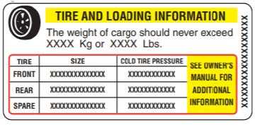
Cargo Capacities & Weighing Your RV
The weight and balance of your RV is crucial to your safety. To ensure that you are within all the established weight limits and ratings, you should have your RV weighed. Always make sure that your RV is loaded evenly from side to side, never exceeding the specified weight ratings established for your RV. Always secure loose items and ensure that all factory-provided securements are in place before you travel.
Read all Instructions for Safety Precautions User Manual
alliance RV Valor 2021 DOT Tire Identification User Manual
alliance RV Valor 2021 DOT Tire Identification User Manual
DOT Tire Identification Number
- This begins with the letters “DOT” and indicate the tire meets all federal standards. The following two digits are the plant code where the tire was manufactured. The last four numbers represent the week and year the tire was built. The other numbers have interchangeable meanings that are used at the tire manufacturers discretion. This # is also important in the event of a tire recall and used for that purpose.
TIRE INFORMATION & SAFETY (CONTINUED)
Tire Pressure
- Follow the tire manufacturer’s inflation guidelines for maximum load capacity; under‐inflation is just as dangerous as over‐inflation. Proper inflation should be monitored closely. Failure to do so can result in the overheating of a tire causing a blowout. Inflation pressure should be as recommended by the tire manufacturer or as the federal label for the recreational vehicle indicates.
- When you are using your RV, check inflation pressure weekly. Pressure should be checked when the tires are cold. Tires are considered cold when the vehicle has not been moved for a period of 3 hours or more. During travel, tires heat up and pressure increases. Do NOT adjust tires when they are hot.
- Check your tire pressures at least once a month. Tires can lose air suddenly from road hazards. Tires also naturally lose air and it is not always possible to determine under‐inflation by visual inspection. Locate the recommended tire pressure, locate the Tire and Loading Information label for accurate settings. If the tire pressure is too high in any of the tires, slowly release air by gently pressing on the tire valve stem with the edge of your tire gauge until you get the correct pressure. If the pressure is too low, note the different between the measured tire pressure and the correct tire pressure. These “missing” pounds of pressure are what you will need to add. At a service station, add the missing pounds of air pressure to each tire that is underinflated. Check all the tires to make sure they have the same air pressure.
- If you have been driving your vehicle and think a tire is underinflated, fill it to the recommended cold inflation pressure indicated on your vehicle’s tire information placard or certification label. While your tire may still be slightly underinflated due to the extra pounds of pressure in the warm tire, it is safer to drive with air pressure that’s slightly lower than the vehicle manufacturers recommended cold inflation pressure than to drive with a significantly underinflated tire. Since this is a temporary fix, don’t forget to recheck and adjust the tire’s pressure when you can obtain a cold reading.
WARNING
TIRE PRESSURE SHOULD BE CHECKED AT THE BEGINNING OF A TRIP. ALWAYS FOLLOW ALL INSTRUCTIONS ON THE FEDERAL CERTIFICATION LABEL FOR ESTABLISHED REQUIREMENTS.
WARNING
NEVER ADJUST TIRE PRESSURE TO A “HOT” OR “WARM” TIRE. ADJUSTMENTS ARE ONLY TO BE MADE AFTER THE TIRE HAS BEEN AT REST FOR 3 OR MORE HOURS.
Tire Size
- Alliance RV uses a very robust Load Range G ST235/85R16 tire. Only purchase new tires that are the same size as the vehicle’s original tires. Look at the tire information label or the sidewall of the tire you are replacing to find the information. If you have any questions, please contact Alliance RV.
Changing a Tire
- Keep the recreational vehicle attached to the tow vehicle. Block the tire on the opposite side of the recreational vehicle from the tire you are changing.
- Loosen the wheel lug on the tire you are changing before jacking up the vehicle.
(Note: DO NOT remove the lug nuts) - Locate the mainframe rail of the trailer (it spans from front to back just inside the tires).
- To raise the recreational vehicle, place the jack (hydraulic or screw) under the main frame rail. It must be just ahead of the front tire or just behind the rear tire.
WARNING
NEVER USE THE LEVELING SYSTEM TO CHANGE A TIRE.
NEVER RAISE THE RV BY PLACING A JACK UNDER THE AXLE, AXLE SPRINGS OR ANY ATTACHED PARTS.
WARNING
BE SURE TO REPLACE TIRES WITH A TIRE OF THE SAME SIZE AND SPECIFICATION.
Properly maintained tires improve the stopping, traction, and load‐carrying capability of the RV. Underinflated tires and overloaded vehicles are major causes of tire failure. Always maintain your tires as outlined and make sure to NEVER exceed a vehicle’s load limits.
Read all Instructions for DOT Tire Identification User Manual
alliance RV Valor 2021 Wheel Nut Torque User Manual
alliance RV Valor 2021 Wheel Nut Torque User Manual
Wheel Nut Torque
Always use a calibrated torque wrench to confirm proper torque. Check the lug nut torque on each wheel before departure. Do NOT under torque or over torque under any circumstance. Tighten all lug nuts in the correct order according to your RVs lug pattern.
WARNING
ALWAYS TORQUE THE WHEEL LUG NUTS TO THE REQUIRED SPECIFICATIONS.
Wheel Lug Nut Torque Chart
|
LUG NUT |
STUD
DIAMETER |
RIM SIZE |
RIM TYPE |
ACCEPTABLE
TORQUE RANGE |
| 8 | 1/2″ | 16″ | Steel/Aluminum | 90‐120 ft./lbs. |
| 8 | 5/8″ | 17.5″ | Aluminum | 140‐160 ft./lbs. |
Lug nuts should be torqued in the pattern shown below:
When pulling an RV, the most obvious thing is sheer mass. You’ll be taller, wider and much heavier. Allow yourself plenty of room and time to maneuver out of potentially difficult situations. Being taller, RVs are more susceptible to sway caused by cross winds and turbulence created by other large passing vehicles. Having the correct hitch equipment that is adjusted properly can significantly reduce these effects. Know the height of your RV. This will help in avoiding overhead obstructions such as tree branches, low building overhangs and low clearance bridges or overpasses. Know the width of your RV. This is important when negotiating, turns and other obstructions. Extendable side mirrors and/or add-on tow mirrors can help.
Know how much your RV weighs and be aware of the weight ratings of the RV. This information is available for your safety. It is critical to never overload your RV. Overloading adversely affects the towing and handling of your RV. Stay within the weight ratings and limits of your RV. A tow vehicle and RV weigh a lot and can take longer to stop. Increase your following distance and give yourself plenty of room and time to stop. Practice makes perfect. Get a feel for how the RV tows and handles. Especially if you are new to RVs.
BRAKE SYSTEMS
Brake Controller
The brake controller should be installed in the tow vehicle to work in conjunction with the RV brakes. Consult with your dealer or brake controller manufacturer to decide what is the right towing combination.
Inspecting Your Brakes
WARNING
FAILURE TO KEEP YOUR BRAKES IN PROPER WORKING CONDITION AS OUTLINED CAN CAUSE PROPERTY DAMAGE, SERIOUS INJURY OR DEATH.
Inspect for leaks and smooth operation. Clean with brake cleaner and flush with brake fluid. Check for cracks, kinks or blockages. Bleed the system to remove all air.
A simple visual inspection of your brake linings will tell you that they are usable. Replacement is necessary if the lining is worn to within 1/16” or less, or if found to be contaminated with grease, oil, or scored or gouged. Hairline heat cracks are normal in bonded linings and should not be cause for concern. When replacement is necessary, it is important to replace both shoes on each brake and both brakes on the same axle. This will help retain the balance of your brakes. Check all hardware. Check shoe return spring, hold down springs, and adjust springs for stretch or wear and have them replaced as required.
After the replacement of brake shoes and linings, the brakes must be re‐burnished to seat in the new components. This should be done by applying the brakes 20 to 30 times from an initial speed of 40mph. Slowing the vehicle to 20mph. Allow time for brakes to cool between applications. This procedure allows the brake shoes to seat into the drum surface.
Electric Drum Brakes
The electric drum brakes on your RV are similar to the drum brakes on an automobile. The basic difference is that your automotive brakes are actuated by hydraulic pressure while your electric trailer brakes are actuated by an electromagnet.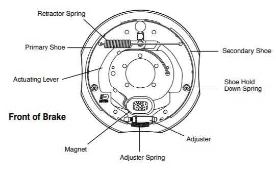
Electrical current is fed into the system by the controller, it flows through the electromagnets in the brakes. The electromagnets are energized and become magnetically attracted to the rotating armature surface of the drums which moves the actuating levers in the direction that the drums are turning. This force causes the actuating cam block at the shoe end of the lever to push the primary shoe out against the inside surface of the brake drum. The force generated by the primary shoe acting through the adjuster moves the secondary shoe out into contact with the brake drum. Increasing the current flow to the electromagnet causes the magnet to grip the armature surface of the brake more firmly. This results in increasing the pressure against the shoes and brake drums until the desired stop is accomplished.
Read all Instructions for Wheel Nut Torque User Manual
alliance RV Valor 2021 Hydraulic Disc Brakes User Manual
alliance RV Valor 2021 Hydraulic Disc Brakes User Manual
Hydraulic Disc Brakes
When equipped, disc brakes have a fixed caliper setup. This setup uses pistons situated on both sides of the rotor. During actuation, hydraulic pressure pushes against the pistons to apply the inboard and outboard brake pads equally to decelerate the spinning rotor. The caliper is fixed and stays stationary during brake actuation and brake adjustment. Brake pad to rotor clearance is maintained as lining wear occurs via the brake piston and internal caliper seal.
 SUSPENSION EQUALIZER SYSTEM
Introduction
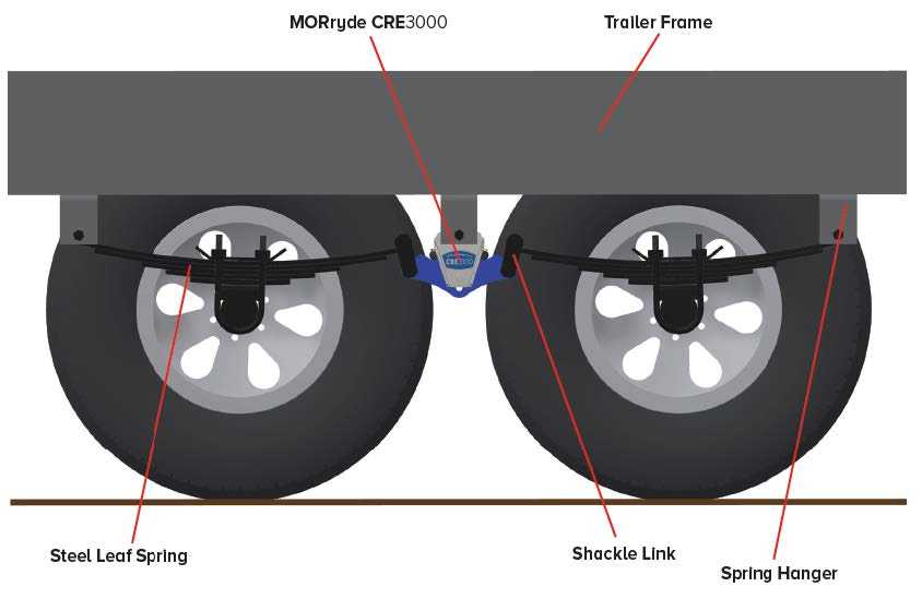
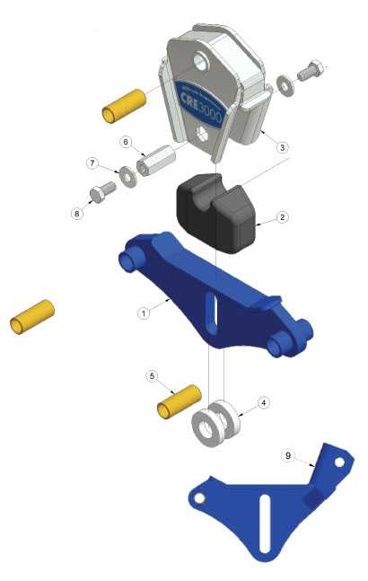
Equipped with dual 7,000 lb Dexter Axles, a MORryde CRE3000 Suspension System and upgraded Wet Bolt Kit w/ heavy duty shackle links, you’ll find that this set up will give you smoother towing than a conventional equalizer and leaf springs and better protection of your RV from damaging road shock.
The CRE3000 is located between the tandem axles, replacing the steel equalizer (see below). Designed uniquely to work with your steel leaf spring suspension to improve overall towing performance.
CRE3000 Parts Breakout:
- Equalizer Beam
- Rubber Compression Spring
- Spring Carrier
- Plastic Glide Pad
- Bronze Bushing
- Hex Coupler Nut
- Washer
- Bolt
- Control Beam
CRE3000 Rubber Shear Spring Inspection
The rubber springs should be periodically inspected for deterioration. If the tabs that protrude from either side of the spring carrier are touching the top of the beam arm, the spring rate of the spring has been affected and the equalizer should be replaced. NOTE: It is normal to see rubber spring weather checking, which is small surface cracks in the rubber, and does not require replacement. It is also common to see minor tearing or cracking of the rubber around the edges.
HD Shackle Links and Wet Bolt Kit


The axles and suspension systems are installed with heavy duty shackle links and greaseable “wet” bolts with bronze bushings for enhanced durability and less maintenance.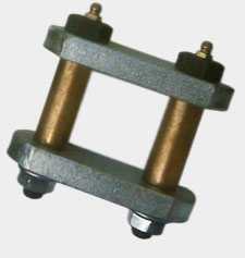
BREAKAWAY SWITCH
The breakaway switch is a critical safety component of the RV brake system. You’ll find this located on or near the fifth wheel pinbox, if the fifth wheel and the tow vehicle become separated during towing, the line will pull the plunger out and immediately activate the trailer’s brakes. Always make sure your breakaway switch is in working order. To test your breakaway switch, while the RV is still hitched to the tow vehicle, disconnect the tow plug from the vehicle and then pull the breakaway pin out, only to the first stage, and you should hear the brakes engage.
CAUTION
NEITHER THE BREAKAWAY SWITCH NOR THE TRAILER BRAKES SHOULD EVER BE USED AS A PARKING BRAKE.
Read all Instructions for Hydraulic Disc Brakes User Manual
alliance RV Valor 2021 Connecting Tow Vehicle User Manual
alliance RV Valor 2021 Connecting Tow Vehicle User Manual
CONNECTING TO THE TOW VEHICLE
Pull Test
WARNING
THE RV BRAKE SYSTEM IS DESIGNED AND RATED FOR THE GVWR OF THE RV, NOT THE GCWR OF THE TOW VEHICLE.
WARNING
WHEN POSSIBLE, ENSURE THAT YOUR HOLDING TANKS ARE EMPTY DURING TRAVEL. FULL HOLDING TANKS CAN ADVERSELY AFFECT THE TOWING OF THE RV.
WARNING
ALWAYS MAKE SURE THE PROPANE IS OFF WHEN TOWING THE RV.
Hitch Receiver
If equipped with a factory hitch receiver, you can tow an additional small trailer behind your RV (if wiring is not included it must be added if a trailer will be towed), such as a boat. Do not use a drawbar longer than 10 inches. The maximum length of the drawbar is from the center of the fastening pin to the center of the ball. The maximum trailer tow rating of the hitch receiver is 3,000 lbs. with a maximum hitch weight of 300 lbs.
The receiver can also be used for a storage rack, bike rack or similar. The cargo weight carrying capacity includes the weight of the cargo carrier and should never exceed 300 lbs. Laws around double towing and overall towing length vary depending on where you live. Consult the appropriate authority for local towing resections in your area.
WARNING
DO NOT EXCEED THE MAXIMUM LOAD OR HITCH WEIGHT RATING OF ANY HITCH KIT. EXCEEDING MAXIMUM LOAD OR WEIGHT RATINGS CAN CREATE A HAZARDOUS CONDITION THAT MAY RESULT IN POSSIBLE DEATH, SERIOUS PERSONAL INJURY, OR SEVERE PRODUCT AND/OR PROPERTY DAMAGE, INCLUDING VOIDING OF THE WARRANTY.
HYDRAULIC LEVELING SYSTEM
Once you get where you’re going, you will need to level your RV. Before you operate the leveling system, make sure that the RV is parked on a level surface and not attached to the tow vehicle. NOTE: Never level the RV with anyone inside.
WARNING
WE RECOMMEND THAT A TRAINED PROFESSIONAL CHANGE THE TIRES ON YOUR RV. THE RV SHOULD ALWAYS BE PROPERLY SUPPORTED WITH JACK STANDS. ATTEMPTS TO CHANGE TIRES OR PERFORM OTHER SERVICE WORK BY THE LEVELING SYSTEM ONLY COULD RESULT IN DEATH OR SERIOUS INJURY.
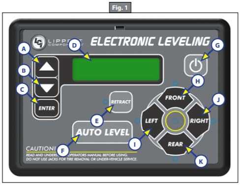
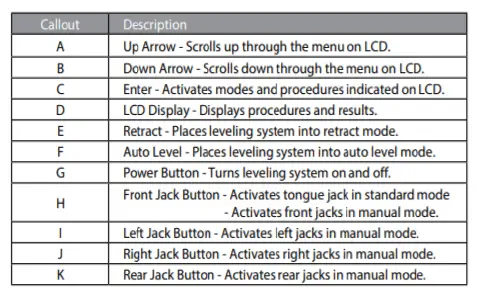
Leveling System Touch Pad
WARNING
Moving parts can pinch, crush or cut. Keep clear and use caution.
Jack Operation
The leveling legs can only be extended when the touch pad is in manual mode. Once in manual mode, pressing the “FRONT” button (Fig. 1H) will extend both front legs at the same time. By pushing the button combination of “FRONT” and “LEFT” (Fig. 1I), or “FRONT” and “RIGHT” (Fig. 1J) buttons, the individual front legs can be extended. Pressing the “REAR” button (Fig. 1K) will extend both rear legs at the same time. To extend individual rear legs, press the button combination of “REAR” and “LEFT” (Fig. 1I), or “REAR” and “RIGHT” (Fig. 1J) buttons, depending on which leg needs to be operated. Pressing the “LEFT” button (Fig. 1I) will extend both the left front leg and the left rear leg. Pressing the “RIGHT” button (Fig. 1J) will extend both the right front leg and the right rear leg.
If the touch pad is put in the retract mode, which is indicated by the orange illuminated LED next to the “RETRACT” button (Fig. 1E), the front legs can be retracted together by pushing the “FRONT” button (Fig. 1H). Individual front legs can be retracted by pushing the combination of the “FRONT” and “LEFT” (Fig. 1I), or “FRONT” and “RIGHT” (Fig. 1J) buttons. The rear legs can be retracted together by pushing the “REAR” button (Fig. 1K), or individually by pushing the combination of the “REAR” and “LEFT” (Fig. 1I) or “REAR” and “RIGHT” (Fig. 1J) buttons. Pressing the “LEFT” button (Fig. 1I) will retract both the left front leg and the left rear leg. Pressing the “RIGHT” button (Fig. 1J) will retract both the right front leg and the right rear leg.
Read all Instructions for Connecting Tow Vehicle User Manual
alliance RV Valor 2021 Auto Level Sequence User Manual
alliance RV Valor 2021 Auto Level Sequence User Manual
Auto Level Sequence
- When auto level begins, the front of the RV will seek a position near a level state.
- The rear legs will then extend and complete the rear leveling sequence.
- When the rear leveling sequence has been completed, the RV will adjust front to back and side to side.
- Each leg will perform a final grounding touch. Once this has been completed the screen will read “AUTO LEVEL SUCCESS.”
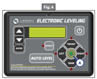
- The LED screen will then read “READY” and also display current battery voltage. The green LED in the center of the four leveling jack buttons will be illuminated (Fig. 4A).
NOTE: If the auto level sequence does not perform as outlined, put the system in manual mode and test that the legs operate correctly by pushing the corresponding buttons on the touch pad. If the jack functions are incorrect, check that the correct jack wiring harnesses are plugged into the correct ports on the controller.
Auto Level Zero Point Calibration
The “Zero Point” is the programmed point to which the 5th Wheel will return whenever the auto-level feature is used. The Zero Point is preset at the factory and should never have to be reset. However, if necessary, Zero Point can be reset.
Note: The Zero Point must be programmed prior to using the auto-level feature to ensure the proper operation of the system. Prior to starting the Zero Point Calibration procedure, check all connections on the controller, valve coils, landing gear, leveling jacks and touchpad.
- Manually run all leveling jacks and landing gear to level the 5th Wheel.
- This is best achieved by placing a level in the center of the 5th Wheel and leveling it both front-to-back and then side-to-side.
- See Basic Jack Operation section for instructions on how to manually operate the system.
- After the 5th Wheel has been leveled, turn off the touchpad.
- With the touchpad off, press and release the FRONT button (Fig. 1G) ten times and then press and release the REAR button (Fig. 1J) ten times.
- The touchpad will flash and beep, then the LCD screen will read “ZERO POINT CALIBRATION ENTER to set, Power to Exit” (Fig. 7).

- To set the current position as the zero point, press the ENTER button (Fig 1C).
A. the LCD screen will read “Zero point stability check” (Fig. 8).
- LCD display will read “Zero point set successfully” once process is complete (Fig. 9).

- The system will set this point as its level state and the touchpad will turn off.
Leveling System Maintenance
WARNING
Failure to follow the instructions provided in this manual may result in death, serious personal injury, severe product, or property damage or voiding of the component warranty.
WARNING
The unit should be supported at both front and rear axles with jack stand before working underneath. Failure to do so may result in death, serious personal injury, severe product or property damage, or voiding of the component warranty.
CAUTION
Always wear eye protection when performing service or maintenance to the unit. Other safety equipment to consider would be hearing protection, gloves and possibly a full‐face shield, depending on the nature of the service.
CAUTION
Moving parts can pinch, crush or cut. Keep clear and use caution.
Maintenance Items
- Dexron III or Mercon V Class “A” automatic transmission fluid
- Electrical contact cleaner
- Lint‐free cloth
- Zip ties
Read all Instructions for Auto Level Sequence User Manual
alliance RV Valor 2021 Emergency Exit User Manual
alliance RV Valor 2021 Emergency Exit User Manual
Emergency Exit Windows
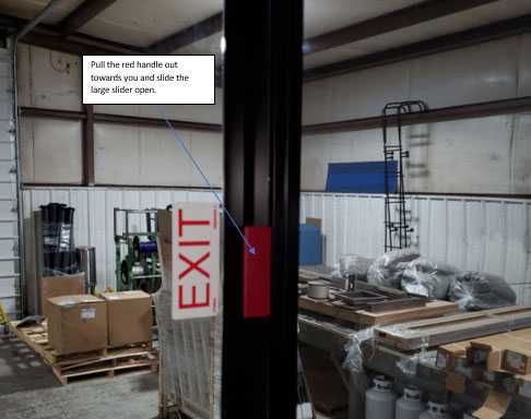
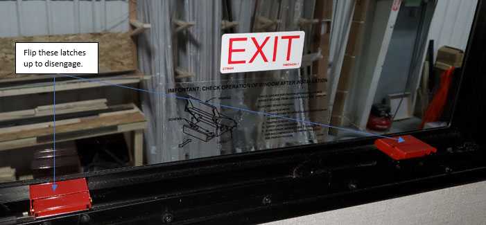
There are two styles of exit windows, both open differently.
- Pull Style Latch: This style is generally used on larger slider style exit windows. Pull the handle out to slide the window open for escape.
- Flip Style Latch: This style flips up and disengages which allows the window to be pushed out for escape.
Fire Safety
Safety is always important, whether you’re at home or on the road. As far as your RV, make sure to keep fire safety a top priority. **In a fire, evacuating all occupants from the RV safely MUST be your top priority!**.
Fire Extinguishers
Classified and rated by fire type, A, B and C. These classifications identify the kinds of fires or burning materials they are designed to fight. A: Trash‐Wood‐Paper – Effective against fires involving paper, wood, textiles and plastics. The primary chemicals used to fight these fires is monoammonium phosphate due to the chemicals ability to smother fires in in these types of materials. B: Liquids – Effective against flammable liquid fires. These can be fires where cooking liquids, oil, gasoline, kerosene or paint have become ignited. The chemicals used in this type of extinguisher are monoammonium phosphate and sodium bicarbonate which induces a chemical reaction which extinguishes the fire. C: Electrical Equipment: ‐ Suitable for fires in “live” electrical equipment. Both monoammonium phosphate and sodium bicarbonate are used in this type of extinguisher due to their nonconductive properties.
WARNING
NEVER TEST OR PRACTICE USING A FIRE EXTINGUISHER BY SQUEEZING THE TRIGGER. THESE ARE NON‐RECHARGEABLE AND ONCE USED, PRESSURE WILL DECREASE OVER TIME AND WILL NOT BE FULLY FUNCTIONAL IN AN EMERGENCY.
WARNING
WHILE USING A FIRE EXTINGUISHER, ALWAYS KEEP YOUR BACK TOWARD A CLEAR PATH FOR EXIT.
WARNING
DO NOT TURN THE ELECTRICAL POWER BACK ON AFTER THE USE OF AN EXTINGUISHER.
WARNING
INSPECT EXTINGUISHERS WEEKLY. IF YOUR RV HAS BEEN IN STORAGE, INSPECT IT BEFORE THE RV IS USED. ALWAYS INSPECT YOUR BEFORE A VACATION OR TRIP WITH YOUR RV.
Fire Extinguishers
A common acronym for proper fire extinguisher operation is P.A.S.S.
- Pull the pin
- Aim the nozzle (always aim at the base of the fire, not the flames)
- Squeeze the trigger
- Sweep from side to side
For additional information on fire extinguisher operation, please refer to the fire extinguishers user’s manual.
Smoke & CO/Carbon Monoxide Alarms
Your RV is equipped with a smoke & CO/Carbon Monoxide combination alarm. Understanding the information in this section will prepare you to reach in the event of an emergency.
Follow safety rules and prevent hazardous situations:
- NEVER smoke in bed.
- Keep matches or lighters away from children.
- Store flammable materials in proper containers.
- Keep electrical appliances in good condition and NEVER overload electrical circuits.
- Keep stove debris free.
- Never leave anything cooking on the stove unattended.
- Keep portable heaters and open flames, such as candles, away from flammable materials.
- Don’t let rubbish accumulate.
Read all Instructions for Emergency Exit User Manual
alliance RV Valor 2021 Alarm Maintenance User Manual
alliance RV Valor 2021 Alarm Maintenance User Manual
Propane (LP) Alarm Maintenance
Test all alarms weekly. Vacuum the dust off of the alarm cover. If cleaning is needed, clean with a water damp cloth. Do NOT spray cleaning agents or waxes directly onto the front panel. This can cause damage to the alarm.
WARNING
THE CO ALARM WILL NOT OPERATE WITHOUT BATTERIES
WARNING
NEVER ATTEMPT TO REPAIR AN ALARM, IMMEDIATELY HAVE THE ALARM REPLACED.
EXTENDED RECREATIONAL USE OF THE RV
In some cases you may find yourself in the RV for extended periods of time. Whether that be full time living, a long weekend or an extended stay, you may run into some challenges. We have put together some helpful tips for battling some of these challenges.
Condensation & Mold
The normal living activities of even a few people in an RV can lead to rapid moisture saturation of the air inside the RV as well as accelerated wear and tear. This condensation, if left unaddressed, can lead to mold. A more aggressive maintenace schedule may need to be adopted. Below are some pointers to assist with some of the problems you may face while using the RV for extended periods of time.
- Use a dehumidifier.
- Use exhaust fans when showering and cooking.
- In warmer temperatures, use your air conditioner.
- Crack windows.
- Don’t air dry clothes in the RV.
- Implement proper preventative maintenance and overall RV cleanliness.
WARNING
CONDENSATION MAY CAUSE DAMPNESS, MILDEW AND MOLD. IF NOT ADDRESSED IMMEDIATELY, CAN RESULT IN DAMAGE AND POSSIBLY LEAD TO ADDITIONAL MOLD OR MILDEW ISSUES WHICH CAN BE HAZARDOUS TO YOUR HEALTH.
Exterior Plumbing
Alliance RVs are equipped with heating pads for the holding tanks and a dedicated heat vent to drop air down into the underbelly. Depending on your needs, it may be necessary for you to take additional protection steps. Keeping your water running and the additional use of heat tape on pipes, hoses, fresh water and sewer lines will all assist in keeping your RV safe from damage during use in freezing temperatures. If your RV will not be used in cold weather, ALWAYS have your RV winterized (covered in the plumbing section of this manual).
Formaldehyde
Formaldehyde is used in many products such as glues, fabrics, paint coatings, and even paper products. Formaldehyde is also released from many smoking, cooking, soaps, and many other household products. While most of the formaldehyde used in products in construction is consumed during the manufacturing process, a very small amount remains. This leftover formaldehyde dissipates over time as it works its way out of the product. Proper ventilation by way of the available vents, fans, and air conditioning units in your RV is key. If you have any additional questions, please do not hesitate to contact Alliance RV.
PROPANE SAFETY
About the Propane System
The propane system provides heat, hot water, fuel for cooking, and refrigeration and can be used for other small appliances. The propane supply for an RV is stored in a DOT cylinder that is positioned vertically upright and mounted outside the living space of an RV. Repair and/or replacement should always be done by certified service technicians. Make sure your propane system is inspected at least annually by a certified service technician. They are trained to detect incorrect tank pressure, leaks, or other potential hazards and address them properly. Do not connect your propane system to another gas source or attempt to repair any propane-related component yourself.
IF YOU SMELL PROPANE:
- EXTINGUISH ANY OPEN FLAMES INCLUDING PILOT LIGHTS AND ALL SMOKING MATERIALS.
- SHUT OFF THE PROPANE SUPPLY AT THE LP CONTAINERS.
- DO NOT TOUCH ELECTRICAL SWITCHES.
- OPEN DOORS AND OTHER VENTS.
- LEAVE THE AREA UNTIL THE ODOR CLEARS.
- THE PROPANE SYSTEM SHOULD BE CHECKED FOR LEAKS AND THE SOURCE DETECTED AND REPAIRED BEFORE USING THE RV AGAIN.
- FAILURE TO COMPLY COULD RESULT IN AN EXPLOSION RESULTING IN DEATH OR SERIOUS INJURY.
NEVER USE AN OPEN FLAME TO TEST FOR A PROPANE LEAK. DO NOT CHECK FOR LEAKS USING PRODUCTS THAT CONTAIN AMMONIA OR CHLORINE, THESE PRODUCTS CAN CAUSE CRACKS TO FORM ON METAL COMPONENTS IN THE PROPANE SYSTEM. A SOLUTION OF WATER AN MILD SOAP SHOULD BE USED BY SPRAYING THE FITTINGS AND CONNECTION POINTS DOWN AND WATCHING FOR BUBBLES.
WARNING
DOT PROPANE TANKS MUST BE TRANSPORTED AND STORED IN AN UPRIGHT POSITION SO THE PRESSURE RELIEF VALVE CAN FUNCTION PROPERLY. LAYING A TANK ON ITS SIDE MAY CREATE A VERY DANGEROUS SITUATION. THE LP PIGTAIL HOSE MUST BE INSTALLED IN A MANNER TO AVOID TENSION OR STRESS AT EITHER END OF THE HOSE. KEEP THE PIGTAIL AWAY FROM SHARP EDGES,RIGID CORNERS, WALLS, AND DOORS. BEFORE ENTERING A PROPANE FUEL SERVICE STATION MAKE SURE ALL PILOT LIGHTS ARE EXTINGUISHED. SHUT THE GAS TO ALL APPLIANCES OFF BY TURNING OFF THE PROPANE AT THE GAS SHUT-OFF VALVE(S). ALWAYS SHUT OFF ANY ENGINE BEFORE REFUELING. DO NOT SMOKE AND NEVER OPERATE IGNITION SOURCES WHILE REFUELING.
Read all Instructions for Alarm Maintenance User Manual
alliance RV Valor 2021 Traveling with Propane User Manual
alliance RV Valor 2021 Traveling with Propane User Manual
Traveling with Propane
Turning the propane off when traveling is always safer, it reduces the risk of a gas leak from a line or connection working loose. Some states have laws against traveling with propane on. Make sure you are familiar with those laws and regulations in the area you are traveling.
WARNING
MAKE SURE ALL PROPANE TANK FASTENERS ARE SECURED BEFORE TRAVELING.
LP Automatic Changeover Regulator
To regulate the propane pressure, an RV is equipped with a two‐stage regulator with automatic changeover. With the first stage of the regulator, the fuel coming from the tank is reduced by venting from the high pressure the LP is compressed under for storage and takes it down to 10 to 15 psi. In the second stage, the pressure is reduced again by further venting down to 11” water column which is the pressure safe for the appliances that the propane system powers. Always make sure that the vents are clean and unobstructed.
LP Automatic Changeover Regulator
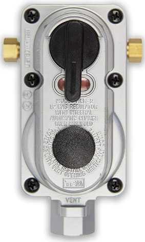
This regulator allows for the removal of empty cylinders for refill without interrupting the propane supply and will automatically switch from the supplying tank to the reserve tank when empty.
WARNING
PROPANE CONNECTIONS SHOULD BE CHECKED PERIODICALLY AS VIBRATIONS FROM TRAVEL MAY CAUSE THEM TO LOOSEN. FAILURE TO CHECK THESE CONNECTIONS COULD LEAD TO A PROPANE LEAK. A LEAK CAN CAUSE A FIRE OR EXPLOSION.

Propane System Maintenance
Routinely visually inspect your propane cylinders, mounting hardware, supply lines, and connection points for wear, rust, kinks or damage. The propane system should be serviced by a qualified technician immediately upon an issue being identified. Never paint propane cylinders, valves or mounting hardware. Your RVs propane system should be inspected by a certified professional at least once a year. Never attempt to repair any propane-related component yourself. Always make sure your RVs fire extinguisher, CO, gas, and smoke detectors are in working order. Do this by regularly testing your alarms and safety items. An alarm or extinguisher that is not working should be replaced immediately.
WARNING
NEVER ATTEMPT TO REPAIR ANY PROPANE-RELATED COMPONENT. ENSURE THAT ALL ALARMS, DETECTORS, AND EXTINGUISHERS ARE IN GOOD WORKING ORDER.
Filling Your Propane Tanks
Your Alliance RV uses DOT cylinders. These cylinders can be removed and taken to a propane dealer for refilling. A propane tank can only be filled to 80% of its total capacity. The remaining 20% is for expansion that takes place when subjected to heat. If a tank is filled to 80% when it is cold outside, that same tank may be at 90% on a much warmer day. Always ensure that the tank is filled to the required limit only.
Read all Instructions for Traveling with Propane User Manual
alliance RV Valor 2021 BEFORE Filling Fuel Tank User Manual
alliance RV Valor 2021 BEFORE Filling Fuel Tank User Manual
BEFORE Filling the Fuel Station Tank(s)
- Level your RV from side‐to‐side and front‐to‐back.
- When the gas station pump shuts off, STOP fueling.
- Overfilling the tank(s) may result in fuel leakage and damage to the fuel station components.
- BE CAREFUL not to contaminate fuel with debris while the filler cap is removed.
- Replace the filler cap immediately when finished fueling.
Filling the Fuel Tanks:
- The LEFT fuel filler cap is the GENERATOR fuel tank, (Nearest the front of the RV)
- The RIGHT fuel filler cap is the PUMP fuel tank. (Nearest the rear of the RV)
- The fuel tanks are made for Unleaded Gas ONLY.
- ALWAYS use clean, fresh unleaded gasoline.
- Gas blends cannot contain more than 15% Ethanol.
- The fuel tank(s) are not compatible with other fuel blends or diesel fuel.
NOTE: DO NOT over‐fill and DO NOT top‐off the fuel tank(s).
Fuel Station Control Panel
This control panel, located in a lockable box near the exterior fuel fills, contains the ON/OFF switch for the fuel pump, and fuel gauges showing the amount of gasoline in each of the fuel tank(s).
Turning ON & UNLOCKING Fuel Station Control Panel:
- After being INACTIVE, the control panel will be in Sleep/Locked Mode
- Lights on the control panel are not lit up (sleep mode).
- ON/OFF buttons are not functional.
- WAKE control panel by pressing “ON” or “OFF” button.
- Control panel will display fuel levels
- UNLOCK control panel by holding “OFF” button down until “ON” button begins to blink
- Press “ON” button to activate pump.
Dispensing Fuel
NO SMOKING
Before dispensing fuel, turn off all engines, fuel-burning appliances, and their igniters. (See operating instructions)
DO NOT dispense fuel within 20 ft (6.1 m) of an ignition source. Can cause ignition of flammable vapors, which can lead to a fire or explosion and result in death or serious injury.
CAUTION
- ALWAYS turn OFF the Fuel Pump Switch in the event of an Emergency or spill.
- ALWAYS turn OFF the Fuel Pump Switch when the fuel station is not in use.
- Open the compartment containing the fuel pump nozzle and hose.
- Insert the fuel pump nozzle into the receiving tank.
- Access the Fuel Station Control Panel and turn the pump ON
- ALWAYS keep the nozzle in contact with the tank fill opening of the vehicle or equipment being filled.
- Squeeze the nozzle handle to begin the flow of fuel.
- Release the nozzle’s handle to stop the flow of fuel.
- Turn OFF the Pump Switch.
DANGER
VEHICLES AND EQUIPMENT POWERED BY INTERNAL COMBUSTION ENGINES AND PLACED IN RVS MAY CAUSE CARBON MONOXIDE POISONING OR ASPHYXIATION, WHICH COULD RESULT IN DEATH OR SERIOUS INJURY. THE FLAMMABLE LIQUIDS USED TO POWER THESE ITEMS CAN CAUSE A FIRE OR EXPLOSION, WHICH CAN RESULT IN DEATH OR SERIOUS INJURY.
Read all Instructions for BEFORE Filling Fuel Tank User Manual
alliance RV Valor 2021 Ramp Door Patio Package User Manual
alliance RV Valor 2021 Ramp Door Patio Package
Ramp Door Patio Package w
Ramp Door Patio Package w/Step (If So Equipped)
Units equipped with a Ramp Door Patio Package feature folding rails and detachable steps. Caution should be taken NOT to exceed the ramp door weight capacities when in either the ramp position or the patio deck position, and to maintain even weight distribution.
WARNING
- PATIO HAS A MAXIMUM CAPACITY OF 10 PERSONS OR 1,500 LBS. MAXIMUM. THE TOTAL WEIGHT OF THE PATIO MUST REMAIN WITHIN THE 1,500 LB. LIMIT.
- STABILIZER JACKS MUST BE USED WHEN THE RAMP DOOR IS IN THE PATIO POSITION.
- SUPPORT JACKS ON THE PATIO DOOR MUST BE USED WHERE APPLICABLE.
- EXCEEDING THE LOAD LIMIT MAY LEAD TO COLLAPSE AND POSSIBLE PERSONAL INJURY.
- MAXIMUM CAPACITY IS BASED ON AN EVENLY DISTRIBUTED LOAD IN THE PATIO POSITION PERSONAL INJURY.
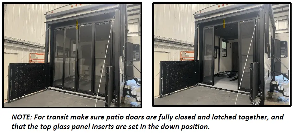
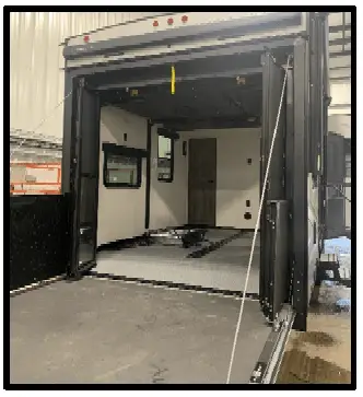
Setting Up the Ramp Door Patio and Railing System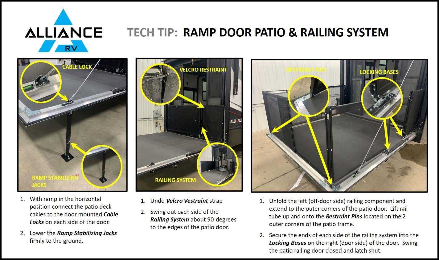
ALWAYS follow all instructions and safety labels while using your Ramp Door / Patio Deck.
GARAGE AREA (CONTINUED)
3 Seasons Patio Door (If So Equipped)
The garage 3‐seasons patio door features a 4‐panel design with sliding glass inserts to allow airflow.
- The center doors slide open to provide a passage way from the garage to the ramp door/patio.
- For full width access to the garage area, the panels can be unlatched with a pullcord at the top of the doors, and are designed to swing outward 90 degrees.
Retractable Screen Wall (If So Equipped)
Make sure that all obstacles are removed from the path of the screen wall. Grip the screen wall pull bar and pull down until fully extended to the garage floor. To store the screen wall, a quick downward tug on the pull bar handle will release and allow it to retract back up.
Happi Jac Power Bed Lift
The Hippias power bed lift system supports the two beds which can be raised up and out of the way while storing or hauling cargo in the garage area, and lowered again for use when needed.
WARNING
RAISE THE REAR BED TO THE HIGHEST POSITION WHEN TOWING YOUR RV. DAMAGE TO THE REAR BED MAY RESULT FROM TRAVELING WITH THE BED IN THE LOWERED POSITION.
WARNING
DO NOT LOAD MORE THAN 600 LBS ON THE BED. DAMAGE TO THE BED LIFT MECHANISM AND PERSONAL INJURY MAY RESULT FROM OVERLOADING.
Operating Precautions:
- CHECK to make sure the attaching pins are securely fastened to all four corners of the bed platform before towing the trailer, or using the bed(s).
- ALWAYS raise the bed(s) to the full up position when the trailer is being towed to avoid damage to the bed lift system as a result of bouncing.
- ALWAYS make sure that the areas above, below and adjacent to the bed(s) are free from obstructions before operating the bed(s).
- ALWAYS check before operating bed(s) to ensure that there is nothing interfering with the travel of the chain mechanism inside the c‐channel.
- ALWAYS use care when loading cargo/vehicles in the bed area. This is to avoid damage to the bed mechanism.
- ALWAYS properly secure loads in the bed area to avoid damage to the bed mechanism from shifting or falling loads.
- NEVER operate the bed(s) with any items other than bedding on the bed platform(s).
- NEVER travel with any items other than bedding on the bed(s). Loose items can become projectiles.
- NEVER operate the bed(s) when persons or pets are on the bed platform.
- NEVER hang from, or hang more than 20 pounds, on the cross‐connecting shaft.
Read all Instructions for Ramp Door Patio Package User Manual
alliance RV Valor 2021 Slideout Safety Information User Manual
alliance RV Valor 2021 Slideout Safety Information User Manual
Slideout Safety Information
WARNING
FAILURE TO ADHERE WITH THE FOLLOWING IN FORMATION MAY RESULT IN DEATH, SERIOUS INJURY, RV OR OTHER PROPERTY DAMAGE.
All slideout systems are intended solely for opening and closing the slideout room and should never be used for any other purpose. Before operating your slideout,
please keep these things in mind:
- Your location should be clear of obstructions that may cause damage when the slideout room is operated.
- Be sure that everyone is clear of the RV prior to the slideout room actuation.
- Keep parts away from slideout mechanisms during use. Severe injury or death may result.
- Park your RV on solid and level ground.
CAUTION
ALWAYS ENSURE THE SLIDEOUT PATH IS CLEAR DURING OPERATION. KEEP CLEAR OF SLIDE RAILS WHEN THE ROOM IS IN MOTION. THE GEAR ASSEMBLY MAY PINCH OR CATCH ON LOOSE CLOTHING AND CAUSE PERSONAL INJURY.
EXACT‐SLIDE Flush Floor Slideout System
Alliance RV utilizes the EXACT‐SLIDE by BAL for select main floor slideouts. This is a cable‐driven system that is operated by dual 12V DC electric motors.
We recommend that the moving parts be kept clean. They can be washed with mild soap and water. No grease or lubrication is necessary. All slideouts are independently switched and operated at the central monitor panel shown below. This panel will be found relatively close to the entry door of the RV in a cabinet designed to house this panel. Location will vary depending on floor plan of your RV.
Operating Your EXACT‐SLIDE Slideout System
Extending EXACT‐SLIDE Flush Floor Slideout
- Level the RV.
- Verify the battery is fully charged.
- Press and hold the rooms switch in the “OUT” position until room is fully extended and stops moving. Holding the switch down until the control automatically turns each motor off will result in the best sealing position.
Retracting Your EXACT‐SLIDE Flush Floor Slideout
- Verify the battery is fully charged.
- Press and hold the room’s switch in the “IN” position until the room is fully retracted and stops moving. Holding the switch down until the controller automatically turns each motor off will result in the best sealing position.
EXACT‐SLIDE System Overview

EXACT‐SLIDE Slideout Maintenance
- Periodically inspect your cables for sagging or fraying. The system is designed to function properly with minimal pretension on the cables.
- If cable adjustment or replacement is necessary, it should be performed by an authorized dealer.
The slideouts need a full battery for operation. The battery should be maintained in accordance with the battery manufacturer’s recommendations. Always check the terminals and other connections at the battery, the control switch, and the system for corrosion, and loose or damaged terminals. Check motor leads under the trailer chassis, these connections are subject to damage from road debris.
EXACT‐SLIDE Slideout Manual Override
In the event that power is lost to the slide‐out motor(s), the slide‐out room can be manually retracted by following these steps:
- Use a flex shaft and #3 square bit.
- Locate each motor at the top of the mechanism. Insert the drive bit into the end of the motor and activate with a cordless drill (DO NOT USE AN IMPACT DRIVER).
- Alternate between motors so that the room does not become wedged in the opening or encounter cabinets or other fixtures inside the RV.
Read all Instructions for Slideout Safety Information User Manual
alliance RV Valor 2021 In‐Wall Electric Slideout User Manual
alliance RV Valor 2021 In‐Wall Electric Slideout User Manual
In‐Wall Electric Slide out System
The In‐Wall electric slide out system is used in the upstairs portion of the RV, typically a bedroom slide out. All slide outs are operated at the central monitor panel shown below. This panel will be found relatively close to the entry door of the RV in a cabinet designed to house this panel. The slide out system should never be used for anything other purpose other than extending and retracting the slide out room itself. To use the system for any reason other than what it is designed for may result in death, serious injury or damage to the coach.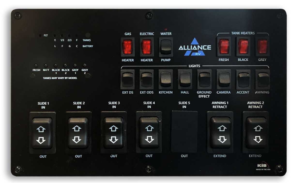
Operating Your In‐Wall Slide-out System
- Level the RV.
- Verify the battery is fully charged.
- Press and hold the room’s switch in the “OUT” position until the room is fully extended and stops moving.
- Release the switch, this will lock the room in the “OUT” position.
Retracting Your In‐Wall Electric Slideout
- Verify the battery is fully charged.
- Press and hold the room’s switch in the “IN” position until the room is fully retracted and stops moving.
- Release the switch, this will lock the room in the “IN” position.
NOTE:
It is important to continue to press the slideout switch for a few seconds after the room is fully extended until the motor shuts off. The control will sense the room has stopped and shut the motor off automatically.
SLIDEOUTS (CONTINUED)
In‐Wall Electric Slide-out Controller Overview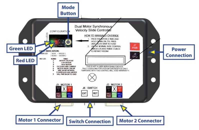
- Status LEDs: 2 LEDs, 1 green and 1 red are provided to indicate the current controller status and faults.
- Mode Button: Used to engage the electronic manual override.
- Power Connection: 12V DC input. Unit will operate from 8V DC to 18V DC.
- Switch Connection: Spade connection for the switch wiring.
- Motor 1 Connector: Power and encoder input for motor 1.
- Motor 2 Connector: Power and encoder input for motor 2.
In‐Wall Electric Slide out Controller Connections
- Connections & Motor Harness

NOTE: Motor harnesses have Molex connectors at the controller and a molded connector at the motor end (2 images shown above). Wire colors match with color codes on the control board. It does not matter which motor is 1 or 2.
In‐Wall Electric Slide-out System Overview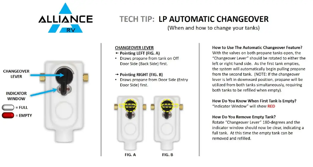
In‐Wall Electric Slide out Motor and Harnesses Check for proper connections between the motors and harnesses. Visually inspect the exposed harnesses to ensure they are not pinched or damaged.
Note: Ribs on motor connector lineup with notch inside of female connector on the wiring harness. Color codes on wires also match (black to black, red to red, etc.).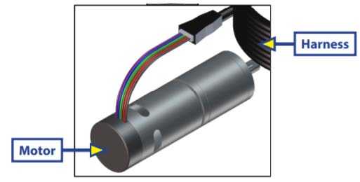 Adjusting / Resynchronizing the In‐Wall Electric Slide out Motors
- Run the slide out room all the way out.
NOTE: Keep the switch pressed until the motors shut down on their own. - Bring the slideout back in 1‐2 inches.
- Repeat steps 1 and 2 until both motors shut down at the same time.
NOTE: It can take 3 or more attempts to successfully re‐sync the room. - Run the slide out all the way out.
NOTE: Keep the switch pressed until the motors shut down on their own. Fully retract the slide out again. When both motors shut down at the same time at full extension and full retraction, the room is properly synced. If they do not shut down at the same time, repeat the process until they do.
In‐Wall Electric Slide out Troubleshooting
The electric slide-out requires a minimum of a 30‐amp circuit breaker. Check the 12‐volt distribution center for blown circuit breakers and replace any if necessary. If the circuit breaker blows immediately upon replacement, there is a problem with the wiring to slide out the controller. Check outside the RV for obstructions. Check inside the RV for any obstructions. Also, check for smaller objects that may be wedged under the floor or in the sides of unit. Remove any obstructions that exist. Check the sides of the slide room for any dirt or debris. Small dirt clumps or metal shavings can cause the spur gear to bind up and stop the slide out from moving. Use an air compressor or a dry brush to remove any dirt or debris from the rack before attempting to use slide out again. During operation when an error occurs, the board will use the LEDs to indicate where the problem exists (shown below).
Read all Instructions for In‐Wall Electric Slideout User Manual
alliance RV Valor 2021 Electrical Overview User Manual
alliance RV Valor 2021 Electrical Overview User Guide
Electrical Overview
Your RV has a 12‐volt electrical system and a 120‐volt system. The 12‐volt system is powered by battery and powers items such as the water heater, furnace, and refrigerators, as well as most of the lights. Water pumps, carbon monoxide detectors, and a number of other items will also be powered by the 12‐volt system. You’ll also find that Alliance RV has a conveniently color-coded and numbered 12‐volt wiring system. The 120‐volt system is powered by an electrical source via your power cord, a generator and in some cases, an inverter (which converts 12 volts to assist in powering the 120-volt system), and typically powers kitchen appliances, TVs, and other electrical appliances. Alliance RV is compliant with industry standards applicable at the time the RV is manufactured. Do not make unauthorized changes.
WARNING
CHANGES OR ADDITIONS MADE AFTER DELIVERY MAY RESULT IN HAZARDOUS CONDITIONS. ALWAYS HAVE A PROFESSIONAL WORK ON YOUR RV.
Modifications to the RVs electrical system should only be performed by qualified technicians and should never be made without approval from Alliance RV. Should a modification be made, those changes MUST comply with current safety and code requirements.
WARNING
USE THE CATION WHEN USING METAL TOOLS. IF A TOOL CONTACTS A BATTERY TERMINAL OR METAL CONNECTED TO IT, A SHORT CIRCUIT COULD OCCUR AND CAUSE INJURY.
Before working on the electrical system:
- Make sure the inverter (if equipped), is turned off before disconnecting the batteries.
- Disconnect the power cord.
- Turn off the generator (if equipped) and disable the auto start function (if equipped).
- Turn off the battery disconnect switch.
- Turn off the 120‐volt AC main circuit breaker.
- Disconnect the negative 12‐volt DC battery terminal from the battery.
Power Converter
The INTELI‐POWER series converter will supply “clean” power from input voltages that range from 105 ‐ 130VAC. The INTELI‐POWER series of converters are primarily designed for use with a battery; however, the output of the INTELI‐POWER converters is a regulated, filtered DC voltage that can power sensitive electronics without the need for a battery or other filtering. At normal input voltages (105 – 130VAC) the full load-rated capacity is available. At input voltages less than 105 VAC the converter may not supply full rated output capacity.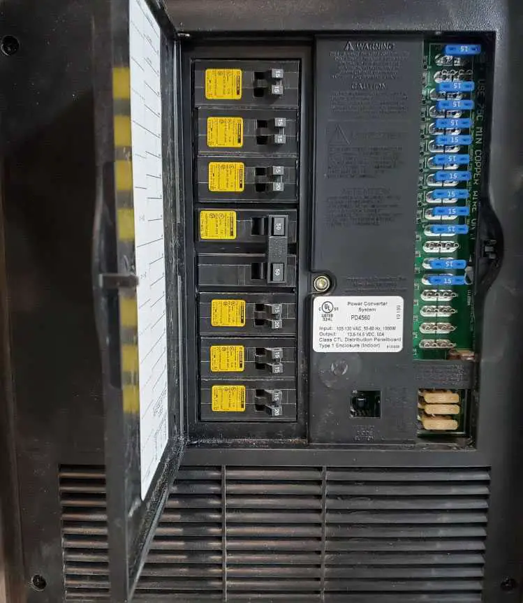
PD4500 Series ‐ The full rated load is available for load, battery charging or both. When functioning as a regulated battery charger the converter has a nominal voltage output of 13.6 VDC. The system is designed to sense voltage on the battery and automatically selects one of three operating modes (normal, boost and storage) to provide the correct charge level to the batteries.
Power Control Center
- NORMAL MODE: Output voltage set at approximately VDC.
- BOOST MODE: If the converter senses that the battery voltage has dropped below a preset level the output voltage is increased to approximately 14.4 VDC to rapidly recharge the battery.
- STORAGE MODE: When there has been no significant battery usage for 30 hours the output voltage is reduced to 13.2 VDC for minimal water usage. When in storage mode, the output voltage will periodically increase to 14.4 VDC to help prevent sulfating of the battery plates.
WARNING
IT IS IMPORTANT THAT THE FLUID LEVELS OF ANY CONNECTED BATTERY(S) BE CHECKED ON A REGULAR BASIS. ALL BATTERIES WILL “GAS” AND LOSE SOME FLUID WHEN CONTINUOUSLY CONNECTED TO ANY CHARGING SOURCE.
Read all Instructions for Electrical Overview User Manual
alliance RV Valor 2021 Energy Management User Manual
alliance RV Valor 2021 Energy Management User Manual
Energy Management System
Energy Management System (If so equipped)
The Intellitronix Energy Management System combines a standard breaker box with automatic power management for use in a recreational vehicle. It automatically senses and shifts AC loads to best utilize the available power. It decides what AC circuits get power based on user priority settings. For example, if someone is using a hair dryer and running a microwave oven and toaster, and the refrigerator starts running, that may temporarily be more power than is available, potentially causing a main circuit breaker to trip, or overloading a generator. The Intellitronix Energy Management System can temporarily shut down the refrigerator power. When enough appliances are turned off, and sufficient power is available, refrigerator power is automatically restored. It also functions as a standard breaker box using standard breakers and wiring.
ELECTRICAL
Energy Management System (If So Equipped)
Control Panel
The green LEDs indicate which circuits are on. There are six main menu displays accessed by pressing the “Up” or “Down” arrow buttons.
Total Power Display
Pressing Enter at the Total Power Display, (“Enter for Reset”) asks “Reset? Y/N N” press Up or Down buttons until “Reset? Y/N Y” appears. Then press the Enter button. It will show “Resetting… “ for a few seconds. Any lines that were powered off are all powered on. This is like resetting a breaker. It assumes you have reduced the load that had previously turned off some lines.
History Menu
Pressing Enter at the History Menu shows past power consumption in Watt hours per circuit, the first display will show circuits 1 2 3, next display shows circuits 4 5 6, then previous hours as you press the “Down” button. Pressing the Enter button again returns you to the History Menu screen.
Max Power Setting Display
Pressing Enter at the Max Power Setting Display allows editing of the maximum Amps allowed by the system. Press Up or Down to set Amps, then Enter to save.
Circuit Priority Display
Pressing Enter at the Circuit Priority Display allows editing of circuit priorities. An arrow appears beside each priority number as you continue to press the Enter button. Pressing the Up or Down buttons changes the priority pointed to by the arrow. A circuit at priority level “1” will be turned off last. Priority level “6” is turned off first when too much power is being used. The default setting is “1 2 3 4 5 6” and indicates the first circuit (far left) has the most priority and the sixth circuit (far right) has the least priority. A setting of “6 2 3 4 5 1” indicates the first circuit (far left) has the least priority and the sixth circuit (far right) has the most priority.
Present Wattage Display
Read all Instructions for Energy Management User Manual
alliance RV Valor 2021 Power Cord User Manual
alliance RV Valor 2021 Power Cord User Manual
Power Cord
- DO NOT plug your RV 50‐amp shore cord into any receptacle that is not wired to National Electric Code for 50 amp 120/240V configuration. Doing so will supply the RV with the incorrect electrical power causing extensive damage to the electrical system and 120‐volt components which would not be warrantable.
- DO NOT disconnect the 50‐amp male plug connection by pulling up on the cord. This will cause a loss of neutral and 240 volts AC will be supplied to the electrical system and 120‐volt components causing extensive damage which would not be warrantable. Always pull straight out on the head of the cord so all 4 prongs disengage the receptacle simultaneously.
- DO NOT plug in or unplug the shore cord while under load. Make sure all 120‐volt components are turned off prior to connecting or disconnecting the shore cord or damage to the 120‐volt systems may result. Turn off the breakers at the power center first before connecting or disconnecting the shore cord to prevent damage.
WARNING
- FAILURE TO PLUG YOUR 50 AMP POWER CORD INTO A RECEPTACLE THAT IS NOT WIRED TO THE NATIONAL ELECTRIC CODE FOR 50 AMP 120/140V CONFIGURATION COULD LEAD
TO AN INCREASED RISK OF PROPERY DAMAGE, SERIOUS INJURY OR DEATH. - IT IS IMPORTANT TO INSPECT THE POWER CORD FREQUENTLY FOR DAMAGE. IF DAMAGE IS FOUND, HAVE THE CORD REPLACED IMMEDIATELY
WARNING
EXPOSURE TO VOLTAGES HIGHER OR LOWER THAN A NOMINAL 120‐VOLTS, WILL DAMAGE OR SHORTEN THE SERVICE LIFE OF THE ELECTRICAL SYSTEM AND APPLIANCES. THE 50 AMP 120‐VOLT 60HZ AC ELECTRICAL SYSTEM CAN BE POWERED BY AN OUTSIDE 120/240‐VOLT 60HZ UTILITY SERVICE LIKE THOSE COMMONLY FOUND IN CAMPGROUNDS OR BY 120/240‐VOLT 60HZ GENERATOR POWER
WARNING
- MAKE CERTAIN THE EXTERNAL POWER SOURCE YOU CONNECT THE POWER CORD TO IS A PROPERLY WIRED 50 AMP NEMA 14‐50 RV RECEPTACLE AND NOT 240 VOLT AC. PLUG INTO 50‐AMP SERVICE ONLY
- CIRCUIT BREAKERS AND FUSES WILL NOT OFFER COMPLETE PROTECTION OF THE ELECTRICAL SYSTEM IN THE EVENT OF A POWER SURGE OR VOLTAGE SPIKE
120‐Volt Circuit Breakers
Your 120V circuit breakers are in the main power control center. These circuit breakers act just like those in a household in that they protect all the 120V wiring and components. You’ll find the individual circuits labeled to identify which each breaker is for. To reset a breaker, simply flip the switch to the off position and then immediately back to the on position. If the breaker immediately trips again, contact your dealer or Alliance RV for assistance.
Circuit breakers can wear out so an annual check to ensure the operation is good may be needed. Only replace circuit breakers with those of the same specified type, voltage, and current rating. NEVER replace a circuit breaker with one listed at a higher amperage rating.
WARNING
- CIRCUIT BREAKERS AND FUSES WILL NOT OFFER COMPLETE PROTECTION OF THE ELECTRICAL SYSTEM IN THE EVENT OF A POWER SURGE OR VOLTAGE SPIKE
- REPLACEMENT CIRCUIT BREAKERS MUST BE OF THE SAME VOLTAGE, AMPERAGE RATING, AND TYPE. NEVER USE A HIGHER-RATED REPLACEMENT CIRCUIT BREAKER, DOING SO MAY CAUSE A FIRE BY OVERHEATING THE RV WIRING
At the beginning of the camping season, inspect the circuit breakers and replace them as needed. Test by turning each circuit breaker off and back on, circuit breakers are wearable parts and must be replaced as needed as part of your RV maintenance.
12 Volt Fuse Panel
You’ll find the 12‐volt fuse panel in the main power control center (mentioned above). When replacing fuses, please follow these safety precautions:
- Disconnect the power cord.
- Turn the inverter off.
- Disconnect batteries.
Read all Instructions for Power Cord User Manual
alliance RV Valor 2021 Charging Battery User Manual
2021 alliance RV Valor Charging Battery User Guide
Charging the Battery
During standard charging, the battery is first charged at 20A constant current until the battery reaches 14.4V. Then, the battery is charged at a constant voltage of 14.4V while tapering the charging current. Charging is considered complete when the current is less than 2A. However, leaving the battery on float will continue to balance the cells and will not harm the battery. Safe charging requires temperatures between O° C and 55° C (32° F and 131° F) and takes approximately 7 Hours.
CAUTION
- DO NOT exceed maximum charging current to the battery.
- ONLY charge the battery with a battery charger or charge controller that is compatible with lithium iron phosphate batteries.
Discharging the Battery
During standard discharging, battery is discharged at 20A constant current until the battery reaches 1 0V. Safe discharging requires temperatures between ‐20° C and 60° C (‐4° Fand 140° F).
CAUTION
- DO NOT exceed maximum discharging current to the battery.
- DO NOT connect large loads to the battery when the battery is running low.
- If the battery shuts off due to low state of charge (SoC), please disconnect the battery from your equipment to eliminate potential parasitic loads and recharge the battery as soon as possible. Failure to do so may cause irreversible damage to the battery.
- It is highly recommended to pair the battery with low voltage disconnect devices in the system setup.
Battery Maintenance
Inspection: Please perform regular visual inspection by following these steps:
- Examine the external appearance of the battery. The top of the battery and terminal connections should be clean, dry, and free of corrosion.
- Check battery cables and connections. Replace any damaged cables and tighten any loose connections.
Cleaning: Please clean the battery at regular intervals by following these steps:
- Disconnect the battery from your charging source or load.
- Put the battery in shelf mode using the Activation Switch
- Clean the top of the battery, terminals, and connections with a damp cloth or non‐metallic brush. If the battery is extremely soiled, a household cleaner may be used.
- Dry the battery with a clean cloth and keep the area around the battery clean and dry.
- Ensure the battery is completely dry before reactivating it and/or reconnecting to your charging source or load.
CAUTION
Please keep terminals and connectors free of corrosion. Terminal corrosion may adversely affect the performance of the battery and present a safety hazard.
Voltage Checking
Please check the voltage of the battery periodically to assess battery health. If the battery voltage is under 10V at room temperature, the battery has been over‐discharged or is self‐discharging due to defects or parasitic loads. Please stop using the battery until the fault can be corrected and battery can be charged.
Battery Storage
Please follow these tips to ensure that your battery emerges from storage in good condition:
- Charge the battery to 30%‐50% and put the battery into shelf mode using the included Activation Switch before long periods of storage.
- Disconnect the battery from equipment to eliminate any potential parasitic loads that may discharge the battery.
- Store the battery in an open, well ventilated, dry, clean area in temperatures between ‐25° C and 65°C (‐13″F and 149° F).
- Handle the battery carefully to avoid sharp impacts or extreme pressure on the battery casing.
- Charge the battery at least once every 3 months to prevent over‐discharge.
- When the battery is taken out of storage, it should be given a full charge prior to use.
CAUTION
- DO NOT expose the battery to extreme temperatures over 65° C (149° F ).
- DO NOT expose the battery to heat sources.
- DO NOT expose the battery to direct sunlight, moisture, or precipitation.
Battery Management System
The Smart Lithium Iron Phosphate Battery contains a battery management system (BMS) that protects the battery from over‐discharge, over‐charge, over‐current, short‐circuit, etc. Please refer to the following table for the triggering and recovery condition of each protection.
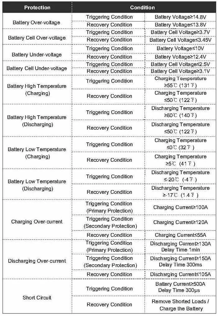
Battery Troubleshooting
If any problems occur during battery operation, please refer to the following instructions or contact the battery manufacturer for assistance:
- If the Activation Switch is plugged into the UP Communication Port of a battery in active mode, but the LED light on the Power Button does not become bright blue, the battery may have entered protection mode and is in need of special attention.
- When the battery voltage is too low to reliably power loads, please charge the battery as soon as possible.
- If the battery temperature is too high or too low, please cut off all connections and let the battery stand by until it cools down or warms up to room temperature.
Read all Instructions for Charging Battery User Manual
alliance RV Valor 2021 Battery Disconnect Switch User Manual
2021 alliance RV Valor Battery Disconnect Switch Instruction
Battery Disconnect Switch
Used to shut off all 12‐volt power that supplies RV. When the switch is activated the batteries are disconnected/isolated and no longer supply 12‐volt power to the RV. You will find the battery disconnect switch in the pass thru storage compartment of the 5th wheel and are typically mounted above docking station.
To operate the switch, simply turn the lever to the ON or OFF position. As shown below, a lanyard is attached to prevent the removable lever from being misplaced.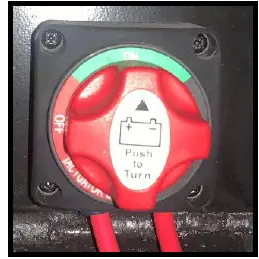
Solar Panels
Valor is equipped with roof mounted monocrystalline solar panels.
Cleaning and Maintenance
Solar panels generally require very little maintenance in order to function. The only thing they need is a periodic light cleaning to make sure dirt, leaves, and other debris aren’t obstructing the sun’s rays. To clean the panels use a soapy sponge and wipe dry with a squeegee.
Solar Charge Controller
Valor is equipped with a Rover 40 or 60 amp MPPT charge controller to give you the best charging efficiency for countless 12V off‐grid solar applications. Compatible with an assortment of batteries, including Lithium, the Rover Elite MPPT maximizes your solar charging energy through its smart tracking algorithm ensuring the most efficient to your battery. Additionally, the Rover Elite MPPT is equipped with multiple battery, controller, and solar protections giving you peace of mind and an optimized system you can trust.
40‐Amp Charge Controller (If So Equipped)
Parts Overview
- LCD Screen
- Operating Keys
- Mounting Holes
- RS485 Communication port
- PV Terminals
- Battery Terminals
- Remote Temperature Sensor Port
- Battery Voltage Sensor Port
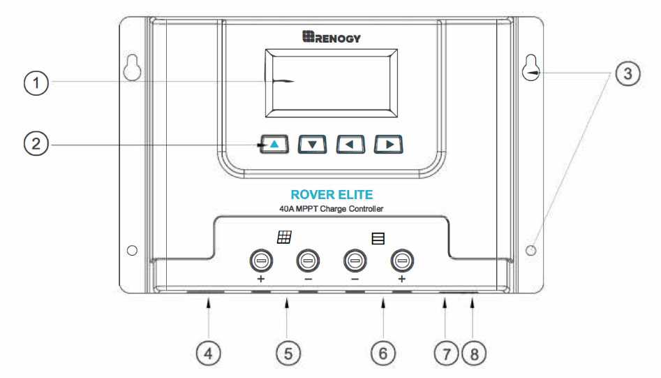
LCD Screen Indicators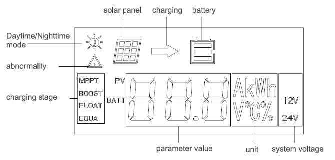
40‐Amp Charge Controller ‐ If So Equipped (Continued)
Operating Keys
Main Display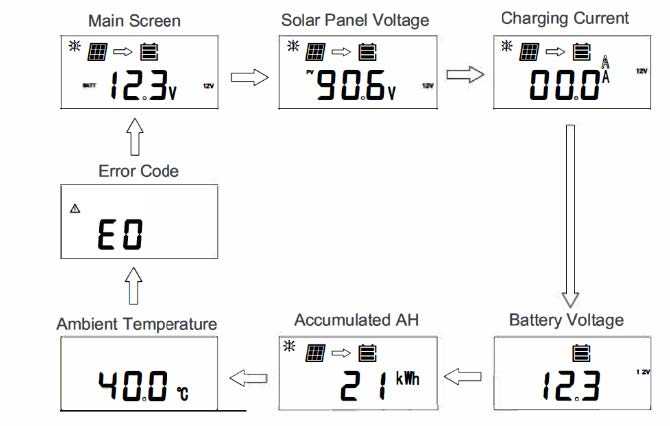
Note: The Error Code will not display unless there is an error. The menu will normally go from ambient temperature back to the main screen.
Error Codes/ Troubleshooting
If the Rover Elite is not functioning properly, it will display an error code not normally seen in the interface display. Depending on the code, you may attempt to troubleshoot the error to commence normal system operation.
Read all Instructions for Battery Disconnect Switch User Manual
alliance RV Valor 2021 Inverter – If So Equipped User Manual
alliance RV Valor 2021 Inverter – If So Equipped User Manual
Inverter
Inverter – If So Equipped
The Rangy PCL series inverter‐chargers combine an inverter and battery charger with an automatic transfer switch into one complete system. Featuring a 3‐stage battery charging mode when connected to utility AC power, the PCL series inverter‐charger can meet powerful demand needs as well as charge your battery bank. As a power supply, it is capable of producing cleaner, smoother, and more reliable electricity for a user’s electronic needs.
Inverter Parts Overview
Top View
- AC Input Cable Entry
- AC Output Cable Entry
- Wired Remote Control Cable Entry
- LCD Panel and Buttons
- Mounting Holes
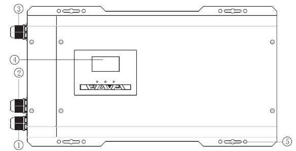
Left View
- Main ON/OFF Switch
- DC Negative Battery Terminal
- Battery Temperature Sensor Port
- RJ11 Port for connecting Wired Remote Control
- Rj45 Port for Future Development
- AC Output Terminal Block
- AC Input Terminal Block
- Main Power Switch Terminal Block
- Dry Contact Relay Port: NC, C, NO ports for connecting generators and making use of the Auto‐Gen Start feature.
- Inverter Output Protection Circuit Breaker
- Inverter Input Protection Circuit Breaker
- DC Positive Battery Terminal
- Fans that dissipate heat
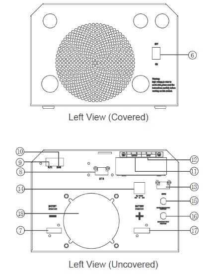 Automatic Transfer Relay
The PCL inverter chargers are equipped with a 30A transfer relay switch that switches between Inverter and Standby mode depending on the availability of AC input power. If AC is present, the transfer relay bypasses up to 30A of the incoming AC power through the inverter to power the AC loads on the inverter’s output. In the event AC power gets disconnected, the inverter will power the loads through the battery bank.
Auto Generator Start
The PCL inverter charger series have functions to automatically start and stop a generator for supplementing charge. The Auto Generator feature starts the Generator with the use of Normally Closed (NC) contacts of the relay that “opens” when the battery voltage drops to the programmed value of Program 96, Low Battery Voltage Set‐point. The Normally Open (NO) relay “closes”, and the auto generator starts commencing the generator to start charging the battery bank. When the battery is recharged and its voltage rises to the programmed value of Program 95, High Battery Voltage Set‐point The NC (closes) contacts and NO (opens) contacts of relay reset and the Generator will stop/shut down the Generator automatically. The PCL unit will then transfer back to “Inverting Mode”.
Note: While the generator is connected, the unit now operates in “Charging Mode” with the AC power from the Generator charging the batteries as well as providing power to the AC loads.
Read all Instructions for Inverter – If So Equipped User Manual
alliance RV Valor 2021 Starting the Generator User Manual
alliance RV Valor 2021 Starting the Generator User Manual
Starting the Generator
- Visually inspect for fuel and/or exhaust leaks. Do NOT start the generator until any fuel or exhaust leak is repaired.
- Position and hold the control switch to START until the generator starts. The status indicator on the switch flashes while cranking. It will stay on continuously when the generator set is running.
- If the generator fails to start, cranking will stop in approximately 30 seconds. The status indicator will blink, indicating an over crank fault. Wait 5 seconds for the control to reset before trying again. After 5 tries, let the starter motor cool down for 30 seconds before trying again.
- For top performance and engine life, especially in colder weather, let the engine warm up for 2 minutes before you put a load on the generator.
- Turn off your air conditioners and any other large appliances.
- Run the generator for 2 minutes to allow for cool down.
- Press the control switch into the STOP position.
The Load on the Generator
The power rating on the generator nameplate determines how much electrical load (motors, fans, heaters, air conditioners and other appliances) the generator can power. If the sum of the loads exceeds the generator set power rating, the generator will shut down or its line circuit breakers will trip.
To avoid shutdowns due to generator overload, use the electrical ratings from each appliance to compare the sum of the electrical load likely to be used at the same time to the generator rating. Appliance load and generator power are measured in terms of watts or kilowatts. 1 kilowatt = 1000 watts.
Typical Appliance Loads:
AVERAGE POWER REQUIRED
| APPLIANCE | WATTS | AMPS |
| Air Compressor (1hp) | 900 ‐ 1800 | 7.5 ‐ 15 |
| Air Conditioner | 1,200 ‐ 2,400 | 10 ‐ 20 |
| Battery Charger | Up to 3,000 | 6 ‐ 28 |
| Blender | 450 ‐ 700 | 3.3 ‐ 5.8 |
| Broiler | 1,400 ‐ 1,700 | 11.6 ‐ 14 |
| Vacuum | 1,000 ‐ 1,440 | 8.3 ‐ 12 |
| Stereo | 85 | .7 |
| Coffee Pot | 900 ‐ 1200 | 7.5 ‐ 10 |
| Computer | 60 ‐ 270 | .5 ‐ 2.25 |
| Laptop | 20 ‐ 50 | .16 ‐ .41 |
| Converter | 500 ‐ 1,000 | 4 ‐ 8 |
| Curling Iron | 20 ‐ 50 | .16 ‐ .41 |
| Dishwasher | 1,200 ‐ 2,400 | 10 ‐ 20 |
| Drill | 250 ‐ 1,000 | 2 ‐ 8 |
| Electric Blanket | 60 ‐ 100 | .5 ‐ .8 |
| Fan | 10 ‐ 175 | .08 ‐ 1.45 |
| Flat Iron | 40 ‐ 80 | .3 ‐ .6 |
| Electric Skillet | 1,000 ‐ 1,350 | 8 ‐ 11.25 |
| Game Console | 19 ‐ 200 | .16 ‐ 1.6 |
| Hair Dryer | 1,200 ‐ 1,875 | 10 ‐ 15.6 |
| Iron | 1,000 ‐ 1,800 | 8 ‐ 15 |
| Light Bulbs | 13 ‐ 100 | .1 ‐ .8 |
| Microwave | 750 ‐ 1,100 | 6.25 ‐ 9.2 |
Exercising your Generator
Your Generator should be exercised at least 2 hours a month if use is infrequent. Run your generator at approximately ½ rated power. A single 2‐hour exercise period is better than several shorter periods. This action helps drive off moisture, lubricates the engine, replaces stale fuel in fuel inlets and removes oxides from electrical contacts and generator slip rings. The result is better starting, longer engine life and greater reliability.
Resetting Line Circuit Breakers
If a generator set line circuit breaker or a circuit breaker in the power distribution panel trips, either a short has occurred or too many loads were connected.
If a circuit breaker trips, disconnect or turn off as many electrical loads as possible and reset the circuit breaker. If the circuit breaker trips right away, either the appliance (or electrical load) has a short or the circuit breaker is faulty. You should immediately schedule a service for repair. If the circuit breaker does not trip right away, reconnect loads one‐by‐one making sure not to overload the generator or cause a breaker to trip.
Read all Instructions for Starting the Generator User Manual
alliance RV Valor 2021 Televisions User Manual
alliance RV Valor 2021 Televisions User Manual
Televisions
The Valor is equipped with a 110‐volt smart TV in the main living area, and 12‐volt televisions in the bedroom and garage areas. Please refer to the specific TV manuals provided in the Alliance Owners Bag for operating instructions of these televisions.
Stereo
Your RV is equipped with a JBL AURA high-performance wall-mount media center.
Operation of your Stereo
Press Power button (1) on the front panel or remote control to power on your new JBL AURA system. Turn on your desired loudspeaker Zone(s) with A B or C buttons (3) on front panel or remote control. Zone A defaults on at power up.
FM Mode
- Press Source button (2) on front panel or FM (7) button on remote control
- Press and hold Next/Previous (6) to SEEK radio stations (Quick press for fine tuning)
- Preset Stations
- Tune to desired FM station. Press and hold Play button (5) to enter into Preset mode. Press Next/Previous (6) to display desired preset location.
- Press Play button (5) to save current station.
- To recall presets, press Play button (5) to toggle through presets 01‐10
Operation of Your Stereo (Continued)
BT Mode
- Press the Source button (2) on the front panel or BT (8) button on remote control.
- Press the Pairing button (4) to connect your Bluetooth® compatible audio device. Follow pairing instructions on your device.
- Navigate your selections with the Next/Previous (6) buttons.
- Play/Pause selections with Play button (5).
MiZONE (Play your Bluetooth device outside while watching TV inside)
- Play your currently paired Bluetooth® audio device in either Zone B or C independent of Zone A.
- Hold for more than 2 seconds and release Zone B or C button (3).
- Use your device’s controls for volume level and content selection.
AURA Ring
- Press the Light Effect button (10) repeatedly to change the visualization AURA ring (9). The light ring can be selected between 3 modes: MOOD (slow and soft rotation of color, NEUTRAL (soft white color to match illumination), and PULSE (slow rotation of color pulsing to the beat of the music).
MONITOR PANEL
This system allows monitoring of fresh water, gray water, black water and battery levels. All functions are controlled from computer grade tact switches for easy operation. Power control of the water heater, water pump, tank heaters, some of the RVs lights, awnings and slideouts are also done from the central monitor panel shown below.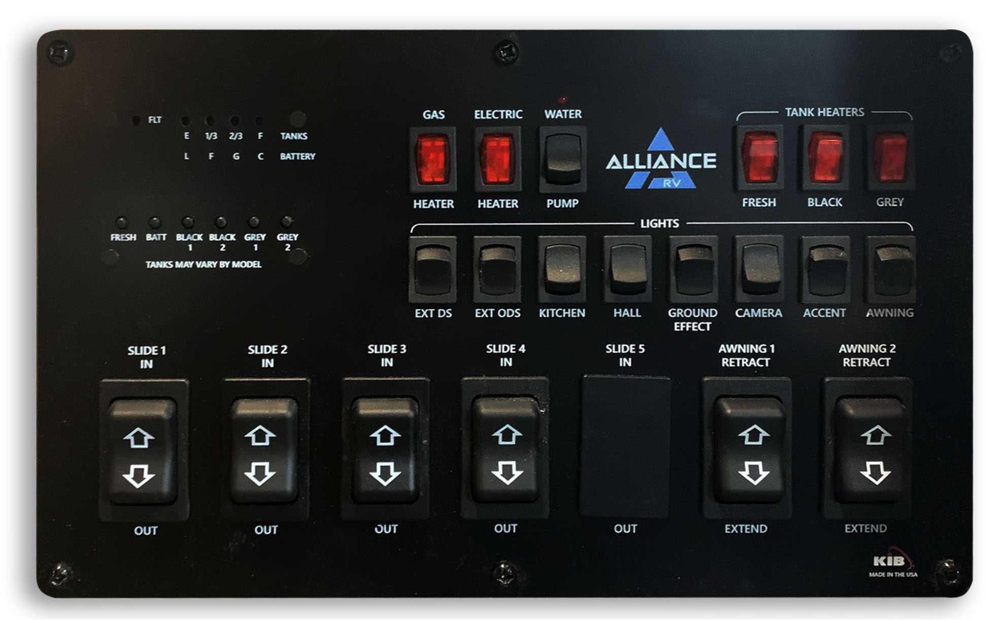
AWNINGS
Your Alliance RV comes standard with a power awning and in some cases, depending on the floor plan, may have two power awnings installed from the factory.
Awning Operation
Extending the Awning
- First, verify that the battery is fully charged and connected to the electrical system.
- Press and hold the awning extend button in the monitor panel.
- NOTE: Extension is considered complete when the fabric is completely unrolled, the valance sean is visible and a section of the awning tube is exposed.

- NOTE: The fabric should always be above the tube. However, if the extend switch is engaged too long or it is accidentally hit, the awning will roll up backward. To correct the orientation of the fabric, press the retract button to extend it to its correct position and normal operation can resume.
- NOTE: Tying down the roller tube once the awing is extended will not all the free-floating support arms to work as designed and can cause damage to the awning or RV.
Read all Instructions for Televisions User Manual
alliance RV Valor 2021 Awning Component Breakdown User Manual
alliance RV Valor 2021 Awning Component Breakdown User Manual
Awning Component Breakdown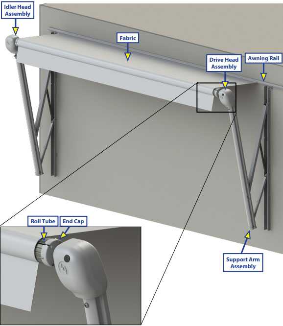
Power Rear Awning
The Power Rear Awning switch is located in the garage area. It is very important to keep the awning clean. Maintaining your awning in good condition can prevent costly repairs.
- RETRACT the awning to the travel position during windy or stormy weather conditions, or if you will be away from the RV for an extended period of time.
For more information, please refer to the awning manufacturer’s user manual.
HEATING, COOLING & VENTILATION
Air Conditioning
Alliance RV main living quarters (downstairs) will utilize two “direct cool” Coleman air conditioners. These units are mounted on the exterior roof of the RV with a combination shroud mounted on the inside ceiling of the RV. We’ve opted for most of the RV to be cooled with these direct cool units as they are significantly more efficient than your typical ducted system. The front/upper deck of the RV will utilize a ducted air conditioner system. Due to the nature of the design in the front/upper deck containing multiple rooms and areas that can be isolated with doors, a ducted system is utilized. Each air conditioner will be operated by its own individual thermostat.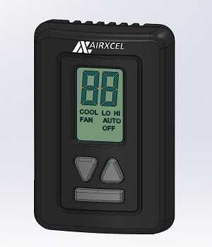
Furnace
This couch is heated with an SF‐Q series Suburban furnace that provides 42,000 BTU’s. An exterior access door allows for ease of service. The furnace is operated with the Airxcel thermostat that is tied to the main air conditioner unit. The main air conditioner unit is the control that operates the central air conditioner in the RV.
Operating the Furnace
WARNING
DO NOT OPERATE THE FURNACE WHILE VEHICLE IS IN MOTION OR BEING TOWED
NOTE: During initial firing of this furnace, a burn‐off of excess paint and oils remaining from manufacturing process may cause “smoking” for 5 – 10 minutes.
- Stop! Read the furnace user’s manual supplied with the furnace.
- Turn the manual valve (if equipped) or the valve at the outside propane tank to the
“OFF” position. Do not force - Set the thermostat above room temperature to begin blower operation. A slight delay will occur before the blower comes on. Allow blower to run for 5 minutes for combustion chamber purge cycle. If blower does not come on or stops before ignition cycle, go to shut down and contact your dealer.
- After 5 minutes, move thermostat lever below room temperature. Blower will remain on. Wait approximately 2 minutes for blower to go off.
- Open manual shut‐off valve (if equipped) or the valve at the outside propane tank. Correct operating characteristics depend on the valve being positioned fully open. Never attempt to operate with a valve partially closed. NOTE: This furnace is equipped with a valve shut‐off switch. If the furnace is started with shut‐off switch in “OFF” position, the furnace motor will run for 30 seconds, then shut off. During this sequence no gas will flow to the burner and the furnace will lock out requiring the user to cycle either the thermostat or unit power to reset the furnace. Ensure the shut‐off switch is in the “ON” position for proper operation.
- Set the thermostat to desired setting. If set above room temperature, blower will come on.
- Allow 30 seconds for main burner to light after blower comes on. This furnace is equipped with an ignition device which automatically lights the burner. Do Not try to light the burner by hand.
- If the burner does not light, repeat steps 1 thru 8.
- If after three 3 attempts with no ignition, go to shut down and contact your dealer. Do not continue to cycle the furnace. NOTE: If the furnace locks out, the blower will go off in 5 minutes and remain off until it is reset by reactivating the thermostat.
To Turn the Furnace Off
- Set the thermostat to lowest setting, then turn the thermostat to the “OFF” position.
- Turn the manual shut off valve (if equipped) to the “OFF” position.
Thermostat
The display indicates the mode and the room temperature. When the mode button is pressed once, the thermostat will wake. When the mode button is pressed again, the mode will change. Press the up or down button to wake the thermostat, the set temperature will display, and the mode will flash. Press the up or down button again to change the set temperature. The thermostat will go back to sleep after 5 seconds of no activity.
Read all Instructions for Awning Component Breakdown User Manual
alliance RV Valor 2021 Fireplace User Manual
alliance RV Valor 2021 Fireplace User Manual
Fireplace
Remote Control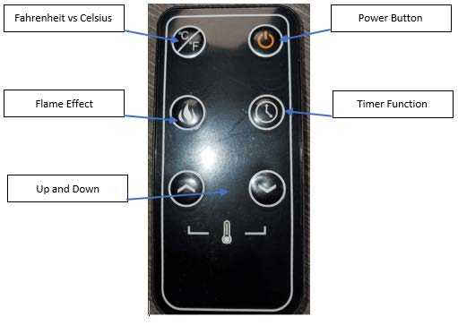
- Fahrenheit Vs. Celsius – Press this button to toggle between the two temperature scales.
- Flame Effect ‐ Press this button to change the flame effect. The unit will beep. Press again to decrease the flame intensity. There are 6 light settings for your selection. The flame optics will go lower under the sequence of 6,5,4,3,2,1. Pressing the button again will stop the flame effect.
- Up and Down – Press these buttons to set the desired temperature.
- Power Button – Turn the unit on and off with this button.
- Time Function – Press this button for the timer function. The letters “0H” to “8H” will appear on the LED screen. “OH” means there is no set running time and the heater will run continuously. The letters “1H” thru “8H” means the number of hours that the heater will operate before shutting off.
NOTE: The battery in the remote is a CR2025 battery.
Ventilation
MAXXAIR fans are located in the kitchen and master bathroom areas. These high‐powered fans are an industry staple that operates very easily. These fans are crucial in your RVs ventilation and assist with minimizing condensation, especially in extended use and extreme temperature situations. Your MAXXAIR fans will be controlled by remote wall-mounted controls. There is a manual override for opening and closing of the lid on the unit at the ceiling.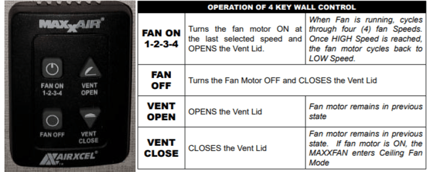
Range Hood
The microwave situated above your stove has a built‐in fan. This will be covered in the Appliances section to follow.
APPLIANCES
12‐Volt Refrigerator
This unit is equipped with a French door refrigerator that is operated by 12‐volt power supplied by your RV’s batteries.
WARNING
- STORAGE OF FLAMMABLE MATERIALS BEHIND OR AROUND THE REFRIGERATOR CREATES A FIRE HAZARD. DO NOT USE THE AREA BEHIND THE REFRIGERATOR TO STORE ANYTHING, ESPECIALLY FLAMMABLE MATERIALS
- INCORRECT ADJUSTMENT, CHANGE OR MAINTENANCE OF THIS REFRIGERATOR CAN CAUSE PERSONAL INJURY OR DEATH. ALWAYS USE AN AUTHORIZED TECHNICIAN FOR NEEDED WORK
WARNING
- FAILURE TO READ AND UNDERSTAND THE USER’S MANUAL AND ALL IT’S WARNINGS AND CAUTIONS COULD RESULT IN PROPERTY DAMAGE, DEATH OR SERIOUS INJURY
Operating the 12‐Volt Refrigerator
Electronic Display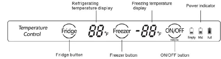
- “Fridge” Button: Push to adjust the set temperature of refrigerating room
- “Freeze” Button: Push to adjust the set temperature of the freezing room
- “ON/OFF” Button: Press and hold the ON/OFF button for 3 seconds to enter a shutdown or power‐on state.
Operating the 12‐Volt Refrigerator (Continued)
Setting the Refrigerating Room
The LED display turns bright when the door is open. Push the “Fridge” button. The buzzer rings. Then the refrigerating room turns into the setting condition. The temperature pattern turns flash and the temperature of the refrigerating room increases 1. The temperature will recycle as “01”—“02” —“03”—“04”—“05”—“06”—“07”— “——”—“01”. When the temperature turns “07”, push the “Fridge” button, then the refrigerator turns into the condition of pre‐closing the refrigerating room and the LED display turns “——” with a flashing light.
Read all Instructions for Fireplace User Manual
alliance RV Valor 2021 Microwave User Manual
alliance RV Valor 2021 Microwave User Manual
Microwave
Your OTR (Over‐the‐Range) microwave is equipped with a vent fan and a light underneath the microwave. The fan works as a range hood to filter out smoke and other odors from cooking. Use your range hood anytime you cook, this will help maintain the air quality in your RV. Be sure to read your microwave user’s manual for additional information.
Range/Cooktop
Your gas range represents the newest RV range design and is designed for reliable and trouble‐free performance.
Before Using Your Range
Remove all packaging materials and wipe the surfaces of your range with a damp cloth or sponge. When you turn on a burner or the oven for the first time, smoke and odors may be present. This is normal, make sure the room is well-ventilated.
WARNING
DO NOT STORE OR USE GASOLINE OR OTHER FLAMMABLE VAPORS AND LIQUIDS IN THE VICINITY OF THIS OR ANY OTHER APPLIANCE.
WARNING
IF YOU SMELL GAS:
- EXTINGUISH ANY OPEN FLAME
- DO NOT TRY TO LIGHT ANY APPLIANCE
- DO NOT TOUCH ANY ELECTRICAL SWITCH
- IMMEDIATELY CALL YOUR LOCAL EMERGENCY SERVICES
WARNING
READ ALL INSTRUCTIONS IN THE RANGE OWNER’S MANUAL BEFORE USING THIS APPLIANCE NEVER USE THE RANGE AS A SOURCE OF HEAT.
Control Panel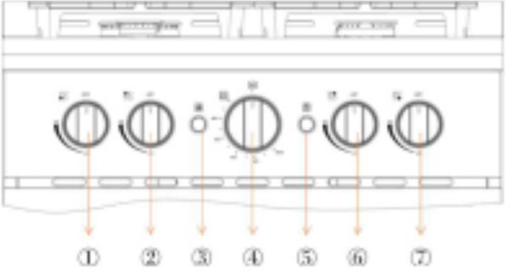
- Front Left Burner Control Knob
- Rear Left Burner Control Knob
- Convection ON/OFF Knob
- Oven Temperature Control Knob
- Oven Light ON/OF Knob
- Front Right Burner Control Knob
- Rear Right Burner Control Knob
Using Your Gas Range
- Using proper flame size: adjust the flame so it does not extend beyond the edge of utensils. Undersized utensils will expose a portion of the burner flame to direct contact and may result in the ignition of clothes. Proper utensil and flame size will improve efficiency. Burners are different sizes for different utensil sizes. The furniture above hobs has the potential risk during gas range working.
- If you use a stovetop grill on a sealed gas burner, it will cause incomplete combustion and can result in carbon monoxide poisoning.
- Know which knob controls each surface burner. Place a pan of food on the burner before turning it on, and turn the burner off before removing the pan.
- Always turn the knob to the full HI position when igniting top burners and visually check that burner is lit.
- Then adjust the flame so it does not extend beyond the edge of the utensil.
- Utensil handles should be turned outward and not extend over adjacent surface burners. This will help reduce the risk of burns, ignition of flammable materials, and spillage due to unintentional contact with the utensil.
- Never leave surface burners unattended at high heat settings: Boilovers cause smoking and greasy spillovers that may ignite.
How to Use the Top Burners
Gas flow to the burners is adjusted by turning the knobs that control the valves. Turning the knob so that the indicator line points to the symbols printed on the panel achieves the following functions: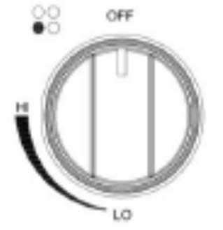
- When the knob is rotated to the maximum position it will permit the rapid boiling of liquids, whereas the minimum position allows the simmering warming of food or maintaining boiling conditions of liquids.
- To reduce the gas flow to a minimum, rotate the knob further counter‐clockwise to point to the LO position.
- Other intermediate operating adjustments can be achieved by positioning the indicator between the HI and Lo positions, and never between the HI and OFF positions.
- When the range is not being used, set the gas knobs to their OFF positions and also close the gas shut‐off valve placed on the main gas supply line.
Lighting Gas Burners
In order to light the burner, you must:
- Push and turn the knob in a counterclockwise direction up to the HI position (maximum rate), push in and hold the knob until the flame has been lit. The sparks produced by the internal igniter will light the designated burner.
Note: In the event that the local gas supply conditions make it difficult to light the burner in the HI position, try again with the knob in Lo position. - Adjust the gas valve to the desired position.
Note: To re‐light, the burner, return the knob to the OFF position and repeat the operations for lighting.
Read all Instructions for Microwave User Manual
alliance RV Valor 2021 Troubleshooting User Manual
alliance RV Valor 2021 Troubleshooting User Manual
Troubleshooting
| PROBLEM/SYMPTOM | POSSIBLE CAUSE/SOLUTION |
|
Area surface burners will not ignite or area surface burners do not ignite uniformly. |
Surface control knob has not been fully rotated to the
HI position. |
| Check to see if gas valve is open. If not,open it. | |
| Burners are clogged. Make sure burner is off. Use a
small wire, toothbrush or needle to clean burner portsandslots. |
|
| Low gas level in tank. Refill or replace gastank. | |
| There is moisture on the burner. With burner off, dry
burner throughly. |
|
|
Surface burner flame is yellow or orange instead of blue. |
Debris may be present in gas line. Let burner run for a
few minutes to see if flame changes to blue. |
| Humid air in the home, sometimes caused by running a
humidifier may cause flames to be burn yellow. |
Centralized Docking Station
Alliance RV uses the Nautilus P4 Water Management System. With this system you’ll have the ability to perform the following functions from a centralized and easy-to-access location:
- The power fills your fresh water tank for dry camping.
- Use your pump to supply water to fixtures from the fresh water tank
- Use your pump to siphon fill or sanitize your fresh water tank from a bucket
- Connect to city water at the camping site to supply water to fixtures
- Winterize your plumbing lines and fixtures
- Bypass hot water heater when winterizing to avoid water heater damage
- Rinse the black tank to help control odors and prevent sewage buildup
- Rinse off items outside the unit with a hot/cold faucet
- Connect up to three (3) coax lines with satellite, cable and auxiliary
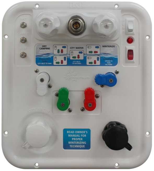
Docking Station Handle Position and Valve Routing
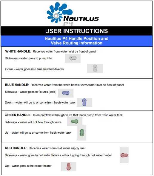
Filling the Fresh Water Tank – Power Fill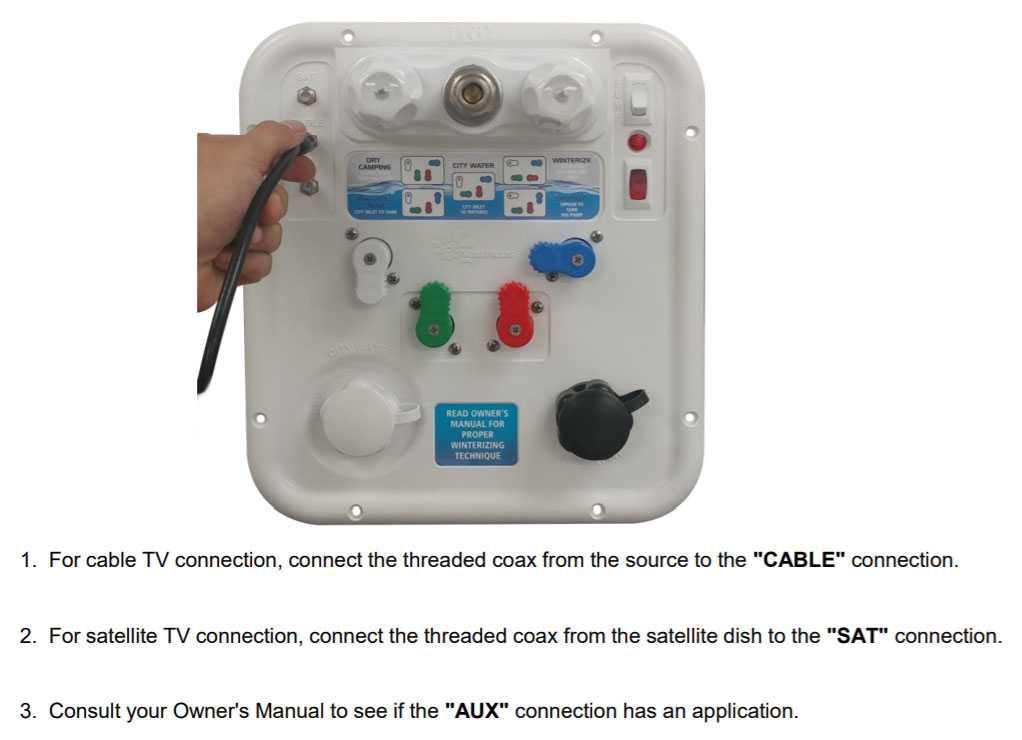
Fill and/or Sanitize the Fresh Water Tank with the Pump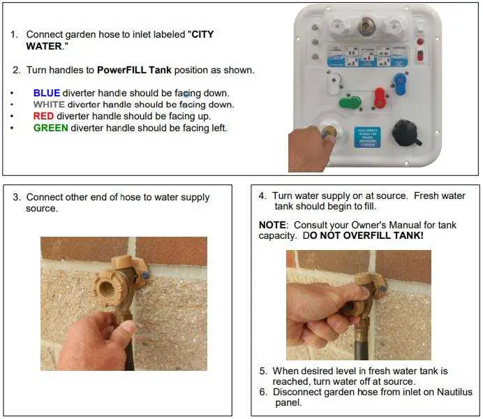
NOTE: For sanitizing, a solution of 1 gallon of water and one-quarter cup of household bleach should be prepared for every fifteen gallons of holding tank capacity.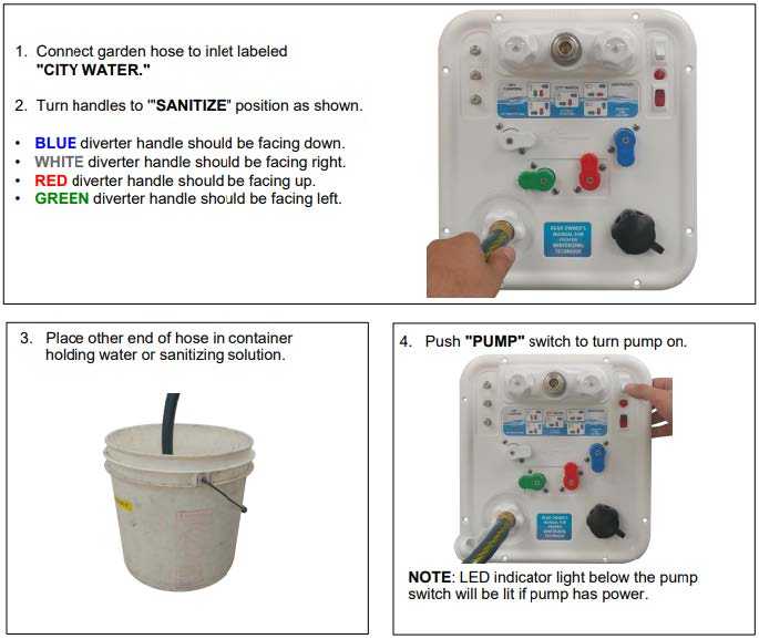
Read all Instructions for Troubleshooting User Manual
alliance RV Valor 2021 Waste Water User Manual
2021 alliance RV Valor Waste Water User Manual
Waste Water System
The waste system contains holding tanks. The quantity of tanks along with the location is dictated by the floor plan of the RV. All tanks are equipped with electric heating pads that can be controlled in the monitor panel.
- Black tanks hold toilet waste. There are some things to note with black tanks. Black tanks typically will need a digester/deodorant (talk with your RV dealer for recommendations). Black tanks require RV toilet paper. RV toilet paper breaks down quicker and is specifically designed for this type of waste water system. You’ll find that this toilet paper breaks down more quickly and allows the waste water to flow more easily during the dumping process. A black tanks monitoring electronics can be adversely affected by debris handing up on the reading probes. For this case, we have installed a tank flush for your black tank(s) to assist in keeping the probe indicators clean so that you have accurate readings on the tank’s levels.
- Gray tanks, an integral part of the waste water system. Gray tanks hold your sink and shower waste water. Gray tanks require less maintenance due to the difference in waste produce making its way into the tank. It may be ideal to dump black tanks first and then your gray tanks, the gray tank running thru the main dump will help in keep the pipeline cleaner.
Toilet
Alliance RV uses the best-in-class 310 series Dome tic RV toilet. Each toilet is 100% factory tested to assure watertight seal in the toilet bowl before it even leaves Docetic. After installation by Alliance RV, the entire waste system is flood tested for leaks by filling the system with water to the rim of the bowl. To use the toilet, first add water to the toilet by pressing the flush pedal only partially down. Water will flow into the bowl while the flush ball remains closed. If the flush ball moves, let up
Toilet slightly on the pedal until the ball closes. Adding water to the empty bowl acts as a trap and helps prevent holding tank odors from entering the RV. Adding water is always recommended prior to flushing solids and/or toilet paper.
To flush the toilet, press the pedal down until it contacts the floor. Release the pedal after the flush is complete. When flushing liquids, quick press of the pedal for 1 to 2 seconds will do. When flushing solids, the pedal should be pressed until the contents are rinsed from the bowl. Never flush longer than needed as this will cause the holding tank capacity to be used up and require more frequent black tank dumps. A small amount of water should collect in the bowl after a flush, this will create an airtight seal. Further instructions and information can be found in the toilet owners’/users manuals.
Dumping Your Waste Tanks
Your RV is equipped with cable termination valves. Most of these valves are going to be routed to the centralized docking station convenience center for ease of pulling. However, in some occasions, dictated by floor plan, you may find a gate valve pull handles located on the off‐door side frame rail of the RV.
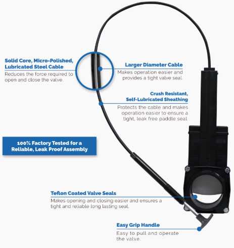 Monitoring Your Water Systems
This panel monitors the fill levels of the fresh water, grey water and black water tanks. You will also operate the heaters on the holding tanks here and as well as the power to the fresh water pump (you’ll also find a water pump switch in the exterior docking station) and the water heater. These switches will illuminate while in the on position.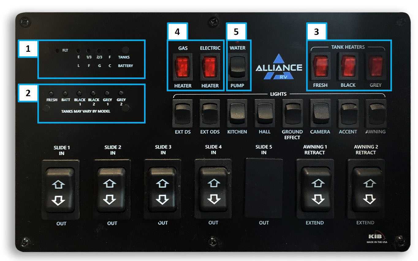
When an individual button is pressed (box 2), the lights above the switch (box 1) illuminate to reveal the level of the selection pushed. For the battery level indicator, the individual letters mean the following:
- L = Low at 6.0 volts
- F = Fair at 11.6 volts
- G = Good at 12.1 volts
- C = Charge at 12.7 volts
The water pump is operated with the water pump switch (box 4) as well as the gas and electric options for the water heater (box 5). The gas water heater switch enables propane operation of the water heater while the electric switch enables electric operation of the water heater. Both switches being on will allow for a quicker hot water recovery. The water heater can be operated in electric or gas only by turning one of the individual switches on.
Note: The holding tank heaters will also be operated from the monitor panel (box 3).
Washer / Dryer Prep
The washer/dryer prep is located in the front closet or garage of the 5th wheel. You will find both hot and cold water connection points. Should a washer and dryer be your desire, please consult with your dealership or Alliance RV for our installation recommendations. Otherwise, you will find functional cabinet space in that area.
FAQ
Alliance RV is noted for its build quality–both in terms of the materials the company uses and the verification of its craftsmanship through rigorous testing. The manufacturer uses Azdel for its exterior panels, which many consider to be superior to Luan plywood seen in other RVs.
Every Alliance RV is generously backed with a 3-year limited structural and 1-year limited base warranty. Further, what really makes Alliance RV stand out is our willingness to communicate our guiding principle of “Do The Right Thing”.
For some, the choice is simple: life on the road in an RV is a nonstop adventure with fringe benefits like more leisure time with loved ones, a simpler life, and financial flexibility. It’s no wonder the idea appeals to so many, particularly as modern life gets crazier and new model RVs get cozier
The Brady brothers knew their soon-to-be competitors were missing something that the industry sorely needed: human connections, with dealers and consumers alike. So in 2019, the Bradys launched Alliance RV, a towable RV manufacturer.
RVs require a lot of upkeep. You need to keep on top of cleaning, which includes dumping RV waste. You also need to make sure fluids are topped up and tired are inflated. Then of course, there could be occasional repairs that need doing
If you have a family, off-road toys with gear, and the desire to explore the great outdoors then you need an Alliance RV Valor fifth wheel toy hauler! They are packed with quality equipment that is adventure-ready for even the extreme journeys with performance running gear and the coolest HVAC system on the market.
The RV Industry Association from time to time profiles its members and in this installment, features Coley Brady, who co-founded Alliance RV with his brother, Ryan .
The company was co-founded in May of 2019 by brothers Ryan and Coley Brady. The brothers brought 30+ years of experience in the RV industry to Alliance RV from their positions in senior leadership at Heartland RV as well as other manufacturers.
RV living is exactly what you think it is—you live in a recreational vehicle (or RV) that allows you to move around and live in different places. It’s the perfect living situation for anyone who wants to travel, gain new experiences, and not be tied down by a permanent residence.
Useful Link
alliance RV Avenue 2021 User Manual
alliance RV paradigm 2021 User Manual