
Dodge Challenger 2022 Introduction User Manual
Introduction
Dear Customer,
Congratulations on the purchase of your new Dodge vehicle. Be assured that it represents precision workmanship, distinctive styling, and high quality. This Owner’s Manual has been prepared with the assistance of service and engineering specialists to acquaint you with the operation and maintenance of your vehicle. It is supplemented by customer-oriented documents. Within this information, you will find a description of the services that FCA US LLC offers to its customers as well as the details of the terms and conditions for maintaining its validity. Please take the time to read all of these publications carefully before driving your vehicle for the first time. Following the instructions, recommendations, tips, and important warnings in this manual will help ensure safe and enjoyable operation of your vehicle. This Owner’s Manual describes all versions of this vehicle. Options and equipment dedicated to specific markets or versions are not expressly indicated in the text. Therefore, you should only consider the information that is related to the trim level, engine, and version that you have purchased. Any content introduced throughout the Owner’s Information, which may or may not be applicable to your vehicle, will be identified with the wording “If Equipped”. All data contained in this publication are intended to help you use your vehicle in the best possible way. FCA US LLC aims at a constant improvement of the vehicles produced. For this reason, it reserves the right to make changes to the model described for technical and/or commercial reasons. For further information, contact an authorized dealer. When it comes to service, remember that authorized dealers know your Dodge best, have factory-trained technicians, genuine Mopar® parts, and care about your satisfaction.
SYMBOLS KEY
WARNING
These statements are against operating procedures that could result in a collision, bodily injury and/or death.
CAUTION
These statements are against procedures that could result in damage to your vehicle.
NOTE
A suggestion which will improve installation, operation, and reliability. If not followed, may result in damage.
TIP
General ideas/solutions/suggestions on easier use of the product or functionality.
 PAGE REFERENCE ARROW
Follow this reference for additional information on a particular feature.
 FOOTNOTE
If you do not read this entire Owner’s Manual, you may miss important information. Observe all Cautions and Warnings.
VEHICLE MODIFICATIONS/ALTERATIONS
WARNING
Any modifications or alterations to this vehicle could seriously affect its roadworthiness and safety and may lead to a collision resulting in serious injury or death.
WARNING
To prevent SERIOUS INJURY or DEATH when using “Track-Use” parts and
equipment:
- NEVER use any “Track-Use” equipment on public roads. FCA US LLC does
not authorize the use of “Track-Use” equipment on public roads. - The intended use of “Track-Use” parts is for race vehicles on race tracks. To help ensure the safety of the race driver, engineers should supervise
the installation of “Track-Use” parts. - FCA US LLC does not authorize the installation or use of any part noted as “Track-Use” on any new vehicle prior to its first retail sale.
WARNING
To prevent SERIOUS INJURY or DEATH:
- ALWAYS remove any “Track-Use” equipment before driving on public roads.
- ALWAYS properly use your three-point seat belts when driving on public roads.
- In a collision, you and your passengers can suffer much greater injuries if
- you are not properly buckled up. You can strike the interior of your vehicle or other passengers, or you can be thrown out of the vehicle.
SYMBOL GLOSSARY
Some car components have colored labels with symbols indicating precautions to be observed when using this component. It is important to follow all warnings when operating your vehicle. See below for the definition of each symbol Ú page 73.
NOTE
Warning and Indicator lights are different based upon equipment options and current vehicle status. Some telltales are optional and may not appear.
Red Warning Lights
| Red Warning Lights | |
|
|
Air Bag Warning Light |
|
|
Brake Warning Light |


| Red Warning Lights | |
|
|
Battery Charge Warning Light |
|
|
Door Open Warning Light |
|
|
Oil Pressure Warning Light |
|
|
Oil Temperature Warning Light |
|
|
Seat Belt Reminder Warning Light |
|
|
Electronic Throttle Control (ETC) Warning Light |
|
|
Engine Coolant Temperature Warning Light |
|
|
Transmission Temperature Warning Light |


| Red Warning Lights | |
|
|
Electric Power Steering (EPS) Fault Warning Light |
|
|
Trunk Open Warning Light |
|
|
Vehicle Security Warning Light |


| Yellow Warning Lights | |
|
|
Engine Check/Malfunction Indicator Warning Light (MIL) |
|
|
Electronic Stability Control (ESC) Active Warning Light |
|
|
Electronic Stability Control (ESC) OFF Warning Light |
| Yellow Warning Lights | |
|
|
Tire Pressure Monitoring System (TPMS) Warning Light |
|
|
Anti-Lock Brake System (ABS) Warning Light |
|
|
Low Fuel Warning Light |
|
|
Service Forward Collision Warning (FCW) Light |
|
|
Loose Fuel Filler Cap Warning Light |
|
|
Service AWD Warning Light |
|
|
Service Adaptive Cruise Control Warning Light |


| Yellow Indicator Lights | |
|
|
Forward Collision Warning OFF Indicator Light |
| Green Indicator Lights | |
|
|
Adaptive Cruise Control (ACC) Set Without Target Vehicle Light |
|
|
Adaptive Cruise Control (ACC) Set With Target Vehicle Light |
|
|
Parking/Headlights On Indicator Light |
|
|
Front Fog Indicator Light |
|
|
Turn Signal Indicator Lights |
|
|
ECO Mode Indicator Light |


| Green Indicator Lights | |
|
|
Cruise Control Set Indicator Light |
|
|
Sport Mode Indicator Light |

| White Indicator Lights | |
|
|
Cruise Control Ready Indicator |
|
|
Adaptive Cruise Control (ACC) Ready Light |
| Blue Indicator Lights | |
|
|
High Beam Indicator Light |

GETTING TO KNOW YOUR VEHICLE
KEYS
KEY FOB
Your vehicle is equipped with a key fob which supports Passive Entry, Remote Keyless Entry (RKE), Keyless Enter ‘n Go™ (if equipped), Remote Start (if equipped), and remote trunk operation. The key fob allows you to lock or unlock the doors and trunk from distances up to approximately 66 ft (20 m). The key fob does not need to be pointed at the vehicle to activate the system. The key fob also contains an emergency key, which is stored in the rear of the key fob.
NOTE
- The key fob’s wireless signal may be blocked if the key fob is located next to a mobile phone, laptop, or other electronic device. This may result in poor performance.
- With ignition in the ON position and the vehicle moving at 2 mph (4 km/h), all RKE commands are disabled.
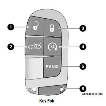
Key Fob
- Unlock
- Trunk Open
- Lock
- Remote Start (If Equipped)
- PANIC Button
- Emergency Key
NOTE
In case the ignition switch does not change with the push of a button, the key fob may have a low or fully depleted battery. A low key fob battery can be verified by referring to the instrument cluster, which will display directions to follow Ú page 322.
To Lock/Unlock The Doors And Trunk
Push and release the unlock button on the key fob once to unlock the driver’s door or twice within five seconds to unlock all doors. Push and release the lock button on the key fob to lock all doors. When the doors are unlocked, the turn signals will flash and the illuminated entry system will be activated. When the doors are locked, the turn signals will flash and the horn will chirp. This setting can be adjusted in the Uconnect system page 123.
NOTE
- If the vehicle is unlocked with the key fob, and no door is opened within 60 seconds, the vehicle will relock and the Vehicle Security system (if equipped) will arm.
- If one or more doors are open, or the trunk is open, the doors will lock. The doors will unlock again automatically if the key is left inside the passenger compartment, otherwise the doors will stay locked.
All doors can be programmed to unlock on the first push of the unlock button through Uconnect Settings Ú page 123.
NOTE
When you use the key fob to open any door, the courtesy lights, overhead lights, and approach lighting in the outside mirrors (if equipped) will turn on.
Key Left Vehicle Feature
If a valid key fob is no longer detected inside the vehicle while the vehicle’s ignition system is in the ON/RUN or START position, the message “Key Left Vehicle” will be shown in the instrument cluster display along with an interior chime. An exterior audible and visual alert will also be activated to warn the driver.
The vehicle’s horn will rapidly chirp three times along with a single flash of the vehicle’s exterior lights.
NOTE
The vehicle’s horn will rapidly chirp three times along with a single flash of the vehicle’s exterior lights.
NOTE
To Unlatch The Trunk
Push the trunk button on the key fob two times within five seconds to unlatch the trunk.
Replacing The Battery In The Key Fob
The recommended replacement battery is one CR2032 battery.
NOTE
- Customers are recommended to use a battery obtained from Mopar®. Aftermarket coin battery dimensions may not meet the original OEM coin battery dimensions.
- Perchlorate Material — special handling may apply. See www.dtsc.ca.gov/hazard-ouswaste/perchlorate for further information.
- Do not touch the battery terminals that are on the back housing or the printed circuit board.
- Remove the emergency key (2) by sliding the emergency key release (1) on the back of the key fob and pulling the emergency key out with your other hand.
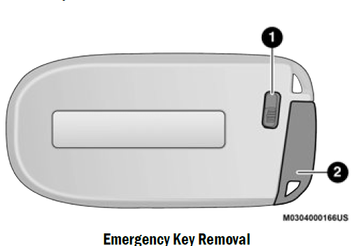
- Emergency Key Release Button
- Emergency Key
- Separate the key fob halves using a #2 flat blade screwdriver or a coin, and gently pry the two halves of the key fob apart. Make sure not to damage the seal during removal.
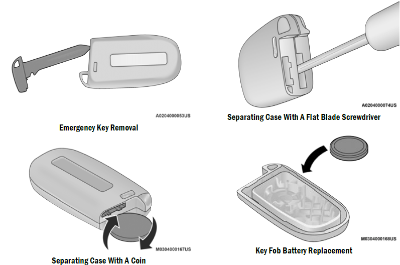
NOTE
Separating the case can also be done with a flat head screwdriver. - Remove the back cover to access and replace the battery. When replacing the battery, match the (+) sign on the battery to the (+) sign on the inside of the battery clip, located on the back cover. Avoid touching the new battery with your fingers. Skin oils may cause battery deterio-ration. If you touch a battery, clean it with rubbing alcohol.
- To assemble the key fob case, snap the two halves together.
WARNING
- The integrated key fob contains a coin cell battery. Do not ingest the battery; there is a chemical burn hazard. If the coin cell battery is swallowed, it can cause severe internal burns in just two hours and can lead to death.
- If you think a battery may have been swallowed or placed inside any part of the body, seek immediate medical attention.
- Keep new and used batteries away from children. If the battery compartment does not close securely, stop using the product and keep it away from children.
Programming And Requesting Additional Key Fobs
Programming the key fob may be performed by an authorized dealer.
NOTE
- Once a key fob is programmed to a vehicle, it cannot be repurposed and reprogrammed to another vehicle.
- Only key fobs that are programmed to the vehicle electronics can be used to start and operate the vehicle. Once a key fob is programmed to a vehicle, it cannot be programmed to any other vehicle.
WARNING
- Always remove the key fobs from the vehicle and lock all doors when leaving the vehicle unattended.
- For vehicles equipped with Keyless Enter ‘n Go™ Ignition, always remember to place the ignition in the OFF position.
Duplication of key fobs may be performed at an authorized dealer. This procedure consists of programming a blank key fob to the vehicle electronics. A blank key fob is one that has never been programmed.
NOTE
- When having the Sentry Key Immobilizer system serviced, bring all vehicle keys with you to an authorized dealer.
- Keys must be ordered to the correct key cut to match the vehicle locks.
SENTRY KEY
The Sentry Key Immobilizer system prevents unauthorized vehicle operation by disabling the engine. The system does not need to be armed or activated. Operation is automatic, regardless of whether the vehicle is locked or unlocked. The system uses a key fob, keyless push button ignition and a Radio Frequency (RF) receiver to prevent unauthorized vehicle operation. Therefore, only key fobs that are programmed to the vehicle can be used to start and operate the vehicle. The system cannot reprogram a key fob obtained from another vehicle. After placing the ignition in the ON/RUN position, the Vehicle Security Light will turn on for three seconds for a bulb check. If the light remains on after the bulb check, it indicates that there is a problem with the electronics. In addition, if the light begins to flash after the bulb check, it indicates that someone attempted to start the engine with an invalid key fob. In the event that a valid key fob is used to start the engine but there is an issue with the vehicle electronics, the engine will start and shut off after two seconds.
If the Vehicle Security Light turns on during normal vehicle operation (vehicle running for longer than 10 seconds), it indicates that there is a fault in the electronics. Should this occur, have the vehicle serviced as soon as possible by an authorized dealer.
CAUTION
The Sentry Key Immobilizer system is not compatible with some aftermarket Remote Start systems. Use of these systems may result in vehicle starting problems and loss of security protection.
All of the key fobs provided with your new vehicle have been programmed to the vehicle electronics page 322.
NOTE
A key fob that has not been programmed is also considered an invalid key.
IGNITION SWITCH
KEYLESS ENTER ‘N GO™ IGNITION
This feature allows the driver to operate the ignition switch with the push of a button as long as the key fob is in the passenger compartment. The START/STOP ignition button has four operating positions, three of which are labeled and will illuminate when in position. The three positions are OFF, ACC, and ON/RUN. The fourth position is START. During START, RUN will illuminate.
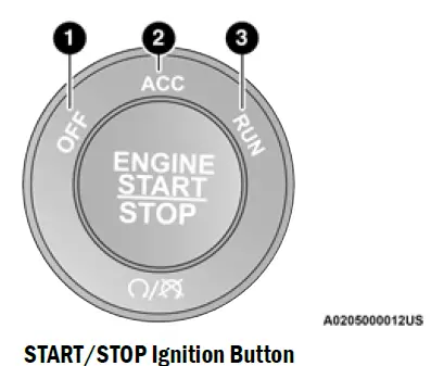
- OFF
- ACC
- ON/RUN
The push button ignition can be placed in the following modes:
OFF
- The engine is stopped.
- Some electrical devices (e.g. power locks, alarm, etc.) are still available.
- ACC
- Engine is not started.
- Some electrical devices are available (e.g. power windows).
- ON/RUN
- Driving position.
- All electrical devices are available
(e.g. climate controls, etc.). - START
- The engine will start.
NOTE
If the ignition switch does not change with the push of a button, the key fob may have a low or depleted battery. In this situation, a back up method can be
used to operate the ignition switch. Put the nose side (side opposite of the emergency key) of the key fob against the START/STOP ignition button and push to operate the ignition switch.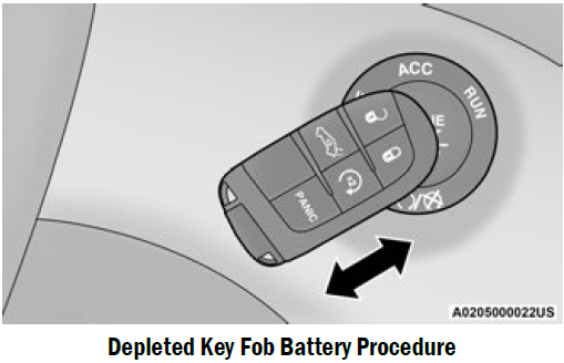
WARNING
- When exiting the vehicle, always remove the key fob from the vehicle and lock your vehicle.
- Never leave children alone in a vehicle, or with access to an unlocked vehicle.
- Allowing children to be in a vehicle unattended is dangerous for a number of reasons. A child or others could be seriously or fatally injured. Children should be warned not to touch the parking brake, brake pedal or the gear selector.
WARNING
- Do not leave the key fob in or near the vehicle, or in a location accessible to children, and do not leave the ignition of a vehicle equipped with Keyless Enter ‘n Go™ in the ON/RUN
position. A child could operate power
windows, other controls, or move the vehicle. - Do not leave children or animals inside parked vehicles in hot weather. Interior heat buildup may cause serious injury or death.
CAUTION
An unlocked vehicle is an invitation for thieves. Always remove key fob from the vehicle and lock all doors when leaving the vehicle unattended.
NOTE
- When opening the driver’s door with the ignition in ON/RUN (engine not running), a chime will sound to remind you to place the ignition in the
OFF position. In addition to the chime, the message will display “Ignition Or Accessory On” in the cluster. - For more information on proper engine starting procedures, see Ú page 82.
REMOTE START — IF EQUIPPED
 This system uses the key fob to start the engine conveniently from outside the vehicle while still maintaining security. The system has a range of 328 ft
(100 m). Remote Start is used to defrost windows in cold weather, and to reach a comfortable climate in all ambient conditions before the driver enters the
vehicle.
NOTE
Obstructions between the vehicle and key fob may reduce this range Ú page 322.
WARNING
- Do not start or run an engine in a closed garage or confined area. Exhaust gas contains Carbon Monoxide (CO) which is odorless and colorless. Carbon Monoxide is poisonous and can cause serious injury or death when inhaled.
- Keep key fobs away from children. Operation of the Remote Start system, windows, door locks or other controls could cause serious injury or death.
HOW TO USE REMOTE START
Push and release the remote start button on the key fob twice within five seconds. The vehicle doors will lock, the parking lights will flash, and the horn will chirp twice (if programmed). Then, the engine will start, and the vehicle will remain in the Remote Start mode for a 15 minute cycle. Pushing the remote start button a third time shuts the engine off.
To drive the vehicle, push the unlock button, and place the ignition in the ON/RUN position.
NOTE
- With Remote Start, the engine will only run for With Remote Start, the engine will only run for
- Remote Start can only be used twice.
- If an engine fault is present or fuel level is low, the vehicle will start and then shut down in 10 seconds.
- The parking lights will turn on and remain on during Remote Start mode.
- For security, power window and power sunroof operation (if equipped) are disabled when the vehicle is in the Remote Start mode.
- The ignition must be placed in the ON/RUN position before the Remote Start sequence can be repeated for a third cycle.
All of the following conditions must be met before the engine will remote start:
- Gear selector in PARK
- Doors closed
- Hood closed
- Trunk closed
- Hazard switch off
- Brake switch inactive (brake pedal not pressed)
- Battery at an acceptable charge level
- PANIC button not pushed
- System not disabled from previous remote start event
- Vehicle Security system indicator flashing
- Ignition in the OFF position
- Fuel level meets minimum requirement
- Vehicle Security system is not signaling an intrusion
- Malfunction Indicator Light (MIL) is not illuminated
WARNING
- Do not start or run an engine in a closed garage or confined area. Exhaust gas contains Carbon Monoxide (CO) which is odorless and colorless. Carbon Monoxide is poisonous and can cause serious injury or death when inhaled.
- Keep key fobs away from children. Operation of the Remote Start system, windows, door locks or other controls could cause serious injury or death.
TO EXIT REMOTE START MODE
To drive the vehicle after starting the Remote Start system, either push and release the unlock button on the key fob to unlock the doors, or unlock the vehicle using Keyless Enter ‘n Go™ — Passive Entry via the door handles, and disarm the Vehicle Security system (if equipped). Then, prior to the end of the 15 minute cycle, push and release the START/STOP ignition button.
The Remote Start system will turn the engine off if the Remote Start button on the key fob is pushed again, or if the engine is allowed to run for the entire 15 minute cycle. Once the ignition is placed in the ON/RUN position, the climate controls will resume the previously set operations
(temperature, blower control, etc.).
NOTE
- To avoid unintentional shutdowns, the system will disable for two seconds after receiving a valid Remote Start request.
- For vehicles equipped with the Keyless
Enter ‘n Go™ — Passive Entry feature, the message “Remote Start Active — Push Start Button” will show in the instrument cluster display until you push the START/STOP ignition button.
Remote Start will also cancel if any of the following occur:
- The engine stalls or engine speed exceeds 2500 RPM.
- Any engine warning lights come on.
- The Low Fuel Light turns on.
- The hood is opened.
- The hazard switch is pushed.
- The gear selector is moved out of PARK.
- The brake pedal is pressed.
REMOTE START FRONT DEFROST
ACTIVATION — IF EQUIPPED
When Remote Start is active, and the outside ambient temperature is 40°F (4.5°C) or below, the system will automatically activate front defrost for 15 minutes or less. The time is dependent on the ambient temperature. Once the timer expires, the system will automatically adjust the settings depending on ambient conditions. See “Remote Start Comfort Systems — If Equipped” in the next section for detailed operation.
REMOTE START COMFORT SYSTEMS — IF EQUIPPED
When Remote Start is activated, the front and rear defrost will automatically turn on in cold weather. The heated steering wheel and driver heated seat feature will turn on if selected in the comfort menu screen within Uconnect Settings Ú page 123. In warm weather, the driver vented seat feature will automatically turn on when Remote Start is activated, if programmed in the comfort menu screen. The vehicle will adjust the climate control settings depending on the outside ambient temperature.
Automatic Temperature Control (ATC) — If Equipped
The climate controls will be automatically adjusted to the optimal temperature and mode settings depending on the outside ambient temperature. This will occur until the ignition is placed in the ON/RUN position where the climate controls will resume their previous settings.
Manual Temperature Control (MTC) — If Equipped
- In ambient temperatures at 40°F (4.5°C) or below, the climate settings will default to maximum heat, with fresh air entering the cabin. If the front defrost timer expires, the vehicle will enter Mix Mode.
- In ambient temperatures from 40°F (4.5°C) to 78°F (26°C), the climate settings will be based on the last settings selected by the driver.
- In ambient temperatures at 78°F (26°C) or above, the climate settings will default to MAX A/C, Bi-Level Mode, with Recirculation on.
For more information on ATC, MTC, and climate control settings, see Ú page 51.
NOTE
These features will stay on through the duration of Remote Start until the ignition is placed in the ON/RUN position. The climate control settings will change if manually adjusted by the driver while the vehicle is in Remote Start mode, and exit auto-matic override. This includes the OFF button on the climate controls, which will turn the system off.
REMOTE START WINDSHIELD WIPER DE–ICER ACTIVATION — IF EQUIPPED
When Remote Start is active and the outside ambient temperature is less than 33°F (0.6°C), the Windshield Wiper Deicer will activate. Exiting Remote Start will resume its previous operation. If the Windshield Wiper De-Icer was active, the timer and operation will continue.
REMOTE START CANCEL MESSAGE — IF EQUIPPED
One of the following messages will display in the instrument cluster display if the vehicle fails to remote start or exits Remote Start prematurely:
- Remote Start Cancelled — Door Open
- Remote Start Cancelled — Hood Open
- Remote Start Cancelled — Fuel Low
- Remote Start Cancelled — Trunk Open
- Remote Start Disabled — Start Vehicle To Reset
The message will stay active until the ignition is placed in the ON/RUN position.
VEHICLE SECURITY SYSTEM — IF EQUIPPED
The Vehicle Security system monitors the vehicle doors for unauthorized entry and the Keyless Enter ‘n Go™ Ignition for unauthorized operation. While the Vehicle Security system is armed, interior switches for door locks and trunk release are disabled. If something triggers the alarm, the Vehicle Security system will provide the following audible and visible signals:
- The horn will pulse
- The turn signals will flash
- The Vehicle Security Light in the instrument cluster will flash.
TO ARM THE SYSTEM
Follow these steps to arm the Vehicle Security system:
- Make sure the vehicle’s ignition is placed in the OFF position.
- Perform one of the following methods to lock the vehicle:
- Push lock on the interior power door lock switch with the driver and/or passenger door open.
- Push the lock button on the exterior Passive Entry door handle with a valid key fob avail-able in the same exterior zone Ú page 24.
- Push the lock button on the key fob.
- If any doors are open, close them.
TO DISARM THE SYSTEM
The Vehicle Security system can be disarmed using any of the following methods:- Push the unlock button on the key fob.
- Grab the Passive Entry door handle to unlock the door Ú page 24.
- Push the START/STOP ignition button (requires at least one valid key fob in the vehicle).
NOTE
- The driver’s door key cylinder and the trunk button on the key fob cannot arm or disarm the Vehicle Security system.
- When the Vehicle Security system is armed, the interior power door lock switches will not unlock the doors.
The Vehicle Security system is designed to protect your vehicle. However, you can create conditions where the system will give you a false alarm. If one of the previously described arming sequences has occurred, the Vehicle Security system will arm, regardless of whether you are in the vehicle or not. If you remain in the vehicle and open a door, the alarm will sound. If this occurs, disarm the Vehicle Security system. If the Vehicle Security system is armed and the battery becomes disconnected, the Vehicle Security system will remain armed when the battery is reconnected; the exterior lights will flash, and the horn will sound. If this occurs, disarm the Vehicle Security system.
REARMING THE SYSTEM
If something triggers the alarm and no action is taken to disarm it, the Vehicle Security system will turn the horn off after a 29 second cycle (with five seconds between cycles and up to eight cycles if the trigger remains active) and then rearm itself.
SECURITY SYSTEM MANUAL OVERRIDE
The Vehicle Security system will not arm if you lock the doors using the manual door lock.
TAMPER ALERT
If something has triggered the Vehicle Security system in your absence, the horn will sound three times and the exterior lights will blink three times when you disarm the Vehicle Security system.
DELUXE VEHICLE SECURITY SYSTEM — IF EQUIPPED
The Deluxe Vehicle Security system monitors the doors, hood latch, and trunk for unauthorized entry and the ignition switch for unauthorized operation. The system also includes a dual function intrusion sensor and vehicle tilt sensor. The intrusion sensor monitors the vehicle interior for motion. The vehicle tilt sensor monitors the vehicle for any tilting actions (tow away, tire removal, ferry transport, etc.). If a perimeter violation triggers the security system, the horn will sound for 29 seconds and the exterior lights will flash followed by approximately five seconds of no activity. This will continue for eight cycles if no action is taken to disarm the system.
TO ARM THE SYSTEM
Follow these steps to arm the security system:
- Make sure the vehicle ignition system is OFF.
- Perform one of the following methods to lock the vehicle:
- Push lock on the interior power door lock switch with the driver and/or passenger door open.
- Push the lock button on the exterior Passive
- Entry door handle with a key fob available in the same exterior zone Ú page 24.
- Push the lock button on the key fob.
- If any doors, windows, or the sunroof (if equipped) are open, close them.
NOTE
- When armed, the interior motion sensor detects movement within the vehicle’s interior, including moving objects (i.e. people and pets) and air currents through open windows or the sunroof. The windows and sunroof should be closed, and moving objects should not be left in the vehicle when the intrusion detection is armed, otherwise false alarms can occur.
- Once the security system is armed, it remains in that state until you disarm it by following either of the disarming procedures described. If a power loss occurs after arming the system, you must disarm the system after restoring power to prevent alarm activation.
- The ultrasonic intrusion sensor (motion detector) actively monitors your vehicle every time you arm the Vehicle Security system. If you prefer, you can turn off the ultrasonic intrusion sensor when arming the Vehicle Security system. To do so, push the lock button on the key fob three times within 15 seconds of arming the system (while the Vehicle Security Light is flashing rapidly). The vehicle will remain locked but disable the alarm in the case of repeated false alarms due to ambient conditions.
TO DISARM THE SYSTEM
The Vehicle Security system can be disarmed using any of the following methods:
- Push the unlock button on the key fob.
- Grab the Passive Entry door handle to unlock the door Ú page 24.
- Cycle the vehicle ignition system out of the OFF position by pushing the START/STOP ignition button (requires at least one valid key fob in the vehicle).
NOTE
- The driver’s door key cylinder and the trunk button on the key fob cannot arm or disarm the Vehicle Security system.
- The Vehicle Security system remains armed during power trunk entry. If a valid key fob or key fob passive entry is used to open the trunk, the motion sensing will be suppressed until after the trunk is closed. If someone enters the vehicle through the trunk and opens any door, the alarm will sound.
- When the Vehicle Security system is armed, the interior power door lock switches will not unlock the doors.
- The ultrasonic intrusion sensor (motion detector) actively monitors your vehicle every time you arm the Vehicle Security system. If you prefer, you can turn off the ultrasonic intrusion sensor when arming the Vehicle Security system. To do so, push the lock button on the key fob three times within 15 seconds of arming the system (while the Vehicle Security Light is flashing rapidly). The vehicle will remain locked but disable the alarm in the case of repeated false alarms due to ambient conditions.
The Vehicle Security system is designed to protect your vehicle; however, you can create conditions where the system will give you a false alarm. If one of the previously described arming sequences has occurred, the Vehicle Security system will arm regardless of whether you are in the vehicle or not. If you remain in the vehicle and open a door, the alarm will sound. If this occurs, disarm the Vehicle Security system.
If the Vehicle Security system is armed and the battery becomes disconnected, the Vehicle Security system will remain armed when the battery is reconnected; the exterior lights will flash and the horn will sound. If this occurs, disarm the Vehicle Security system.
SECURITY SYSTEM MANUAL OVERRIDE
The Vehicle Security system will not arm if you lock the doors using the manual door lock.
DOORS
MANUAL DOOR LOCKS
The power door locks can be manually locked from inside the vehicle by using the door lock knob. To lock each door, push the door lock knob on each door trim panel downward. To unlock each door, pull the door lock knob on each door trim panel upward.
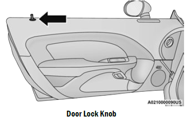
Door Lock Knob
If the door lock knob is down when you shut the door, the door will lock. Therefore, make sure the key fob is not inside the vehicle before closing the door.
NOTE
Manually locking the vehicle will not arm the Vehicle Security system.
WARNING
- For personal security and safety in the event of a collision, lock the vehicle doors before you drive as well as when you park and leave the vehicle.
- Before exiting a vehicle, always shift the automatic transmission into PARK or the manual transmission into FIRST gear or REVERSE, apply the parking brake, place the ignition in the OFF position, remove the key fobs from the vehicle and lock all doors, and lock your vehicle.
- When leaving the vehicle, always remove the key from the ignition and lock your vehicle. Unsupervised use of vehicle equipment may cause severe personal injuries and death.
- Never leave children alone in a vehicle, or with access to an unlocked vehicle. Allowing children to be in a vehicle unattended is dangerous for a number of reasons. A child or others could be seriously or fatally injured. Children should be warned not to touch the parking brake, brake pedal or gear selector.
WARNING
- Do not leave the key fob in or near the vehicle, or in a location accessible to children, and do not leave the ignition of a vehicle equipped with Keyless Enter ‘n Go™ in the ACC or ON/RUN position. A child could operate power windows, other controls, or move the vehicle.
POWER DOOR LOCKS
The power door lock switches are located on each door trim panel. Push the switch to lock or unlock the doors.
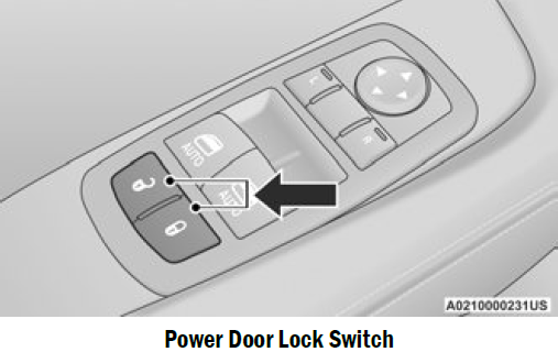
Power Door Lock Switch
If you push the power door lock switch while the ignition is on, and either door is open, the power locks will not operate. This prevents you from accidentally locking the key fob in the vehicle.
Turning off the ignition or closing the door will allow the locks to operate.
NOTE
If the key fob is located next to a mobile phone, laptop, or other electronic device, the wireless signal may get blocked, and the driver’s door may not unlock automatically. If a door is open with the ignition either placed in the ACC or ON/RUN (engine not running) position, a chime will sound as a reminder.
KEYLESS ENTER ‘N GO™ — PASSIVE ENTRY
The Passive Entry system is an enhancement to the vehicle’s key fob and a feature of Keyless Enter ‘n Go™. This feature allows you to lock and unlock the vehicle’s door(s) without having to push the key fob lock or unlock buttons.
NOTE
- Passive Entry may be programmed on/off through Uconnect Settings Ú page 123.
- The key fob may not be detected by the vehicle Passive Entry system if it is located next to a mobile phone, laptop or other electronic device; these devices may block the key fob’s wireless signal and prevent the Passive Entry handle from locking/unlocking the vehicle.
- Passive Entry Unlock initiates illuminated approach (low beams, license plate lamp, posi-tion lamps) for whichever time duration is set between 0, 30, 60 or 90 seconds. Passive Entry Unlock also initiates two flashes of the turn signal lamps.
- If wearing gloves, or if it has been raining/snowing on the Passive Entry door handle, the unlock sensitivity can be affected, resulting in a slower response time.
- If the vehicle is unlocked by Passive Entry and no door is opened within 60 seconds, the vehicle will relock and (if equipped) will arm the Vehicle Security system.
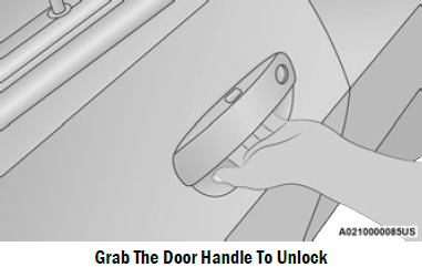
To Unlock From The Driver Or Passenger Side
With a Passive Entry key fob within 5 ft (1.5 m) of the door handle, grab the handle to unlock the vehicle. Grabbing the driver’s door handle will unlock the driver door automatically. Grabbing the passenger door handle will unlock both doors automatically. The interior door panel lock knob will raise when the door is unlocked.
NOTE
- Either the driver door only or all doors will unlock when you grab hold of the front driver’s door handle, depending on the selected setting in the Uconnect system Ú page 123.
- All doors will unlock when the front passenger door handle is grabbed regardless of the driver’s door unlock preference setting.
Frequency Operated Button Integrated Key (FOBIK-Safe)
To minimize the possibility of unintentionally locking a Passive Entry key fob inside your vehicle, the Passive Entry system is equipped with an automatic door unlock feature which will function if the ignition is in the OFF position. There are three situations that trigger a FOBIK-Safe search in any Passive Entry vehicle.
- A lock request is made by a valid Passive Entry key fob while a door is open.
- A lock request is made by the Passive Entry door handle while a door is open.
- A lock request is made by the door panel switch while the door is open.
When any of these situations occur, after all open doors are shut, the FOBIK-Safe search will be executed. If it detects a Passive Entry key fob inside the car, and it does not detect any Passive Entry key fobs outside the car, the car will unlock and alert the customer.
NOTE
The vehicle will only unlock the doors when a valid Passive Entry key fob is detected inside the vehicle, and no valid Passive Entry key fob is detected outside the vehicle. The vehicle will not unlock the doors when any of the following conditions are true:
- The doors are manually locked using the door lock knobs.
- Three attempts are made to lock the doors using the door panel switch and then the doors are closed.
- There is a valid Passive Entry key fob outside the vehicle and within 5 ft (1.5 m) of either Passive Entry door handle.
To Enter The Trunk
With a Passive Entry key fob within 5 ft (1.5 m) of the deck lid, push the button located on the center of the light bar which is located on the deck lid above the license plate.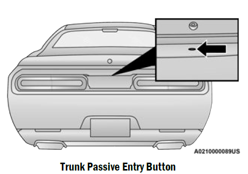
Trunk Passive Entry Button
NOTE
If you inadvertently leave your vehicle’s Passive Entry key fob in the trunk and try to close the deck lid, the deck lid will automatically unlatch, unless another one of the vehicle’s Passive Entry key fobs is outside the vehicle and within 5 ft (1.5 m) of the deck lid.
To Lock The Vehicle’s Doors
With one of the vehicle’s Passive Entry key fobs within 5 ft (1.5 m) of either door handle, pushing the Passive Entry lock button will lock both doors.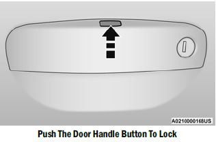
Do NOT grab the door handle, when pushing the door handle button. This could unlock the door(s).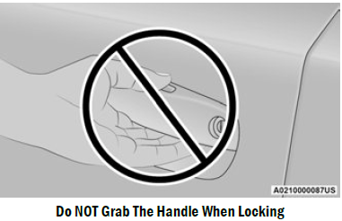
NOTE
- After pushing the door handle button, you must wait two seconds before you can lock or unlock the doors, using either Passive Entry door handle. This is done to allow you to check if the vehicle is locked by pulling the door handle, without the vehicle unlocking.
- The Passive Entry system will not operate if the key fob battery is depleted.
The vehicle doors can also be locked by using the key fob lock button or the lock button located on the vehicle’s interior door panel Ú page 322.
AUTOMATIC UNLOCK DOORS ON EXIT
The doors will unlock automatically on vehicles with power door locks if:
- The Automatic Unlock Doors On Exit feature is enabled within Uconnect Settings Ú page 123.
- The driver door is opened.
- The doors were not previously unlocked. NOTE:
- The doors will also unlock automatically when the gear selector was not previously in the PARK position, then is placed into the PARK position.
- Use the Automatic Unlock Doors On Exit feature in accordance with local laws.
AUTOMATIC DOOR LOCKS — IF EQUIPPED
The auto door lock feature default condition is enabled. When enabled, the door locks will lock automatically when the vehicle’s speed exceeds 15 mph (24 km/h). The auto door lock feature can be enabled or disabled by an authorized dealer per written request of the customer. Please see an authorized dealer for service.
STEERING WHEEL
MANUAL TILT/TELESCOPING STEERING COLUMN — IF EQUIPPED
This feature allows you to tilt the steering column upward or downward. It also allows you to lengthen or shorten the steering column. The tilt/telescoping lever is located below the steering wheel at the end of the steering column.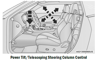
To unlock the steering column, pull the lever downward (toward the floor). To tilt the steering column, move the steering wheel upward or downward as desired. To lengthen or shorten the steering column, pull the steering wheel outward or push it inward as desired. To lock the steering column in position, push the lever upward until fully engaged.
WARNING
Do not adjust the steering column while driving. Adjusting the steering column while driving or driving with the steering column unlocked, could cause the driver to lose control of the vehicle. Failure to follow this warning may result in serious injury or death.
POWER TILT/TELESCOPING STEERING COLUMN — IF EQUIPPED
This feature allows you to tilt the steering column upward or downward. It also allows you to lengthen or shorten the steering column. The power tilt/telescoping steering column control is located below the multifunction lever on the steering column.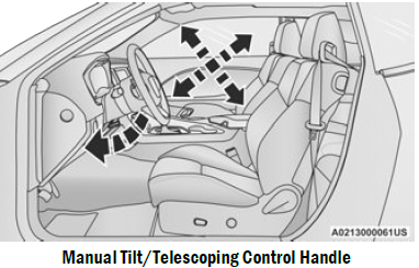
Power Tilt/Telescoping Steering Column Control
Use the four-way control to adjust the steering column.
NOTE
For vehicles equipped with Driver Memory Settings, use the key fob or the memory switch on the driver’s door trim panel to return the tilt/telescopic steering column to saved positions.
WARNING
Do not adjust the steering column while driving. Adjusting the steering column while driving or driving with the steering column unlocked, could cause the driver to lose control of the vehicle. Failure to follow this warning may result in serious injury or death.
HEATED STEERING WHEEL — IF EQUIPPED
 The steering wheel contains a heating element that helps warm your hands in cold weather. The heated steering wheel has only one temperature setting. Once the heated steering wheel has been turned on, it will stay on for an average of 80 minutes before automatically shutting off. This time will vary based on environmental temperatures. The heated steering wheel can shut off early or may not turn on when the steering wheel is already warm. The heated steering wheel button is located within the Uconnect system. You can access the button through the climate screen or the controls screen.
- Press the heated steering wheel button once to turn the heating element on.
- Press the heated steering wheel button a second time to turn the heating element off.
NOTE
The engine must be running for the heated steering wheel to operate For information on use with the Remote Start system, see Ú page 20.
WARNING
- Persons who are unable to feel pain to the skin because of advanced age, chronic illness, diabetes, spinal cord injury, medication, alcohol use, exhaustion, or other physical conditions must exercise care when using the steering wheel heater. It may cause burns even at low temperatures, especially if used for long periods.
- Do not place anything on the steering wheel that insulates against heat, such as a blanket or steering wheel covers of any type and material. This may cause the steering wheel heater to overheat.
UCONNECT VOICE RECOGNITION
INTRODUCING VOICE RECOGNITION
Start using Uconnect Voice Recognition with these helpful quick tips. It provides the key Voice Commands and tips you need to know to control your vehicle’s Voice Recognition (VR) system.
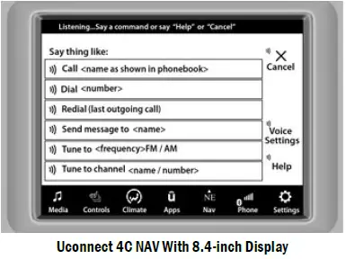
Uconnect 4C NAV With 8.4-inch Display
If you see the NAV icon on the bottom bar or in the Apps menus of your 8.4-inch touchscreen, you have the Uconnect 4C NAV system. If not, you have a Uconnect 4C with 8.4-inch display system.
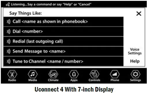
BASIC VOICE COMMANDS
The basic Voice Commands below can be given at any point while using your Uconnect system.
Push the VR button . After the beep, say:
- “Cancel” to stop a current voice session
- “Help” to hear a list of suggested Voice Commands
- “Repeat” to listen to the system prompts again.
Notice the visual cues that inform you of your VR system’s status. Cues appear on the touchscreen.
GET STARTED
The Voice Recognition (VR) button is used to activate/deactivate your Voice Recognition system.
Helpful hints for using Voice Recognition:
- Reduce background noise. Wind and passenger conversations are examples of noise that may impact recognition.
- Speak clearly at a normal pace and volume while facing straight ahead.
- Each time you give a Voice Command, you must first push the Voice Recognition (VR) button, wait until after the beep, then say your Voice Command. You can interrupt the help message or system prompts by pushing the VR button and saying a Voice Command from the current category.
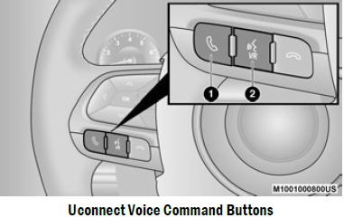
- Push To Start Or Answer A Phone Call And Send Or Receive A Text
- Push The Voice Recognition Button To Begin Radio, Media, Navigation, And Climate Functions.
ADDITIONAL INFORMATION
© 2021 FCA US LLC. All rights reserved. Mopar and Uconnect are registered trademarks and Mopar Owner Connect is a trademark of FCA US LLC. Sirius XM® and all related marks and logos are trademarks of Sirius XM® Radio Inc. Ú page 322.
Uconnect System Support
- US residents visit www.DriveUconnect.com or call: 1-877-855-8400 (24 hours a day 7 days a week)
- Canadian residents visit www.DriveUcon-nect.ca or call: 1-800-465-2001 (English) or
1- 800-387-9983 (French) - SiriusXM Guardian™ services support:
- US residents visit www.driveuconnect.com/siriusxm-guardian or call: 1-844-796-4827.
- Canadian residents visit https://www.driveuconnect.ca/en/sirius-xm-guardian or call: 1- 877-324-9091
DRIVER MEMORY SETTINGS — IF EQUIPPED
This feature allows the driver to save up to two different memory profiles for easy recall through a memory switch. Each memory profile saves desired position settings for the following features:
- Driver seat cushion
- Easy Entry/Exit seat operation (if equipped)
- Side mirrors
- Power tilt/telescoping steering column
(if equipped) - A set of desired radio station presets
- NOTE
Your vehicle is equipped with two key fobs, each can be linked to either memory position 1 or 2. Be sure to program the radio presets prior to programming the memory settings.
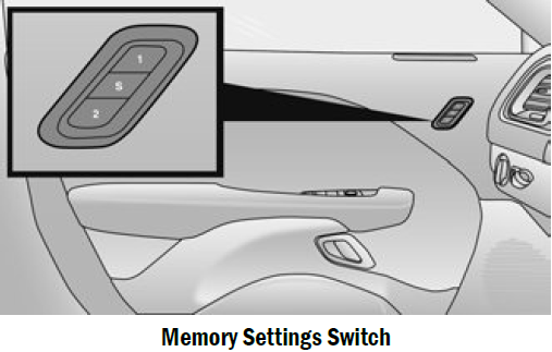
The memory settings switch is located on the driver’s door trim panel. The switch consists of three buttons:
- The set (S) button, which is used to activate the memory save function.
- The (1) and (2) buttons which are used to recall either of two saved memory profiles.
PROGRAMMING THE MEMORY FEATURE
To create a new memory profile, perform the following:
NOTE
Saving a new memory profile will erase the selected profile from memory.
- Place the vehicle’s ignition in the ON/RUN position (do not start the engine).
- Adjust all memory profile settings to desired preferences (i.e., seat, side mirror, power tilt and telescopic steering column [if equipped], and radio station presets).
- Push and release the set (S) button on the memory switch, and then push the desired memory button (1 or 2) within five seconds. The instrument cluster display will display which memory position has been set.
NOTE
Memory profiles can be set without the vehicle in PARK, but the vehicle must be in PARK to recall a memory profile.
LINKING AND UNLINKING THE KEY FOB
TO MEMORY
Your key fobs can be programmed to recall one of two saved memory profiles.
NOTE
Before programming your key fobs you must select the “Personal Settings Linked To Key Fob” feature through the Uconnect system Ú page 123. To program your key fobs, perform the following:
- Place the vehicle’s ignition in the OFF position.
- Select a desired memory profile, 1 or 2.
- Once the profile has been recalled, push and release the set (S) button on the memory switch.
- Within five seconds, push and release button
- or (2) accordingly. “Memory Profile Set” (1 or 2) will display in the instrument cluster.
- Push and release the lock button on the key fob within 10 seconds.
NOTE
Your key fob can be unlinked from your memory settings by pushing the set (S) button, followed by pushing the unlock button on the key fob within 10 seconds.
MEMORY POSITION RECALL
NOTE
If a recall is attempted when the vehicle is not in PARK, a message will be displayed in the instrument cluster display. To recall the memory settings for driver one or two, push the desired memory button number (1 or 2) or the unlock button on the key fob linked to the desired memory position. A recall can be canceled by pushing any of the memory buttons (S, 1, or 2) during a recall. When a recall is canceled, the driver seat will stop moving. A delay of one second will occur before another recall can be selected.
NOTE
If the vehicle is equipped with Passive Entry, the memory settings are recalled when using Passive Entry to unlock the driver’s door with a linked key fob.
SEATS
Seats are a part of the Occupant Restraint system of the vehicle.
WARNING
- It is dangerous to ride in a cargo area, inside or outside of a vehicle. In a collision, people riding in these areas are more likely to be seri-ously injured or killed.
- Do not allow people to ride in any area of your vehicle that is not equipped with seats and seat belts. In a collision, people riding in these areas are more likely to be seriously injured or killed.
- Be sure everyone in your vehicle is in a seat and using a seat belt properly.
MANUAL ADJUSTMENT (FRONT SEATS) — IF EQUIPPED
WARNING
Adjusting a seat while the vehicle is moving is dangerous. The sudden movement of the seat could cause you to lose control. The seat belt might not be adjusted properly and you could be injured. Adjust the seat only while the vehicle is parked.
WARNING
Do not ride with the seatback reclined so that the shoulder belt is no longer resting against your chest. In a collision you could slide under the seat belt and be seriously or even fatally injured. Use the recliner only when the vehicle is parked.
Manual Front Seat Forward/Rearward Adjustment
The seat can be adjusted forward or rearward by using a bar located by the front of the seat cushion, near the floor.
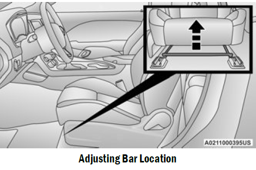
While sitting in the seat, lift up on the bar located under the seat cushion and move the seat forward or rearward. Release the bar once you have reached the desired position. Then, using body pressure, move forward and rearward on the seat to be sure that the seat adjusters have latched.
WARNING
- Adjusting a seat while driving may be dangerous. Moving a seat while driving could result in loss of control which could cause a collision and serious injury or death.
- Seats should be adjusted before fastening the seat belts and while the vehicle is parked. Serious injury or death could result from a poorly adjusted seat belt.
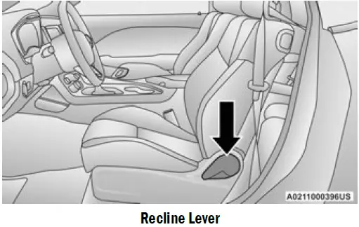
Manual Front Seat Recline
To adjust the seatback, lift the lever located on the outboard side of the seat, lean back to the desired position and release the lever. To return the seatback, lift the lever, lean forward and release the lever.
WARNING
Do not ride with the seatback reclined so that the shoulder belt is no longer resting against your chest. In a collision you could slide under the seat belt, which could result in serious injury or death.
MANUAL ADJUSTMENT (REAR SEATS)
WARNING
Do not pile luggage or cargo higher than the top of the seatback. This could impair visibility or Folding Rear Seatback Loop Locations
become a dangerous projectile in a sudden stop or collision.
Folding Rear Seat
The rear seatbacks can be folded forward to provide additional storage area. Pull on the loops located on the upper part of the rear seatback to fold down either or both seatbacks. These loops can be tucked away when not in use.
NOTE
You may experience deformation in the seat cushion from the seat belt buckles if the seats are left folded for an extended period of time. This is normal and, by simply unfolding the seats to the open position, over time the seat cushion will return to its normal shape.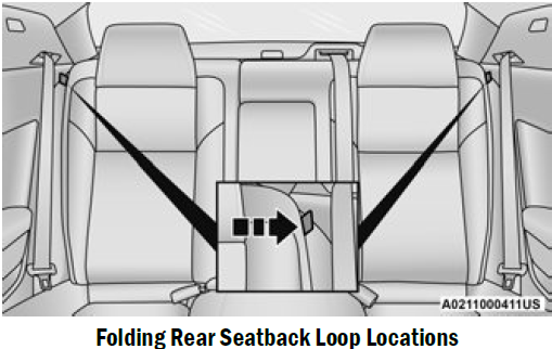
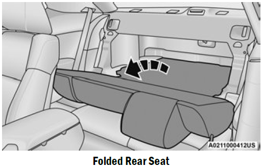
When the seatback is folded to the upright position, make sure it is latched by strongly pulling on the top of the seatback above the seat strap.
WARNING
- Be certain that the seatback is securely locked into position. If the seatback is not securely locked into position, the seat will not provide the proper stability for child seats and/or passengers. An improperly latched seat could cause serious injury.
- The cargo area in the rear of the vehicle (with the rear seatbacks in the locked-up or folded down position) should not be used as a play area by children when the vehicle is in motion. They could be seriously injured in a collision. Children should be seated and using the proper restraint system.
POWER ADJUSTMENT (FRONT SEATS) — IF EQUIPPED
The power seat switches are located on the outboard side of the front seats. The power seat switches control the movement of the seat. Vehicles equipped with power seat controls, will have a manual recline lever.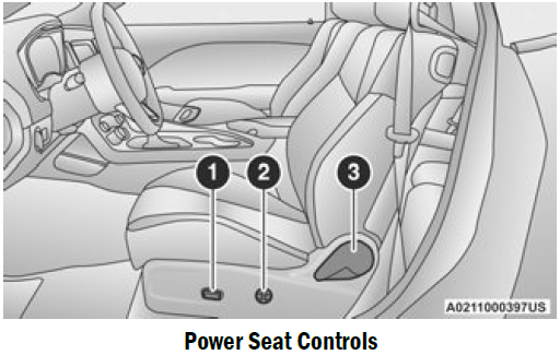
Power Seat Controls
- Power Seat Switch
- Power Lumbar Switch
- Manual Recline Lever
Adjusting The Seat Forward Or Rearward
The seat can be adjusted both forward and rearward by using the power seat switch. The seat will move in the direction of the switch. Release the switch when the desired position has been reached.
Adjusting The Seat Up Or Down
The height of the seats can be adjusted up or down by using the power seat switch. The seat will move in the direction of the switch. Release the switch when the desired position has been reached.
Tilting The Seat Up Or Down
The angle of the seat cushion can be adjusted up or down using the power seat switch. The front of the seat cushion will move in the direction of the switch. Release the switch when the desired position has been reached.
Power Lumbar — If Equipped
Vehicles equipped with power driver or passenger seats may also be equipped with power lumbar. The power lumbar switch is located on the outboard side of the power seat. Push the switch forward or rearward to increase or decrease the lumbar support.
Easy Entry/Exit Seat — If Equipped
This feature provides automatic driver seat positioning to enhance driver mobility when entering and exiting the vehicle.
The distance the driver seat moves depends on where you have the driver seat positioned when you place the vehicle’s ignition in the OFF position.
- When you place the vehicle’s ignition in the OFF position, the driver seat will move about
2.4 inches (60 mm) rearward if the driver seat position is greater than or equal to 2.7 inches (67.7 mm) forward of the rear stop. The seat will return to its previously set position when you place the vehicle’s ignition in the ACC or RUN position. - The Easy Entry/Exit feature is disabled when the driver seat position is less than 0.9 of an inch (22.7 mm) forward of the rear stop. At this position, there is no benefit to the driver by moving the seat for Easy Exit or Easy Entry.
- When enabled in Uconnect Settings, Easy Entry and Easy Exit positions are stored in each memory setting profile Ú page 30.
- NOTE
The Easy Entry/Exit feature is enabled or disabled through the programmable features in the Uconnect system Ú page 123. - HEATED SEATS — IF EQUIPPED
On some models, the front seats may be equipped with heaters located in the seat cushions and seatbacks. - WARNING
- Persons who are unable to feel pain to the skin because of advanced age, chronic illness, diabetes, spinal cord injury, medication, alcohol use, exhaustion or other physical condition must exercise care when using the seat heater. It may cause burns even at low temperatures, especially if used for long periods of time.
- skin because of advanced age, chronic illness, diabetes, spinal cord injury, medication, alcohol use, exhaustion or other physical condition must exercise care when using the seat heater. It may cause burns even at low temperatures, especially if used for long periods of time.
Front Heated Seats
 The front heated seats control buttons are located within the Uconnect system. You can gain access to the control buttons through the climate screen and the controls screen. You can choose from HI, LO, or OFF heat settings. The indicator arrows in touchscreen buttons indicate the level of heat in use. Two indicator arrows will illuminate for HI, and one for LO. Turning the heating elements off will return the user to the radio screen.
- Press the heated seat button once to turn the HI setting on.
- Press the heated seat button a second time to turn the LO setting on.
- Press the heated seat button a third time to turn the heating elements off.
NOTE
- Once a heat setting is selected, heat will be felt within two to five minutes.
- The engine must be running for the heated seats to operate.
- If the HI-level setting is selected, the system will automatically switch to LO-level after approximately 60 minutes of continuous operation. At that time, the display will change from HI to LO, indicating the change. The LO-level setting will turn off automatically after approximately 45 minutes.
For information on use with the Remote Start system, see Ú page 20.
WARNING
- Persons who are unable to feel pain to the skin because of advanced age, chronic illness, diabetes, spinal cord injury, medication, alcohol use, exhaustion or other physical condition must exercise care when using the seat heater. It may cause burns even at low temperatures, especially if used for long periods of time.
- Do not place anything on the seat or seatback that insulates against heat, such as a blanket or cushion. This may cause the seat heater to overheat. Sitting in a seat that has been over-heated could cause serious burns due to the increased surface temperature of the seat.
FRONT VENTILATED SEATS — IF EQUIPPED
The ventilated seats are equipped with fans that can be controlled through the climate and control screen in the Uconnect system. The fans operate at two speeds, HI and LO.
- Press the ventilated seat button once to choose HI.
- Press the ventilated seat button a second time to choose LO.
- Press the ventilated seat button a third time to turn the ventilated seat off.
NOTE
The engine must be running for the ventilated seats to operate.
For information on use with the Remote Start system, see Ú page 20.
VEHICLES WITHOUT PASSENGER SEATING INSTALLED
All passenger occupants within the vehicle must be in a seat equipped with a Seat Belt System and Head Restraint for the safety of the passenger. If the passenger and/or rear seats have been removed, do not ride in those areas.
This vehicle has been designed to maximize total performance. In doing so, the deletion of passenger seats and/or rear seat may affect the Noise, Vibration, and Harshness (NVH) characteristics. As a result, the interior will be louder overall.
WARNING
- If the passenger and/or rear seats have been removed, do not ride in those areas. In a collision, people riding in these areas are more likely to be seriously injured or killed.
- If this vehicle was not factory equipped with a passenger seat, NEVER attempt to install a passenger seat because the safety systems, including the air bags and seat belt, may not properly protect you.
- It is dangerous to ride in a cargo area, inside or outside of a vehicle. In a collision, people riding in this area are more likely to be seriously injured or killed.
- Only ride in available seating positions equipped with seat belt systems. Always properly wear your seat belt. Failure to do so could result in an increased risk of serious injury or death in the event of an accident.
WARNING
- Be sure everyone in your vehicle is in a seat and using a seat belt properly. Occupants, including the driver, should always wear their seat belts whether or not an air bag is also provided at their seating positions to minimize the risk of severe injury or death in the event of a crash.
- All occupants, including the driver, should not operate a vehicle or sit in a vehicle’s seat if the head restraints are not in place of their proper positions in order to minimize the risk of neck injury in the event of a crash.
- Head restraints should never be adjusted while the vehicle is in motion. Driving a vehicle with the head restraints improperly adjusted or removed could cause serious injury or death in the event of a collision.
PASSENGER SEAT EASY ENTRY
On the passenger seat, pull forward on the lever located on the side of the seatback in order to dump the seatback and slide the seat forward. You can also temporarily remove the seat belt from the guide loop on the seat and allow the seat belt to retract out of the way. This allows for easier access to the rear seat. To return the seat to a normal seating position, first return the seatback to its original recline location and then slide the entire seatback to the preset lock position.
NOTE
- The front passenger seat needs to slide back to a preset position for the fore/aft adjuster to be properly locked. For example, if the front passenger has the seat adjusted full rear and exits the vehicle to let a rear passenger enter using the easy entry handle, the fore/aft adjuster needs to slide back about 2/3 of the way rearward to hit the lock position. If the adjuster is not returned to this preset position, the seat will appear to be loose.
- If the front passenger uses the easy entry handle and then lifts up the recliner handle without moving the seatback to its original preset position, the recliner will not lock until it is moved to the full recline position.
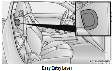
Driver’s Side Easy Entry
The easy entry lever on the outboard side of the driver’s seatback will dump the seatback forward to allow for easier access to the rear seats. The seat bottom will not slide forward as the passenger side easy entry will. If needed, use the driver’s side seat control to slide forward. To return the seat to the normal position, push the seatback up and it will lock into the previously set recline position. Then if needed, use the seat control to adjust the forward/rearward position.
HEAD RESTRAINTS
Head restraints are designed to reduce the risk of injury by restricting head movement in the event of a rear impact. Head restraints should be adjusted so that the top of the head restraint is located above the top of your ear.
WARNING
- All occupants, including the driver, should not operate a vehicle or sit in a vehicle’s seat until the head restraints are placed in their proper positions in order to minimize the risk of neck injury in the event of a crash.
- Head restraints should never be adjusted while the vehicle is in motion. Driving a vehicle with the head restraints improperly adjusted or removed could cause serious injury or death in the event of a collision.
NOTE
Do not reverse the head restraints (making the rear of the head restraint face forward) in an attempt to gain additional clearance to the back of your head.
Reactive Head Restraints — Front Seats
The front driver and passenger seats are equipped with Reactive Head Restraints (RHR). In the event of a rear impact, the RHR will automatically extend forward minimizing the gap between the back of the occupants head and the RHR. The RHR will automatically return to their normal position following a rear impact. If the RHR do not return to their normal position, see an authorized dealer immediately.
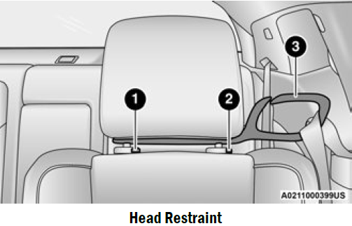
- Release Button
- Adjustment Button
- Seat Belt Loop
To raise the head restraint, pull upward on the head restraint. To lower the head restraint, push the adjustment button located at the base of the head restraint and push downward on the head restraint. To remove the head restraint, remove the seat belt from the seat belt loop. Raise the head restraint as far as it can go. Then, push the adjustment button and the release button at the base of each post while pulling the head restraint up. To reinstall the head restraint, put the head restraint posts into the holes while pushing the adjustment button and release button. Then, adjust it to the appropriate height.
NOTE
It may be necessary to recline the front seat before removing the head restraint to provide enough clearance from the roof.
WARNING
- A loose head restraint thrown forward in a collision or hard stop could cause serious injury or death to occupants of the vehicle. Always securely stow removed head restraints in a location outside the occupant compartment.
- ALL the head restraints MUST be reinstalled in the vehicle to properly protect the occupants. Follow the reinstallation instructions above prior to operating the vehicle or occupying a seat.
- Do not place items over the top of the Reactive Head Restraint, such as coats, seat covers or portable DVD players. These items may interfere with the operation of the Reactive Head Restraint in the event of a collision and could result in serious injury or death.
Rear Head Restraints
The rear outboard head restraints are non-adjustable and are designed to reduce the risk of injury by restricting head movement in the event of a rear impact.
MIRRORS
INSIDE REARVIEW MIRROR
Automatic Dimming Mirror
The rearview mirror can be adjusted up, down, left, and right. The mirror should be adjusted to center on the view through the rear window. This mirror automatically adjusts for headlight glare from vehicles behind you.
NOTE
The Automatic Dimming Mirror feature is disabled when the vehicle is in REVERSE to improve the driver’s rear view. The Automatic Dimming feature can be turned on or off through the touchscreen.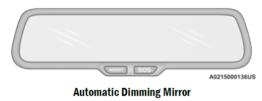
CAUTION
To avoid damage to the mirror during cleaning, never spray any cleaning solution directly onto the mirror. Apply the solution onto a clean cloth and wipe the mirror clean.
- ILLUMINATED VANITY MIRRORS
To access an illuminated vanity mirror, flip down one of the visors and lift the cover.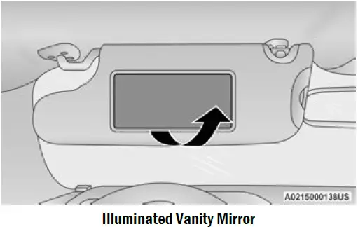
Sun Visor “Slide-On-Rod” And Extender Feature
The sun visor “Slide-On-Rod” feature allows for additional flexibility in positioning the sun visor to block out the sun.
- Fold down the sun visor.
- Unclip the visor from the corner clip.
- Pivot the sun visor toward the side window.
- Extend the sun visor for additional sun blockage.
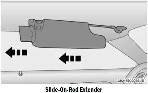 To use the extender feature of the sun visor, grab the extender which is located at the rear of the visor and pull rearward.
OUTSIDE MIRRORS
The outside mirror(s) can be adjusted to the center of the adjacent lane of traffic to achieve the optimal view.
NOTE
The passenger side convex outside mirror will give a much wider view to the rear, and especially of the lane next to your vehicle.
WARNING
Vehicles and other objects seen in an outside convex mirror will look smaller and farther away than they really are. Relying too much on side convex mirrors could cause you to collide with another vehicle or other object. Use your inside mirror when judging the size or distance of a vehicle seen in a side convex mirror.
POWER MIRRORS
The power mirror switch is located on the driver’s side door trim panel. The power mirror controls consist of mirror select buttons and a four-way mirror control switch. To adjust a mirror, push the mirror select button for the mirror that you want to adjust. Using the mirror control switch, push on any of the four arrows for the direction that you want the mirror to move.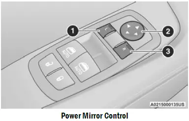
Power Mirror Control
- Left Mirror Selection
- Mirror Adjustment
- Right Mirror Selection
NOTE
A light in the select button will illuminate indicating the mirror is activated and can be adjusted.
HEATED MIRRORS — IF EQUIPPED
 These mirrors are heated to melt frost or ice. This feature will be activated whenever you turn on the rear window defroster (if equipped) Ú page 51.
UNIVERSAL GARAGE DOOR OPENER (HOMELINK) 
Use this QR code to access your digital experience.
 HomeLink® replaces up to three hand-held transmitters that operate devices such as garage door openers, motorized gates, lighting, or home security systems.
- The HomeLink® unit is powered by your vehicle’s 12 Volt battery.
The HomeLink® buttons that are located in the overhead console or sunvisor designate the three different HomeLink® channels. - To operate HomeLink®, push and release any of the programmed HomeLink® buttons. These buttons will activate the devices they are programmed to with each press of the corresponding HomeLink® button.
The HomeLink® indicator light is located above the center button.
NOTE
HomeLink® is disabled when the Vehicle Security system is active Ú page 322.
BEFORE YOU BEGIN PROGRAMMING
HOMELINK®
For efficient programming and accurate transmission of the Radio Frequency (RF) signal, it is recommended that a new battery be placed in the hand-held transmitter of the device that is being programmed to the HomeLink® system. Make sure your hand-held transmitter is programmed to activate the device you are trying to program your HomeLink® button to.
Ensure that your vehicle is parked outside of the garage before you begin programming.
It is recommended that you erase all the channels of your HomeLink® before you use it for the first time.
ERASING ALL THE HOMELINK® CHANNELS
To erase the channels, follow this procedure:
- Place the ignition switch into the ON/RUN position.
- Push and hold the two outside HomeLink® buttons (I and III) for up to 20 seconds, or until the HomeLink® indicator light flashes.
NOTE
Erasing all channels should only be performed when programming HomeLink® for the first time. Do not erase channels when programming additional buttons.
IDENTIFYING WHETHER YOU HAVE A ROLLING CODE OR NON-ROLLING CODE DEVICE
Before programming a device to one of your HomeLink® buttons, you must determine whether the device has a rolling code or non-rolling code.
Rolling Code Devices
To determine if your device has a rolling code, a good indicator is its manufacturing date. Typically, devices manufactured after 1995 have rolling codes. A device with a rolling code will also have a “LEARN” or “TRAIN” button located where the antenna is attached to the device. The button may not be immediately visible when looking at the device. The name and color of the button may vary slightly by manufacturer.
NOTE
The “LEARN” or “TRAIN” button is not the button you normally use to operate the device.
Non-rolling Code Devices
Most devices manufactured before 1995 will not have a rolling code. These devices will also not have a “LEARN” or “TRAIN” button.
PROGRAMMING HOMELINK® TO A GARAGE DOOR OPENER
To program any of the HomeLink® buttons to activate your garage door opener motor, follow the steps below:
NOTE
All HomeLink® buttons are programmed using this procedure. You do not need to erase all channels when programming additional buttons.
- Place the ignition switch into the ON/RUN position.
- Place the garage door opener transmitter
1 to 3 inches (3 to 8 cm) away from the HomeLink® button you wish to program, while keeping the HomeLink® indicator light in view. - Push and hold the HomeLink® button you want to program while you push and hold the garage door opener transmitter button you are trying to replicate.
- Continue to hold both buttons and observe the HomeLink® indicator light. The HomeLink® indicator light will flash slowly and then rapidly. Once this happens, release both buttons.
NOTE
Make sure the garage door opener motor is plugged in before moving on to the rolling code/non-rolling code final steps.
Rolling Code Garage Door Opener Final Steps
NOTE
You have 30 seconds in which to initiate rolling code final step 2, after completing rolling code final step 1.
- At the garage door opener motor (in the garage), locate the “LEARN” or “TRAIN” button. This can usually be found where the hanging antenna wire is attached to the garage door opener motor. Firmly push and release the “LEARN” or “TRAIN” button.
- Return to the vehicle and push the programmed HomeLink® button three times (holding the button for two seconds each time). If the garage door opener motor operates, programming is complete.
- Push the programmed HomeLink® button to confirm that the garage door opener motor operates. If the garage door opener motor does not operate, repeat the final steps for the rolling code procedure.
Non-Rolling Code Garage Door Opener Final Steps
- Push and hold the programmed HomeLink® button and observe the HomeLink® indicator light. If the HomeLink® indicator light stays on constantly, programming is complete.
- Push the programmed HomeLink® button to confirm that the garage door opener motor operates. If the garage door opener motor does not operate, repeat the steps from the beginning.
WARNING
- Your motorized door or gate will open and close while you are programming the universal transceiver. Do not program the transceiver if people or pets are in the path of the door or gate.
- Do not run your vehicle in a closed garage or confined area while programming the transceiver. Exhaust gas from your vehicle contains Carbon Monoxide (CO) which is odorless and colorless. Carbon Monoxide is poisonous when inhaled and can cause you and others to be severely injured or killed.
PROGRAMMING HOMELINK® TO A MISCELLANEOUS DEVICE
The procedure on how to program HomeLink® to a miscellaneous device follows the same procedure as programming to a garage door opener . Be sure to determine if the device has a rolling code, or non-rolling code before beginning the programming process.
NOTE
Canadian Radio Frequency (RF) laws require transmitter signals to time-out (or quit) after several seconds of transmission, which may not be long enough for HomeLink® to pick up the signal during programming. Similar to this Canadian law, some U.S. gate operators are designed to time-out in the same manner. The procedure may need to be performed multiple times to successfully pair the device to your HomeLink® buttons.
REPROGRAMMING A SINGLE HOMELINK® BUTTON
To reprogram a single HomeLink® button that has been previously trained, without erasing all the channels, follow the procedure below. Be sure to determine whether the new device you want to program the HomeLink® button to has a rolling code, or non-rolling code.
- Place the ignition in the ON/RUN position, without starting the engine.
- Push and hold the desired HomeLink® button until the HomeLink® indicator light begins to flash after 20 seconds. Do not release the button.
- Without releasing the button, proceed with Step 2 in “Programming HomeLink® To A Garage Door Opener” and follow all remaining steps.
CANADIAN/GATE OPERATOR PROGRAMMING
For programming transmitters in Canada/United States that require the transmitter signals to
“time-out” after several seconds of transmission:
Canadian Radio Frequency (RF) laws require transmitter signals to time-out (or quit) after several seconds of transmission, which may not be long enough for HomeLink® to pick up the signal during programming. Similar to this Canadian law, some U.S. gate operators are designed to time-out in the same manner.
It may be helpful to unplug the device during the cycling process to prevent possible overheating of the garage door or gate motor.
- Place the ignition in the ON/RUN position.
NOTE
For vehicles equipped with Keyless Enter ‘n Go™, place the ignition in the RUN position. Make sure while programming HomeLink® with the engine on that your vehicle is outside of your garage, or that the garage door remains open at all times. - Place the hand-held transmitter 1 to 3 inches (3 to 8 cm) away from the HomeLink® button you wish to program while keeping the HomeLink® indicator light in view.
- Continue to push and hold the HomeLink® button while you push and release (cycle) your hand-held transmitter every two seconds until HomeLink® has successfully accepted the frequency signal. The indicator light will flash slowly and then rapidly when fully trained.
- Watch for the HomeLink® indicator to change flash rates. When it changes, it is programmed. It may take up to 30 seconds or longer in rare cases. The garage door may open and close while you are programming.
- Push and hold the programmed HomeLink® button and observe the indicator light. NOTE:
- If the indicator light stays on constantly, programming is complete and the garage door/device should activate when the HomeLink® button is pushed.
If you unplugged the garage door opener/device for programming, plug it back in at this time.
Reprogramming A Single HomeLink® Button (Canadian/Gate Operator)
To reprogram a channel that has been previously trained, follow these steps:
- Place the ignition in the ON/RUN position.
- Press and hold the desired HomeLink® button until the indicator light begins to flash after 20 seconds. Do not release the button.
- Without releasing the button, proceed with “Canadian/Gate Operator Programming” Step 2 and follow all remaining steps.
SECURITY
It is advised to erase all channels before you sell or turn in your vehicle. To do this, push and hold the two outside buttons for 20 seconds until the indicator flashes. Note that all channels will be erased. Individual channels cannot be erased. The HomeLink® Universal Transceiver is disabled when the Vehicle Security system is active.
TROUBLESHOOTING TIPS
If you are having trouble programming HomeLink®, here are some of the most common solutions:
- Replace the battery in the garage door opener hand-held transmitter.
- Push the LEARN button on the garage door opener to complete the training for a rolling code.
- Did you unplug the device for programming and remember to plug it back in?
If you have any problems, or require assistance, please call toll-free 1-800-355-3515 or, on the Internet at HomeLink.com for information or assistance.
WARNING
- Vehicle exhaust contains carbon monoxide, a dangerous gas. Do not run your vehicle in the garage while programming the transceiver. Exhaust gas can cause serious injury or death.
- Your motorized door or gate will open and close while you are programming the universal transceiver. Do not program the transceiver if people, pets or other objects are in the path of the door or gate. Only use this transceiver with a garage door opener that has a “stop and reverse” feature as required by Federal safety standards. This includes most garage door opener models manufactured after 1982. Do not use a garage door opener without these safety features.
EXTERIOR LIGHTS
HEADLIGHT SWITCH
The headlight switch is located on the left side of the instrument panel. This switch controls the operation of the headlights, parking lights, instrument panel lights, instrument panel light dimming, interior lights and fog lights (if equipped).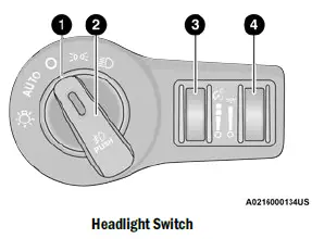
Headlight Switch
- Rotate Headlight Control
- Push Fog Light Control
- Instrument Panel Dimmer Control
- Ambient Light Dimmer Control
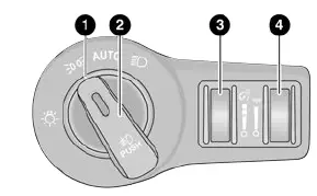
Headlight Switch (Vehicles Sold In Canada Only)
- Rotate Headlight Control
- Push Fog Light Control
- Instrument Panel Dimmer Control
- Ambient Light Dimmer Control
NOTE
Vehicles sold in Canada are equipped with a head-light switch without the OFF position. In order to turn the exterior lights off, the headlight switch must be rotated to AUTO position.
To turn on the headlights, rotate the headlight switch clockwise. When the headlight switch is on, the parking lights, taillights, license plate light and instrument panel lights are also turned on. To turn off the headlights, rotate the headlight switch back to the O (off) position.
NOTE
For vehicles sold in Canada, rotate the headlight switch clockwise from the parking lights and instrument panel lights position to the first detent to turn the headlight switch to the AUTO position. Rotate to the second detent to turn on headlights, parking lights, and instrument panel lights operation.
MULTIFUNCTION LEVER
The multifunction lever is located on the left side of the steering column.
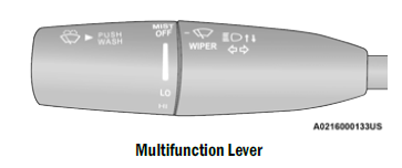
DAYTIME RUNNING LIGHTS (DRLS) — IF EQUIPPED
The Daytime Running Lights will turn on when the engine is started and will remain on unless the headlamps are turned to the on position, the parking brake is applied, or the ignition is placed in the OFF position.
NOTE
- For vehicles sold in Canada, the Daytime Running Lights will automatically deactivate when the front fog lights are turned on.
- If allowed by law in the country in which the vehicle was purchased, the Daytime Running Lights can be turned on and off using the Uconnect system Ú page 123.
On some vehicles, the Daytime Running Lights may deactivate, or reduce intensity, on one side of the vehicle (when a turn signal is activated on that side), or on both sides of the vehicle (when the hazard warning lights are activated).
HIGH/LOW BEAM SWITCH
Push the multifunction lever toward the instrument panel to switch the headlights to high beams. Pulling the multifunction lever back will turn the low beams on.
AUTOMATIC HIGH BEAM HEADLAMP CONTROL — IF EQUIPPED
The Automatic High Beam Headlamp Control system provides increased forward lighting at night by automating high beam control through the use of a camera mounted on the windshield. This camera detects vehicle specific light and automatically switches from high beams to low beams until the approaching vehicle is out of view.
NOTE
- The Automatic High Beam Headlamp Control can be turned on or off using the Uconnect system Ú page 123.
- Broken, muddy, or obstructed headlights and taillights of vehicles in the field of view will cause headlights to remain on longer (closer to the vehicle). Also, dirt, film, and other obstructions on the windshield or camera lens will cause the system to function improperly.
- To opt out of the Advanced Auto High-Beam Sensitivity Control and enter Reduced
High-Beam Sensitivity Control (not recommended), toggle the high beam lever six full on/off cycles within 10 seconds of placing the ignition in the ON position. The system will return to the default setting upon placing the ignition in the OFF position. - If the windshield or Automatic High Beam Head-lamp Control mirror is replaced, the mirror must be re-aimed to ensure proper performance. See a local authorized dealer.
FLASH-TO-PASS
You can signal another vehicle with your headlights by lightly pulling the multifunction lever toward you. This will cause the high beam headlights to turn on, and remain on, until the lever is released.
NOTE
If the multifunction lever is held in the flash-to pass position for more than 20 seconds, the high beams will shut off.
AUTOMATIC HEADLIGHTS
This system automatically turns the headlights on or off according to ambient light levels. To turn the system on, rotate the headlight switch counterclockwise to the AUTO position.
When the system is on, the Headlight Delay feature is also on. This means the headlights will stay on for up to 90 seconds after you place the ignition into the OFF position. To turn the automatic headlights off, turn the headlight switch out of the AUTO position.
NOTE
The engine must be running before the headlights will come on in the automatic mode.
PARKING LIGHTS
To turn on the parking lights and instrument panel lights, rotate the headlight switch clockwise. To turn off the parking lights, rotate the headlight switch back to the O (off) position.
NOTE
For vehicles sold in Canada, rotate the headlight switch to the AUTO position to turn off the parking lights.
AUTOMATIC HEADLIGHTS WITH WIPERS
If your vehicle is equipped with Automatic Headlights, it also has this customer-programmable feature. When your headlights are in the automatic mode and the engine is running, they will automatically turn on when the wiper system is on. This feature is programmable through the Uconnect system.
In addition, the headlights will turn off when the wipers are turned off if they were turned on by this feature.
HEADLIGHT TIME DELAY
To assist when exiting the vehicle, the headlight delay feature will leave the headlights on for up to 90 seconds. This delay is initiated when the ignition is placed in the OFF position while the headlight switch is on, and then the headlight switch is cycled off within 45 seconds. Headlight delay can be cancelled by either turning the headlight switch on then off, or by placing the ignition in the ON position.
NOTE
- This feature can be programmed through the Uconnect system Ú page 123.
- If you turn the headlights off before the ignition, they will turn off in the normal manner.
LIGHTS-ON REMINDER
If the headlights or parking lights are on after the ignition is placed in the OFF position, the vehicle will chime when the driver’s door is opened.
FOG LIGHTS — IF EQUIPPED
To activate the front fog lights, turn on the parking lights or the low beam headlights, and push the fog light button on the headlight switch.
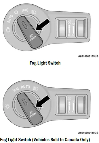
Fog Light Switch (Vehicles Sold In Canada Only)
The fog lights will operate only when the parking lights are on or when the vehicle headlights are on low beam. An indicator light located in the instrument cluster will illuminate when the fog lights are on. The fog lights will turn off when the switch is pushed a second time, when the headlight switch is rotated to the off position, or the high beam is selected.
TURN SIGNALS
Move the multifunction lever up or down to activate the turn signals. The arrows on each side of the instrument cluster flash to show proper operation.
NOTE
- If either light remains on and does not flash, or there is a very fast flash rate, check for a defective outside light bulb.
- A “Turn Signal On” message will appear in the instrument cluster display and a continuous chime will sound if the vehicle is driven more than 1 mile (1.6 km) with either turn signal on.
- LANE CHANGE ASSIST — IF EQUIPPED
Lightly push the multifunction lever up or down, without moving beyond the detent, and the turn signal will flash three times then automatically turn off.
INTERIOR LIGHTS
The interior lights come on when a door is opened.
To protect the battery, the interior lights will turn off automatically 10 minutes after the ignition is placed in the OFF position. This will occur if the interior lights were switched on manually or are on because a door is open. The Battery Protection also includes the glove compartment light and the trunk light. To restore interior light operation after automatic battery protection is enabled (lights off), either place the ignition in the ON/RUN position or cycle the light switch.
FRONT MAP/READING LIGHTS
These lights are mounted between the sun visors on the overhead console. Each light is turned on by pushing the lens. Push the lens a second time to turn off the light. These lights also turn on when a door is opened, when the unlock button on the remote keyless entry key fob is pushed, or when the dimmer control is turned fully upward, to the second detent.
Map/Reading Lights
AMBIENT LIGHT — IF EQUIPPED
The overhead console is equipped with an ambient light feature. This light casts illumination for improved visibility of the floor and center console area.
Rotate the right dimmer control upward or downward to increase or decrease the brightness of the door handle lights, map pocket lights, and ambient light located in the overhead console.
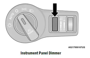
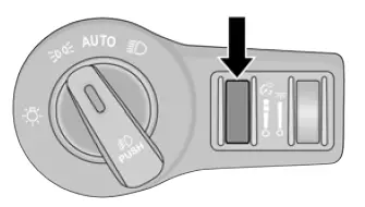
DIMMER CONTROLS
The dimmer control is part of the headlight switch and is located on the left side of the instrument panel.
With the parking lights or headlights on, rotating the left dimmer control upward will increase the brightness of the instrument panel lights and lighted cupholders (if equipped).
Instrument Panel Dimmer (Vehicles Sold In Canada Only)
Rotate the instrument panel dimmer control downward to the O (off) position, and the interior lights will remain off when the doors are open. Rotate the instrument panel dimmer control upward to the first detent to brighten all text displays such as the odometer, instrument cluster display, and radio when the parking lights or headlights are on. Rotating the instrument panel dimmer control completely upward to the second detent will turn on the interior lights. The interior lights will remain on when the dimmer control is in this position.
ILLUMINATED ENTRY
The courtesy lights will turn on when you use the key fob to unlock the doors or open any door. The lights will fade to off after approximately 30 seconds, or they will immediately fade to off once the ignition switch is placed in the ON/RUN position from the OFF position. The courtesy lights will not turn off if the instrument panel dimmer control is rotated upward to the second detent. The courtesy lights will turn off after 10 minutes when the ignition is placed in the OFF position to protect the battery. The illuminated entry system will not operate if the instrument panel dimmer control is rotated all the way down to the O (off) position.
WINDSHIELD WIPERS AND WASHERS
The windshield wiper/washer controls are located on the multifunction lever on the left side of the steering column. The multifunction lever operates the windshield wipers and washer when the ignition is placed in the ACC or ON/RUN position.
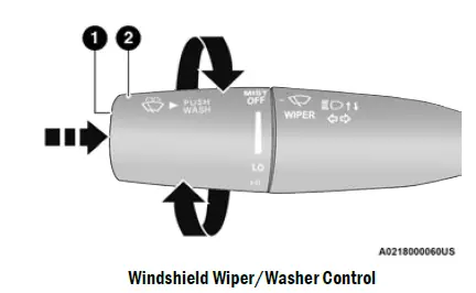
Windshield Wiper/Washer Control
- Push End Inward For Washer
- Rotate For Front Wiper Operation And Mist
WINDSHIELD WIPER OPERATION
Rotate the end of the multifunction lever to the first detent, past the intermittent settings for low-speed wiper operation, or to the second detent past the intermittent settings for high-speed wiper operation.
Intermittent Wipers
Rotate the end of the multifunction lever to the first detent position, and then turn the end of the lever to select the desired delay interval. There are four delay settings, which allow you to regulate the wipe interval from a minimum of one cycle every second to a maximum of approximately 36 seconds between cycles. The delay intervals will double in duration when the vehicle speed is 10 mph (16 km/h) or less.
Windshield Washers
To use the washer, push the multifunction lever inward (toward the steering wheel) and hold. If the lever is pushed while in the intermittent setting, the wipers will turn on and operate for two cycles after the end of the lever is released, and then resume the intermittent interval previously selected.
If the end of the lever is pushed while the wipers are in the off position, the wipers will operate for three wipe cycles and then turn off.
WARNING
Sudden loss of visibility through the windshield could lead to a collision. You might not see other vehicles or other obstacles. To avoid sudden icing of the windshield during freezing weather, warm the windshield with the defroster before and during windshield washer use.
Mist
Rotate the end of the lever downward to the MIST position and release for a single wiping cycle. The wipers will continue to operate until you release the multifunction lever
NOTE
The Mist feature does not activate the washer pump; therefore, no washer fluid will be sprayed on the windshield. The wash function must be used in order to spray the windshield with washer fluid. For information on wiper care and replacement, see Ú page 268.
CAUTION
- Turn the windshield wipers off when driving through an automatic car wash. Damage to the windshield wipers may result if the wiper control is left in any position other than off.
- In cold weather, always turn off the wiper switch and allow the wipers to return to the park position before turning off the engine. If the wiper switch is left on and the wipers freeze to the windshield, damage to the wiper motor may occur when the vehicle is restarted.
- Always remove any buildup of snow that prevents the windshield wiper blades from returning to the off position. If the windshield wiper control is turned off and the blades cannot return to the off position, damage to the wiper motor may occur.
RAIN SENSING WIPERS — IF EQUIPPED
This feature senses rain or snowfall on the windshield and automatically activates the wipers. Rotate the end of the multifunction lever to one of four settings to activate this feature.
The sensitivity of the system can be adjusted with the multifunction lever. Wiper delay position 1 is the least sensitive, and wiper delay position 4 is the most sensitive.
Wiper delay position three should be used for normal rain conditions.
NOTE
- The Rain Sensing feature will not operate when the wiper switch is in the low or high-speed position.
- The Rain Sensing feature may not function properly when ice, or dried salt water is present on the windshield.
- Use of Rain-X or products containing wax or silicone may reduce Rain Sensing performance.
- The Rain Sensing feature can be turned on and off using the Uconnect system Ú page 123.
The Rain Sensing system has protection features for the wiper blades and arms, and will not operate under the following conditions:
- Low Ambient Temperature
- When the ignition is first placed in the ON position, the Rain Sensing system will not operate until the wiper switch is moved, vehicle speed is greater than 0 mph (0 km/h), or the outside temperature is greater than 32°F (0°C).
- Transmission In NEUTRAL Position
When the ignition is ON, and the transmission is in the NEUTRAL position, the Rain Sensing system will not operate until the wiper switch is moved, vehicle speed is greater than 3 mph (5 km/h), or the gear selector is moved out of the NEUTRAL position. - Remote Start Mode Inhibit
On vehicles equipped with the Remote Start system, Rain Sensing wipers are not operational when the vehicle is in the Remote Start mode.
CLIMATE CONTROLS
The Climate Control system allows you to regulate the temperature, air flow, and direction of air circulating throughout the vehicle. The controls are located on the touchscreen (if equipped) and on the instrument panel below the radio.
AUTOMATIC CLIMATE CONTROL DESCRIPTIONS AND FUNCTIONS
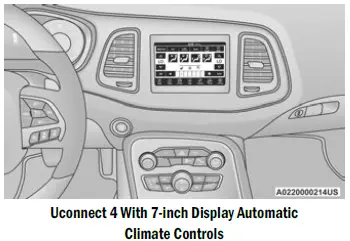
MAX A/C Button
 Press and release the MAX A/C button on the touchscreen to change the current setting to the coldest output of air. The MAX A/C indicator illuminates when MAX A/C is on. Pressing and releasing the button again will cause the MAX A/C operation to exit.
NOTE
The MAX A/C button is only available on the touch-screen.
A/C Button
 Press and release this button on the touchscreen, or push the button on the faceplate to change the current setting. The A/C indicator illuminates when A/C is ON.The Air Conditioning (A/C) button allows the operator to manually activate or deactivate the air conditioning system. When the air conditioning system is turned on, cool dehumidified air will flow through the outlets into the cabin.
NOTE
- If fog or mist appears on the windshield or side glass, select Defrost mode, and increase blower speed if needed.
- If your air conditioning performance seems lower than expected, check the front of the A/C condenser (located in front of the radiator), for an accumulation of dirt or insects. Clean with a gentle water spray from the front of the radiator and through the condenser.
- Recirculation Button
 Press and release this button on the touchscreen, or push the button on the faceplate to change the system between recirculation mode and outside air mode. The Recirculation indicator and the A/C indicator illuminate when the Recirculation button is pressed. Recirculation can be used when outside conditions such as smoke, odors, dust, or high humidity are present. Recirculation can be used in all modes. Recirculation may be unavailable (button on the touchscreen greyed out) if conditions exist that could create fogging on the inside of the windshield. The A/C can be deselected manually without disturbing the mode control selection. Continuous use of the Recirculation mode may make the inside air stuffy and window fogging may occur. Extended use of this mode is not recommended. Recirculation mode may automatically adjust to optimize customer experience for warming, cooling, dehumidification, etc. In cold weather, use of Recirculation mode may lead to excessive window fogging. The Recirculation feature may be unavailable if conditions exist that could create fogging on the inside of the windshield.
- AUTO Button
 Deselected manually without disturbing the mode control selection. Continuous use of the Recirculation mode may make the inside air stuffy and window fogging may occur. Extended use of this mode is not recommended. Recirculation mode may automatically adjust to optimize customer experience for warming, cooling, dehumidification, etc.
In cold weather, use of Recirculation mode may lead to excessive window fogging. The Recirculation feature may be unavailable if conditions exist that could create fogging on the inside of the windshield. AUTO Button and air distribution. Air Conditioning (A/C) may be active during AUTO operation to improve performance. AUTO mode is highly recommended for efficiency. You can press and release this button on the touchscreen, or push the button on the faceplate, to turn AUTO on. The AUTO indicator illuminates when AUTO is on. Toggling this function will cause the system to switch between manual mode and automatic modes Ú page 54.
Front Defrost Button
 Press and release the Front Defrost button on the touchscreen, or push and release the button on the faceplate, to change the current airflow setting to Defrost mode. The Front Defrost indicator illuminates when Front Defrost is on. Air comes from the windshield and side window demist outlets. When the defrost button is selected, the blower level may increase. Use Defrost mode with maximum temperature settings for best windshield and side window defrosting and defogging. When toggling the front defrost mode button, the climate system will return to the previous setting.
Rear Defrost Button
 Press and release the Rear Defrost button on the touchscreen, or push and release the button on the faceplate, to turn on the rear window defroster and the heated outside mirrors (if equipped). The Rear Defrost indicator illuminates when the rear window defroster is on. The rear window defroster automatically turns off after 10 minutes.
CAUTION
Failure to follow these cautions can cause damage to the heating elements:
- Use care when washing the inside of the rear window. Do not use abrasive window cleaners on the interior surface of the window. Use a soft cloth and a mild washing solution, wiping parallel to the heating elements. Labels can be peeled off after soaking with warm water.
- Do not use scrapers, sharp instruments, or abrasive window cleaners on the interior surface of the window.
- Keep all objects a safe distance from the window.
Driver And Passenger Up And Down Buttons
These buttons provide the driver and passenger with independent temperature control.
 Push the red button on the faceplate or touchscreen or press and slide the temperature bar towards the red arrow button on the touchscreen for warmer temperature settings.
 Push the blue button on the faceplate or touchscreen or press and slide the temperature bar towards the blue arrow on the touchscreen for cooler temperature settings.
- SYNC Button
Press the SYNC button on the touchscreen to toggle the Sync feature on/off. The SYNC indicator is illuminated when SYNC is on. SYNC is used to synchronize the passenger temperature setting with the driver temperature setting. Changing the passenger temperature setting while in SYNC will automatically exit this feature.
NOTE
The SYNC button is only available on the touch-screen.
Blower Control
 Blower Control is used to regulate the amount of air forced through the Climate Control system. There are seven blower speeds available. Adjusting the blower will cause automatic mode to switch to manual operation. The speeds can be selected using either the blower control knob on the faceplate or the buttons on the touchscreen.
Faceplate
The blower speed increases as you turn the blower control knob clockwise from the lowest blower setting. The blower speed decreases as you turn the blower control knob counterclockwise.
Touchscreen
Use the small blower icon to reduce the blower setting and the large blower icon to increase the blower setting. Blower can also be selected by pressing the blower bar area between the icons.
Mode Control
 Select Mode by pressing one of the Mode buttons on the touchscreen to change the airflow distribution mode. The airflow distribution mode can be adjusted so air comes from the instrument panel outlets, floor outlets, defrost outlets and demist outlets.
- Panel Mode
 Air comes from the outlets in the instrument panel. Each of these outlets can be individually adjusted to direct the flow of air. The air vanes of the center outlets and outboard outlets can be moved up and down or side to side to regulate airflow direction. There is a shut-off wheel located below the air vanes to shut off or adjust the amount of airflow from these outlets.
- Bi-Level Mode
Air comes from the instrument panel outlets and floor outlets. A slight amount of air is directed through the defrost and side window demister outlets. - NOTE
Bi-Level mode is designed under comfort conditions to provide cooler air out of the panel outlets and warmer air from the floor outlets. - Floor Mode
- Air comes from the floor outlets. A slight amount of air is directed through the defrost and side window demister outlets.
Mix Mode
 Air is directed through the floor, defrost, and side window demister outlets. This setting works best in cold or snowy conditions that require extra heat to the windshield. This setting is good for maintaining comfort while reducing moisture on the windshield.
Climate Control OFF Button
 Press and release this button to turn the Climate Control ON/OFF.
- AUTOMATIC TEMPERATURE CONTROL (ATC)
Automatic Operation - Push the AUTO button on the faceplate, or the AUTO button on the touchscreen on the Automatic Temperature Control (ATC) Panel.
- Next, adjust the temperature that you would like the system to maintain by adjusting the driver and passenger temperature control buttons. Once the desired temperature is displayed, the system will achieve and automatically maintain that comfort level.
- When the system is set up for your comfort level, it is not necessary to change the settings. You will experience the greatest efficiency by simply allowing the system to function automatically.
NOTE
- It is not necessary to move the temperature settings for cold or hot vehicles. The system automatically adjusts the temperature, mode, and blower speed to provide comfort as quickly as possible.
- The temperature can be displayed in US or Metric units within Uconnect Settings Ú page 123.
- To provide you with maximum comfort in the Automatic mode during cold start-ups, the blower fan will remain on low until the engine warms up. The blower will increase in speed and transition into Auto mode.
- Manual Operation Override
This system offers a full complement of manual override features. The AUTO symbol in the front ATC display will be turned off when the system is being used in the manual mode. - CLIMATE VOICE COMMANDS
Adjust vehicle temperatures hands-free and keep everyone comfortable while you keep moving ahead.
Push the VR button. After the beep, say one of the following commands: - “Set driver temperature to 70 degrees”
- “Set passenger temperature to 70 degrees”
TIP
Voice Command for Climate may only be used to adjust the interior temperature of your vehicle. Voice Command will not work to adjust the heated seats or steering wheel if equipped.
OPERATING TIPS
Refer to the chart at the end of this section for suggested control settings for various weather conditions.
Summer Operation
The engine cooling system must be protected with a high-quality antifreeze coolant to provide proper corrosion protection and to protect against engine overheating. OAT coolant (conforming to MS.90032) is recommended.
Winter Operation
To ensure the best possible heater and defroster performance, make sure the engine cooling system is functioning properly and the proper amount, type, and concentration of coolant is used. Use of the Air Recirculation mode during Winter months is not recommended, because it may cause window fogging.
Vacation/Storage
For information on maintaining the Climate Control system when the vehicle is being stored for an extended period of time, see Ú page 307.
- Window Fogging
Vehicle windows tend to fog on the inside in mild, rainy, and/or humid weather. To clear the windows, select Defrost or Mix mode and increase the front blower speed. Do not use the Recirculation mode without A/C for long periods, as fogging may occur. - Outside Air Intake
Make sure the air intake, located directly in front of the windshield, is free of obstructions, such as leaves. Leaves collected in the air intake may reduce airflow, and if they enter the air distribution box, they could plug the water drains. In Winter months, make sure the air intake is clear of ice, slush, and snow. - Cabin Air Filter
The Climate Control system filters out dust and pollen from the air. Contact an authorized dealer to service your cabin air filter, and to have it replaced when needed.
Operating Tips Chart
| WEATHER | CONTROL SETTINGS |
| Hot Weather And Vehicle Interior Is Very Hot | Set the mode control to (Panel Mode), (MAX A/C) on, and blower on high. Roll down the windows for a minute to flush out the hot air. Adjust the controls as needed to achieve comfort. |
| Warm Weather | Turn (A/C) on and set the mode control to (Panel Mode). |
| Cool Sunny | Operate in (Bi-Level Mode). |
| Cool & Humid Conditions | Set the mode control to (Mix Mode) and turn (A/C) on to keep windows clear. |
| Cold Weather | Set the mode control to (Floor Mode). If windshield fogging starts to occur, move the control to (Mix Mode). |
INTERIOR STORAGE AND EQUIPMENT
STORAGE
Glove Compartment
The glove compartment is located on the passenger side of the instrument panel.
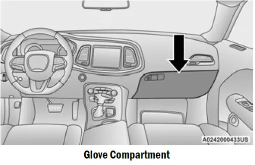
- Glove Compartment
To open the glove compartment, pull the release handle.
Console Features
The center console has a storage compartment located underneath the armrest. The compartment contains a 12 Volt power outlet, and is also equipped with a USB port featuring active charging, which will continue charging your device up to 60 minutes after the ignition is turned off. The USB port also may be equipped with an IPOD®/USB control Ú page 57, or Apple Car Play® and Android Auto™ Ú page 167.
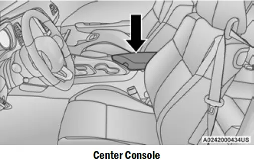
- WARNING
- Do not operate this vehicle with a console compartment lid in the open position. Driving with the console compartment lid open may result in injury in a collision.
- ILLUMINATED CUPHOLDERS — IF EQUIPPED
The front cupholders are equipped with a light ring that illuminates the cupholders for the front passengers. The light ring is controlled by the dimmer control Ú page 49. 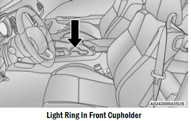
- Light Ring In Front Cupholder
USB/AUX CONTROL
Located in the front storage area of the center console, this feature allows an external USB device to be connected to the audio system. Plugging in a smartphone device to a USB port may activate Android Auto™ or Apple Car Play® features, if equipped 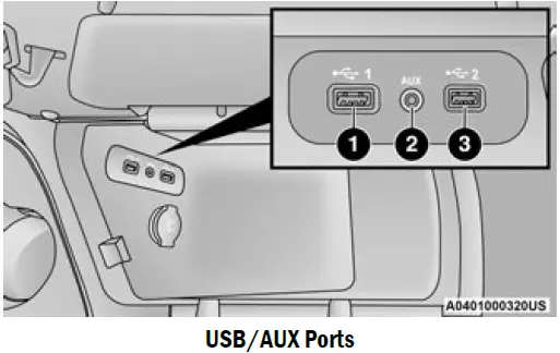
- USB 1 Port
- AUX Jack
- USB 2 Port
NOTE
Charge unsupported devices with the Charge Only USB ports. If an unsupported device is plugged into a Media USB port, a message will display on the touchscreen that the device is not supported by the system
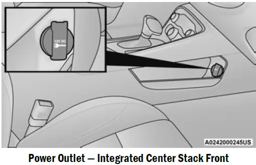
- ELECTRICAL POWER OUTLETS
Your vehicle is equipped with 12 Volt (13 Amp) power outlets that can be used to power cellular phones, small electronics and other low powered electrical accessories. The power outlets are labeled with either a “key” or a “battery” symbol to indicate how the outlet is powered. Power outlets labeled with a key symbol can be powered when the ignition is in the ACC or ON/RUN position, while the outlets labeled with a battery symbol are connected directly to the battery and powered at all times. These power outlets can also operate a conventional cigar lighter unit. The front power outlet is located next to the storage area on the integrated center stack of the instrument panel. 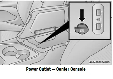
- NOTE
The front integrated center stack power outlet can be changed from switched ignition to constant battery powered by moving the integrated center stack fuse #12 in the Rear Power Distribution Center from fuse location “IGN” to “B+” In addition to the front center stack power outlet, there is also a power outlet located in the center console to the left of the media hub. 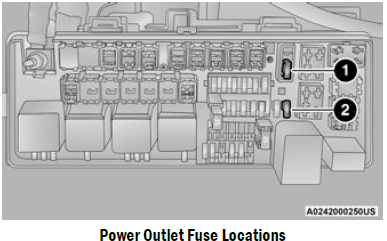
- NOTE
All accessories connected to these powered outlets should be removed or turned off when the vehicle is not in use to protect the battery against discharge.
Power Outlet Fuse Locations
- Fuse 20A Yellow Power Outlet Integrated Center Stack
Fuse 20A Yellow Power Outlet Center Console.
WARNING
To avoid serious injury or death:
- Only devices designed for use in this type of outlet should be inserted into any 12 Volt outlet.
- Do not touch with wet hands.
Close the lid when not in use and while driving the vehicle. - If this outlet is mishandled, it may cause an electric shock and failure.
CAUTION
- Do not exceed the maximum power of 160 Watts (13 Amps) at 12 Volts. If the 160 Watt (13 Amp) power rating is exceeded the fuse protecting the system will need to be replaced.
- Power outlets are designed for accessory plugs only. Do not insert any other object in the power outlets as this will damage the outlet and blow the fuse. Improper use of the power outlet can cause damage not covered by your New Vehicle Limited Warranty.
- Many accessories that can be plugged in draw power from the vehicle’s battery, even when not in use (i.e., cellular phones, etc.). Eventually, if plugged in long enough, the vehicle’s battery will discharge sufficiently to degrade battery life and/or prevent the engine from starting.
Accessories that draw higher power (i.e., coolers, vacuum cleaners, lights, etc.), will degrade the battery even more quickly. Only use these intermittently and with greater caution.
After the use of high power draw accessories, or long periods of the vehicle not being started (with accessories still plugged in), the vehicle must be driven a sufficient length of time to allow the alternator to recharge the vehicle’s battery.
Power outlets are designed for accessory plugs only. Do not hang any type of accessory or accessory bracket from the plug. Improper use of the power outlet can cause damage.
WINDOWS
POWER WINDOW CONTROLS
The window switches on the driver’s door control all the door windows.
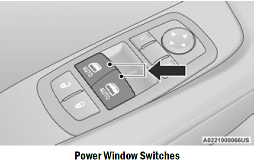
- Power Window Switches
The passenger door window can also be operated by using the single window controls on the passenger door trim panel. The window controls will operate only when the ignition is in the ACC or ON/RUN position. - NOTE
The power window switches will remain active for up to 10 minutes after the ignition is placed in the OFF position. Opening either front door will cancel this feature. The timing is programmable within Uconnect Settings Ú page 123.
WARNING
Never leave children unattended in a vehicle, and do not let children play with power windows. Do not leave the key fob in or near the vehicle, or in a location accessible to children, and do not leave the ignition of a vehicle equipped with Keyless Enter ‘n Go™ in the ACC or ON/RUN position. Occupants, particularly unattended children, can become entrapped by the windows while operating the power window switches. Such entrapment may result in serious injury or death.
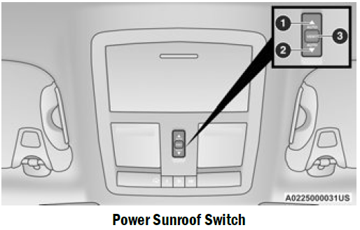
- WARNING
- Never leave children unattended in a vehicle, or with access to an unlocked vehicle. Never leave the key fob in or near the vehicle, or in a location accessible to children. Do not leave the ignition of a vehicle equipped with Keyless Enter ‘n Go™ in the ACC or ON/RUN position. Occupants, particularly unattended children, can become entrapped by the power sunroof while operating the power sunroof switch. Such entrapment may result in serious injury or death.
- In a collision, there is a greater risk of being thrown from a vehicle with an open sunroof. You could also be seriously injured or killed. Always fasten your seat belt properly and make sure all passengers are also properly secured.
- Do not allow small children to operate the sunroof. Never allow your fingers, other body parts, or any object, to project through the sunroof opening. Injury may result.
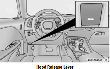
- OPENING AND CLOSING THE SUNROOF
Express Open/Close
Push the switch rearward and release it within one-half second, the sunroof and sunshade will open automatically and stop at full open position. Push the switch forward and release it within one-half second and the sunroof will close automatically from any position. During Express Open or Express Close operation, any other movement of the sunroof switch will stop the sunroof. - Manual Open/Close
Push and hold the switch rearward, the sunroof and sunshade will open and automatically stop at full open position. Push and hold the switch forward and the sunroof will close from any position and stop at a full closed position. Any release of the switch during open or close operation will stop the sunroof movement. The sunroof will remain in a partially opened position until the switch is operated and held again. - Venting The Sunroof
Push and release the Vent switch within one half second and the sunroof will open to the vent position. During Express Vent operation, any other actuation of the sunroof switches will stop the sunroof operation.
PINCH PROTECT FEATURE — IF EQUIPPED
- This feature will detect an obstruction in the closing of the sunroof during the Express Close operation. If an obstruction in the path of the sunroof is detected, the sunroof will automatically retract. Remove the obstruction if this occurs.
- NOTE
If three consecutive sunroof close attempts result in Pinch Protect reversals, Pinch Protect will disable and the sunroof must be closed in Manual Mode. - POWER SUNROOF — IF EQUIPPED
The power sunroof switch is located between the sun visors on the overhead console.
SUNSHADE OPERATION
The sunshade can be opened manually. However, the sunshade will open automatically as the sunroof opens.
NOTE
The sunshade cannot be closed if the sunroof is open.
SUNROOF MAINTENANCE
Use only a non-abrasive cleaner and a soft cloth to clean the glass panel. Periodically check for and clear out any debris that may have collected in the tracks.
IGNITION OFF OPERATION
NOTE
- The power sunroof switch can remain active in Accessory Delay for up to approximately
10 minutes after the vehicle’s ignition is placed to the OFF position. Opening either front door will cancel this feature. - This feature is programmable using the Uconnect system Ú page 123.
HOOD
OPENING THE HOOD
To open the hood, two latches must be released.
- Pull the release lever located underneath the driver’s side of the instrument panel.
- Reach under the hood, push the safety catch to the left and lift the hood.
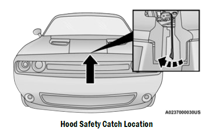
- Hood Safety Catch Location
CLOSING THE HOOD
In one continuous motion, pull down on the front edge of the hood with moderate force until the angle is below the crossover point (where the gas props are no longer resisting) and let the hood continue to fall closed from its own inertia. - WARNING
- Be sure the hood is fully latched before driving your vehicle. If the hood is not fully latched, it could open when the vehicle is in motion and block your vision. Failure to follow this warning could result in serious injury or death.
TRUNK
OPENING THE TRUNK
The trunk may be opened in several ways:
- Power trunk release button on the instrument panel
- Trunk button on the key fob
- Trunk Passive Entry button Ú page 24
- External release switch located on the under-side of the decklid overhang
NOTE
The release feature will function only when the vehicle is unlocked. With the ignition in the ON/RUN position, the trunk open symbol will display in the instrument cluster indicating that the trunk is open. The odometer display will reappear once the trunk is closed. With the ignition in the OFF position, the trunk open symbol will display until the trunk is closed.
Power Trunk Release Button
 The trunk can be opened from inside the vehicle using the power trunk release button located on the instrument panel to the left of the steering wheel.
- NOTE:
The automatic transmission must be in PARK before the button will operate. For manual trans-missions, the vehicle must be in NEUTRAL. - Key Fob Trunk Release Button
 Push the power trunk button on the key fob twice within five seconds to release the trunk.
- Passive Entry Button
Push the trunk Passive Entry button which is located on the back of the trunk lid. With a valid Passive Entry key fob within 5 ft (1.5 m) of the trunk, push the Passive Entry button to open the trunk. 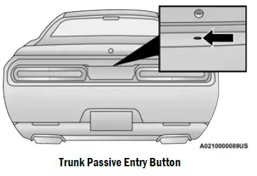
- CLOSING THE TRUNK
With one or more hands placed on the outside trunk surface push the trunk lid down until you hear the trunk lock latch into place. - NOTE:
Before closing the trunk lid, make sure your key fob is not inside the trunk area. The trunk will latch then automatically unlock if the key fob is detected, not allowing the key fob to be locked in the trunk area. - TRUNK SAFETY
Trunk Emergency Release
As a security measure, a trunk internal emergency release lever is built into the trunk latching mechanism. In the event of an individual being locked inside the trunk, the trunk can be opened by actuating the glow-in-the-dark handle attached to the trunk latching mechanism.
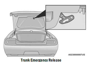
WARNING
Do not allow children to have access to the trunk, either by climbing into the trunk from outside, or through the inside of the vehicle. Always close the trunk lid when your vehicle is unattended. Once in the trunk, young children may not be able to escape, even if they entered through the rear seat. If trapped in the trunk, children can die from suffocation or heat stroke.
Reference Links
View Full PDF: Dodge Challenger 2022 User Manual | Auto User Guide
Download Link: Owner’s Manuals & User Guides | Dodge