Dodge Challenger 2023 Servicing and Maintenance User Manual
Servicing and Maintenance
SCHEDULED SERVICING
3.6L AND 5.7L ENGINES
These engines are equipped with an automatic oil change indicator system. The oil change indicator system will remind you that it is time to take your vehicle in for scheduled maintenance.
Based on engine operation conditions, the oil change indicator message will illuminate. This means that service is required for the vehicle. Operating conditions such as frequent short-trips, trailer tow, and extremely hot or cold ambient temperatures will influence when the “Change Oil” or “Oil Change Required” message is displayed. Have your vehicle serviced as soon as possible, within the next 500 miles (805 km).
The “Oil Change Required” message will be displayed in the instrument cluster and a single chime will sound, indicating that an oil change is necessary.
An authorized dealer will reset the oil change indicator message after completing the scheduled oil change.
NOTE:
Under no circumstances should oil change intervals exceed 10,000 miles (16,000 km), 12 months or 350 hours of engine run time, whichever comes first. The 350 hours of engine run or idle time is generally only a concern for fleet customers.
Once A Month Or Before A Long Trip:
- Check engine oil level.
- Check windshield washer fluid level.
- Check tire pressure and look for unusual wear or damage. Rotate tires at the first sign of irregular wear, even if it occurs before your next scheduled service.
- Check the fluid levels of the coolant reservoir, brake master cylinder, and power steering (if equipped) and fill as needed.
- Check function of all interior and exterior lights.
Maintenance Plan — 3.6L And 5.7L
Refer to the maintenance chart for the required maintenance intervals.
| At Every Oil Change Interval As Indicated By Oil Change Indicator System: |
| Change oil and filter. |
| Rotate the tires at the first sign of irregular wear, even if it occurs before your next scheduled service. |
| Inspect battery and clean and tighten terminals as required. |
| Inspect the CV/Universal joints. |
| Inspect brake pads, shoes, rotors, drums, hoses and parking brake. |
| Inspect engine cooling system protection and hoses. |
| Inspect exhaust system. |
| Inspect engine air cleaner filter if using in dusty or off-road conditions, replace engine air cleaner filter if necessary. |
| Mileage or time passed (whichever comes first) | 20,000 | 30,000 | 40,000 | 50,000 | 60,000 | 70,000 | 80,000 | 90,000 | 100,000 | 110,000 | 120,000 | 130,000 | 140,000 | 150,000 |
| Or Years: | 2 | 3 | 4 | 5 | 6 | 7 | 8 | 9 | 10 | 11 | 12 | 13 | 14 | 15 |
| Or Kilometers: | 32,000 | 48,000 | 64,000 | 80,000 | 96,000 | 112,000 | 128,000 | 144,000 | 160,000 | 176,000 | 192,000 | 208,000 | 224,000 | 240,000 |
| Additional Inspections | ||||||||||||||
| Inspect the CV/Universal joints. | X | X | X | X | X | X | X | X | X | X | X | X | X | X |
| Inspect front suspension, tie rod ends, boot seals and replace if necessary. | X | X | X | X | X | X | X | |||||||
| Inspect the rear axle fluid. Inspect the front axle fluid (All Wheel Drive Only). | X | X | X | X | X | X | X | |||||||
| Inspect the manual transmission fluid (if equipped). | X | X | X | X | X | X | X | |||||||
| Inspect the brake linings, replace as necessary. | X | X | X | X | X | X | X | |||||||
| Adjust parking brake on vehicles equipped with four wheel disc brakes. | X | X | X | X | X | X | X | |||||||
| Inspect transfer case fluid (All Wheel Drive Only). | X | X | X | X | X | |||||||||
| Additional Maintenance | ||||||||||||||
| Replace engine air cleaner filter. | X | X | X | X | X | |||||||||
| Replace cabin air filter. | To be replaced every 12,000 mi (19,000 km). | |||||||||||||
| Mileage or time passed (whichever comes first) | 20,000 | 30,000 | 40,000 | 50,000 | 60,000 | 70,000 | 80,000 | 90,000 | 100,000 | 110,000 | 120,000 | 130,000 | 140,000 | 150,000 |
| Or Years: | 2 | 3 | 4 | 5 | 6 | 7 | 8 | 9 | 10 | 11 | 12 | 13 | 14 | 15 |
| Or Kilometers: | 32,000 | 48,000 | 64,000 | 80,000 | 96,000 | 112,000 | 128,000 | 144,000 | 160,000 | 176,000 | 192,000 | 208,000 | 224,000 | 240,000 |
| Replace spark plugs.1 | X | |||||||||||||
| Flush and replace the engine coolant at 10 years or 150,000 miles (240,000 km) whichever comes first. | X | X | ||||||||||||
| Change the manual transmission fluid (if equipped) if using your vehicle for any of the following: Most of your driving is at sustained speeds during hot weather, above 90°F (32°C), driving in dusty conditions, or stop and go driving. | X | X | X | |||||||||||
| Change the transfer case fluid; if using your vehicle for any of the following: police, taxi, fleet, off-road, or frequent trailer towing. (All Wheel Drive Only). | X | X |
| Mileage or time passed (whichever comes first) | 20,000 | 30,000 | 40,000 | 50,000 | 60,000 | 70,000 | 80,000 | 90,000 | 100,000 | 110,000 | 120,000 | 130,000 | 140,000 | 150,000 |
| Or Years: | 2 | 3 | 4 | 5 | 6 | 7 | 8 | 9 | 10 | 11 | 12 | 13 | 14 | 15 |
| Or Kilometers: | 32,000 | 48,000 | 64,000 | 80,000 | 96,000 | 112,000 | 128,000 | 144,000 | 160,000 | 176,000 | 192,000 | 208,000 | 24,000 | 240,000 |
| Change the rear axle fluid and on models equipped with All Wheel Drive (AWD) change the front axle fluid if using your vehicle for any of the following: police, taxi, fleet, off-road, or frequent trailer towing. | X | X | X | |||||||||||
| Inspect and replace PCV valve if necessary. | X |
- The spark plug change interval is mileage based only, yearly intervals do not apply.
WARNING!
- You can be badly injured working on or around a motor vehicle. Do only service work for which you have the knowledge and the right equipment. If you have any doubt about your ability to perform a service job, take your vehicle to a competent mechanic.
- Failure to properly inspect and maintain your vehicle could result in a component malfunction and effect vehicle handling and performance. This could cause an accident.
ENGINE COMPARTMENT
3.6L ENGINE
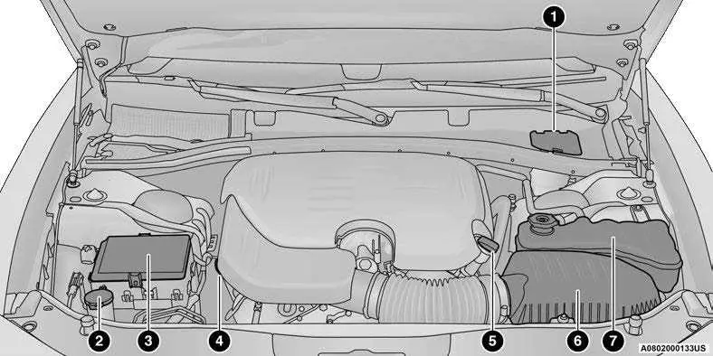
- Brake Fluid Reservoir Access Cover
- Washer Fluid Reservoir Cap
- Power Distribution Center (Fuses)
- Engine Oil Dipstick
- Engine Oil Fill
- Engine Air Cleaner Filter
- Engine Coolant Pressure Reservoir
5.7L ENGINE
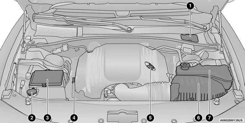
- Brake Fluid Reservoir Access Cover
- Washer Fluid Reservoir Cap
- Power Distribution Center (Fuses)
- Engine Oil Dipstick
- Engine Oil Fill
- Engine Air Cleaner Filter
- Engine Coolant Pressure Reservoir
CHECKING OIL LEVEL
WARNING!
- Never smoke while working in the engine compartment: gas and inflammable vapors may be present, with the risk of fire.
- Be very careful when working in the engine compartment when the engine is hot: you may get burned. Do not get too close to the radiator cooling fan: the electric fan may start; danger of injury. Scarves, ties and other loose clothing might be pulled by moving parts.
CAUTION!
- Be careful not to confuse the various types of fluids while topping up: they are not compatible with each other! Topping up with an unsuitable fluid could severely damage your car.
- The oil level must never exceed the MAX mark.
- Always top up using engine oil of the same specifications as what is already in the engine.
- If the engine oil is being topped up, wait for the engine to cool down before loosening the filler cap, particularly for vehicles with aluminum cap (if equipped). WARNING: risk of burns!
Overfilling or underfilling the crankcase will cause aeration or loss of oil pressure. This could damage your engine.
To ensure proper engine lubrication, the engine oil must be maintained at the correct level. Check the oil level at regular intervals, such as every fuel stop. The best time to check the engine oil level is about ten minutes after a fully warmed up engine is shut off.
Checking the oil while the vehicle is on level ground will improve the accuracy of the oil level readings.
There are four possible dipstick types:
- Crosshatched zone.
- Crosshatched zone marked SAFE.
- Crosshatched zone marked with MIN at the low end of the range and MAX at the high end of the range.
- Crosshatched zone marked with dimples at the MIN and the MAX ends of the range.
NOTE:
Always maintain the oil level within the crosshatch markings on the dipstick.
Adding 1 quart (1 liter) of oil when the reading is at the low end of the dipstick range will raise the oil level to the high end of the range marking.
CAUTION!
Overfilling or underfilling the crankcase will cause aeration or loss of oil pressure. This could damage your engine.
ADDING WASHER FLUID
The windshield washer fluid reservoir is located in the front of the engine compartment. Be sure to check the fluid level at regular intervals. Fill the reservoir with windshield washer solvent (not radiator antifreeze) and operate the system for a few seconds to flush out the residual water.
When refilling the washer fluid reservoir, apply some washer fluid to a cloth or towel and wipe the wiper blades clean. This will help blade performance.
To prevent freeze-up of your windshield washer system in cold weather, select a solution or mixture that meets or exceeds the temperature range of your climate. This rating information can be found on most washer fluid containers.
The fluid reservoir will hold nearly 1 Gallon (4 Liters) of washer fluid when the message “Low Washer Fluid” appears in the instrument cluster.
WARNING!
Commercially available windshield washer solvents are flammable. They could ignite and burn you. Care must be exercised when filling or working around the washer solution.
MAINTENANCE-FREE BATTERY
Your vehicle is equipped with a maintenance-free battery. Water will never have to be added, and periodic maintenance is not required.
NOTE:
The battery is stored under an access cover in the trunk. Remote battery terminals are located in the engine compartment for jump starting page 216.
WARNING!
- Battery fluid is a corrosive acid solution and can burn or even blind you. Do not allow battery fluid to contact your eyes, skin, or clothing. Do not lean over a battery when attaching clamps. If acid splashes in eyes or on skin, flush the area immediately with large amounts of water Ú page 216.
- Battery gas is flammable and explosive. Keep flame or sparks away from the battery. Do not use a booster battery or any other booster source with an output greater than 12 Volts. Do not allow cable clamps to touch each other.
- Battery posts, terminals, and related accessories contain lead and lead compounds. Wash hands after handling.
- The battery in this vehicle has a vent hose that should not be disconnected and should only be replaced with a battery of the same type (vented).
CAUTION!
- It is essential when replacing the cables on the battery that the positive cable is attached to the positive post and the negative cable is attached to the negative post. Battery posts are marked positive (+) and negative (-) and are identified on the battery case. Cable clamps should be tight on the terminal posts and free of corrosion.
- If a “fast charger” is used while the battery is in the vehicle, disconnect both vehicle battery cables before connecting the charger to the battery. Do not use a “fast charger” to provide starting voltage.
PRESSURE WASHING
Cleaning the engine compartment with a high pressure washer is not recommended.
CAUTION!
Precautions have been taken to safeguard all parts and connections however, the pressures generated by these machines is such that complete protection against water ingress cannot be guaranteed.
VEHICLE MAINTENANCE
An authorized dealer has the qualified service personnel, special tools, and equipment to perform all service operations in an expert manner. Service Manuals are available which include detailed service information for your vehicle. Refer to these Service Manuals before attempting any procedure yourself.
NOTE:
Intentional tampering with emissions control systems may void your warranty and could result in civil penalties being assessed against you.
WARNING!
You can be badly injured working on or around a motor vehicle. Only do service work for which you have the knowledge and the proper equipment. If you have any doubt about your ability to perform a service job, take your vehicle to a competent mechanic.
ENGINE OIL
Engine Oil Selection
Use only the manufacturer’s recommended fluids page 278.
NOTE:
Hemi engines at times can tick right after startup and then quiet down after approximately 30 seconds. This is normal and will not harm the engine. This characteristic can be caused by short drive cycles: for example, if the vehicle is started then shut off after driving a short distance. Upon restarting, you may experience a ticking sound. Other causes could be if the vehicle is unused for an extended period of time, incorrect oil, extended oil changes or extended idling. If the engine continues to tick or if the Malfunction Indicator Light (MIL) comes on, see the nearest authorized dealer.
American Petroleum Institute (API)
Approved Engine Oil
These symbols mean that the oil has been certified by the API. The manufacturer only recommends API trademark oils.
- The API Starburst trademark certifies 0W-20, 0W-30 and 5W-30 engine oils.
The API Donut trademark certifies 0W-40 and 5W-40 engine oil.
CAUTION!
Do not use chemical flushes in your engine oil as the chemicals can damage your engine. Such damage is not covered by the New Vehicle Limited Warranty.
Synthetic Engine Oils
Your engine was designed for synthetic engine oils, only use synthetic API approved engine oils.
Synthetic engine oils which do not have both the correct API trademark and the correct SAE viscosity grade numbers should not be used.
Shaker Hood — If Equipped
Shaker Hood Oil Filler
For vehicles equipped with a “Shaker Hood”, the upper scoop will need to be removed so that oil can be properly added to the engine.
To do this, you will need follow the procedure below:
- Remove the four nuts with the Shaker tool located in glove compartment.
- Lift off the upper scoop.
NOTE:
Be sure to clean off all debris around or inside for the Shaker assembly. - Locate the oil fill cover in base assembly to expose the oil fill cap.
- Remove oil fill cap to add oil.
- Re-install Shaker assembly.
Shaker Hood Air Filter Cleaning
Shaker air filters are made of a unique, washable synthetic material. Base program air filters with paper media cannot be washed. All filters follow the same service interval, though Shaker systems substitute a cleaning while paper air filter elements are to be replaced.
- Remove the air filter from the intake and set the filter clamp aside.
- Measure the length of the filter media.
- Fill a bucket with warm clean water to the depth matching the filter media measurement and add a mild household detergent or air filter cleaning solution.
NOTE:
Never use strong detergents, high pressure, or gasoline on air filters. - Without allowing the solution to flow back into the inside of the air filter, submerge the filter media into the water and let it soak for ten minutes.
- Empty the bucket filled with dirty water and repeat steps 3 and 4.
- Refill the bucket with clean warm water and rinse the filter by rotating the filter.
NOTE:
The water should be clean with no signs of dirt in the bucket. - Allow the filter to air dry. Reinstall the filter on the intake system once it is dry.
NOTE:
Do not use forced air pressure to dry the air filter as damage may occur and void the warranty.
Shaker Hood Removal And Cleaning
- Remove the four nuts with the Shaker tool located in the glove compartment.
- Lift off the upper scoop.
NOTE:
Be sure to clean off all debris around or inside of the Shaker assembly. - Using a water and mild detergent clean the following locations:
- The water drain slot located at the front forward edge of the Shaker assembly.
- The seals attached to the scoop and air box.
- Lower water drains located in the lower Shaker assembly and air box as well as the hood interface areas for the seals. Apply Mopar® Leather, Rubber & Vinyl Protectant after cleaning to seals.
- Reinstall Shaker assembly.
Materials Added To Engine Oil
The manufacturer strongly recommends against the addition of any additives (other than leak detection dyes) to the engine oil. Engine oil is an engineered product and its performance may be impaired by supplemental additives.
Disposing Of Used Engine Oil And Oil
Filters
Care should be taken in disposing of used engine oil and oil filters from your vehicle. Used oil and oil filters, indiscriminately discarded, can present a problem to the environment. Contact an authorized dealer, service station or governmental agency for advice on how and where used oil and oil filters can be safely discarded in your area.
ENGINE OIL FILTER
The engine oil filter should be replaced with a new filter at every engine oil change.
Engine Oil Filter Selection
A full-flow type disposable oil filter should be used for replacement. The quality of replacement filters varies considerably. Only high quality Mopar® certified filters should be used.
ENGINE AIR CLEANER FILTER
For the proper maintenance intervals page 224.
NOTE:
Be sure to follow the “Severe Duty Conditions” maintenance interval if applicable.
WARNING!
The air induction system (air cleaner, hoses, etc.) can provide a measure of protection in the case of engine backfire. Do not remove the air induction system (air cleaner, hoses, etc.) unless such removal is necessary for repair or maintenance. Make sure that no one is near the engine compartment before starting the vehicle with the air induction system (air cleaner, hoses, etc.) removed. Failure to do so can result in serious personal injury.
Engine Air Cleaner Filter Selection
The quality of replacement filters varies considerably. Only high quality Mopar® certified filters should be used.
T/A Air Filter Maintenance — If Equipped
Clean Engine Air Filter
T/A air filters are made of a unique, washable material. Follow the recommended service interval as for non-T/A air filters, substituting a cleaning for replacement. Cleaning your engine air filter with the recommended Mopar® Performance Air Filter Service Kit is not required if you can still see any part of the wire screen on the entire air filter regardless of how dirty it may appear. When any part of the wire screen is no longer visible on the air filter, that is an indication it is time to clean the air filter.
For cleaning instructions see steps 1-7 from the Shaker Hood Air Filter Cleaning section page 232.
Unique for T/A, using the Mopar® Performance Air Filter Service Kit, spray oil evenly along the crown of each filter pleat holding the nozzle about 3 inches (76 mm) away from the air filter. One spray per 2 square inches (1,290 square mm) of air filter. With one complete coat of oil, let it wick (saturate) for about 20 minutes, and if required touch up any light areas on either side of the filter.
AIR CONDITIONER MAINTENANCE
For best possible performance, your air conditioner should be checked and serviced by an authorized dealer at the start of each warm season. This service should include cleaning of the condenser fins and a performance test. Drive belt tension should also be checked at this time.
WARNING!
- Use only refrigerants and compressor lubricants approved by the manufacturer for your air conditioning system. Some unapproved refrigerants are flammable and can explode, injuring you. Other unapproved refrigerants or lubricants can cause the system to fail, requiring costly repairs. Refer to Warranty Information Book, for further warranty information.
- The air conditioning system contains refrigerant under high pressure. To avoid risk of personal injury or damage to the system, adding refrigerant or any repair requiring lines to be disconnected should be done by an experienced technician.
CAUTION!
Do not use chemical flushes in your air conditioning system as the chemicals can damage your air conditioning components. Such damage is not covered by the New Vehicle Limited Warranty.
Refrigerant Recovery And Recycling
R-134a — If Equipped
R-134a Air Conditioning Refrigerant is a hydrofluo-rocarbon (HFC) that is an ozone-friendly substance. The manufacturer recommends that air conditioning service be performed by an authorized dealer or other service facilities using recovery and recycling equipment.
NOTE:
Use only manufacturer approved A/C system PAG compressor oil and refrigerants.
Refrigerant Recovery And Recycling
R-1234yf — If Equipped
R–1234yf Air Conditioning Refrigerant is a hydrofluoroolefin (HFO) that is endorsed by the Environmental Protection Agency and is an ozone-friendly substance with a low global-warming potential.
The manufacturer recommends that air conditioning service be performed by an authorized dealer using recovery and recycling equipment.
NOTE:
Use only manufacturer approved A/C system PAG compressor oil, and refrigerants.
Cabin Air Filter
The filter is located in the fresh air inlet under the hood, behind a removable panel in the cowl on the passenger side of the vehicle, next to the windshield wipers. When installing a new filter, ensure its proper orientation.
- Remove the access door in the cowl screen by pressing the retaining clips.
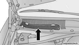
- Unsnap both ends and lift the filter access cover.
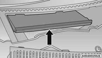 Filter Access Cover
 - Remove the used filter.
- Install the new filter with arrows pointing in the direction of airflow, which is toward the rear of the vehicle (text and arrows on the filter will indicate this).
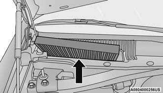 Cabin Air Filter
 - Close the filter access cover.
For the proper maintenance intervals page 254.
ACCESSORY DRIVE BELT INSPECTION
WARNING!
- Do not attempt to inspect an accessory drive belt with vehicle running.
- When working near the radiator cooling fan, disconnect the fan motor lead. The fan is temperature controlled and can start at any time regardless of ignition mode. You could be injured by the moving fan blades.
- You can be badly injured working on or around a motor vehicle. Only do service work for which you have the knowledge and the proper equipment. If you have any doubt about your ability to perform a service job, take your vehicle to a competent mechanic.
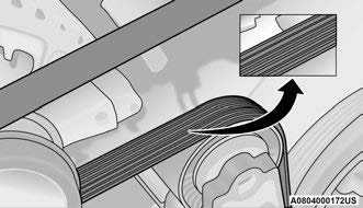
When inspecting accessory drive belts, small cracks that run across ribbed surface of belt from rib to rib, are considered normal. These are not a reason to replace belt. However, cracks running along a rib (not across) are not normal. Any belt with cracks running along a rib must be replaced. Also have the belt replaced if it has excessive wear, frayed cords or severe glazing.
Accessory Belt (Serpentine Belt)
Conditions that would require replacement:
- Rib chunking (one or more ribs has separated from belt body)
- Rib or belt wear
- Longitudinal belt cracking (cracks between two ribs)
- Belt slips
- “Groove jumping” (belt does not maintain correct position on pulley)
- Belt broken (note: identify and correct problem before new belt is installed)
- Noise (objectionable squeal, squeak, or rumble is heard or felt while drive belt is in operation)
Some conditions can be caused by a faulty component such as a belt pulley. Belt pulleys should be carefully inspected for damage and proper alignment.
Belt replacement on some models requires the use of special tools, we recommend having your vehicle serviced at an authorized dealer.
BODY LUBRICATION
Locks and all body pivot points, including such items as seat tracks, door hinge pivot points and rollers, liftgate, tailgate, decklid, sliding doors and hood hinges, should be lubricated periodically with a lithium-based grease, such as Mopar® Spray White Lube to ensure quiet, easy operation and to protect against rust and wear. Prior to the application of any lubricant, the parts concerned should be wiped clean to remove dust and grit; after lubricating, excess oil and grease should be removed. Particular attention should also be given to hood latching components to ensure proper function. When performing other underhood services, the hood latch, release mechanism and safety catch should be cleaned and lubricated.
The external lock cylinders should be lubricated twice a year, preferably in the Autumn and Spring. Apply a small amount of a high quality lubricant, such as Mopar® Lock Cylinder Lubricant directly into the lock cylinder.
WINDSHIELD WIPER BLADES
Clean the rubber edges of the wiper blades and the windshield periodically with a sponge or soft cloth and a mild nonabrasive cleaner. This will remove accumulations of salt or road film.
Operation of the wipers on dry glass for long periods may cause deterioration of the wiper blades. Always use washer fluid when using the wipers to remove salt or dirt from a dry windshield.
Avoid using the wiper blades to remove frost or ice from the windshield. Keep the blade rubber out of contact with petroleum products such as engine oil, gasoline, etc.
NOTE:
Life expectancy of wiper blades varies depending on geographical area and frequency of use. Poor performance of blades may be present with chattering, marks, water lines or wet spots. If any of these conditions are present, clean the wiper blades or replace as necessary.
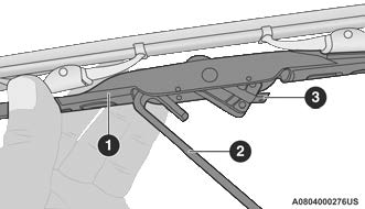
Wiper Blade Removal/Installation
CAUTION!
Do not allow the wiper arm to spring back against the glass without the wiper blade in place or the glass may be damaged.
- Lift the wiper arm to raise the wiper blade off of the glass, until the wiper arm is in the full up position.
- To disengage the wiper blade from the wiper arm, press the release tab on the wiper blade and while holding the wiper arm with one hand, slide the wiper blade down towards the base of the wiper arm.
Wiper Blade With Release Tab In Unlocked Position- Wiper Blade
- Wiper Arm
- Release Tab
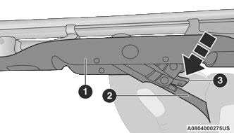
- With the wiper blade disengaged, remove the wiper blade from the wiper arm.
Wiper Blade Removed From Wiper Arm- Wiper Blade
- Wiper Arm
- Release Tab
- Gently lower the wiper arm onto the glass.
Installing The Front Wipers
- Lift the wiper arm off of the glass, until the wiper arm is in the full up position.
- Position the wiper blade near the hook on the tip of the wiper arm.
- Insert the hook on the tip of the arm through the opening in the wiper blade.
- Slide the wiper blade up into the hook on the wiper arm, latch engagement will be accompanied by an audible click.
- Gently lower the wiper blade onto the glass.
EXHAUST SYSTEM
The best protection against carbon monoxide entry into the vehicle body is a properly maintained engine exhaust system.
If you notice a change in the sound of the exhaust system; or if the exhaust fumes can be detected inside the vehicle; or when the underside or rear of the vehicle is damaged; have an authorized technician inspect the complete exhaust system and adjacent body areas for broken, damaged, deteriorated, or mispositioned parts. Open seams or loose connections could permit exhaust fumes to seep into the passenger compartment. In addition, have the exhaust system inspected each time the vehicle is raised for lubrication or oil change. Replace as required.
WARNING!
- Exhaust gases can injure or kill. They contain carbon monoxide (CO), which is colorless and odorless. Breathing it can make you unconscious and can eventually poison you. To avoid breathing CO, Ú page 196.
- A hot exhaust system can start a fire if you park over materials that can burn. Such materials might be grass or leaves coming into contact with your exhaust system. Do not park or operate your vehicle in areas where your exhaust system can contact anything that can burn.
CAUTION!
- The catalytic converter requires the use of unleaded fuel only. Leaded gasoline will destroy the effectiveness of the catalyst as an emissions control device and may seriously reduce engine performance and cause serious damage to the engine.
- Damage to the catalytic converter can result if your vehicle is not kept in proper operating condition. In the event of engine malfunction, particularly involving engine misfire or other apparent loss of performance, have your vehicle serviced promptly. Continued operation of your vehicle with a severe malfunction could cause the converter to overheat, resulting in possible damage to the converter and vehicle.
Under normal operating conditions, the catalytic converter will not require maintenance. However, it is important to keep the engine properly tuned to ensure proper catalyst operation and prevent possible catalyst damage.
NOTE:
Intentional tampering with emissions control systems can result in civil penalties being assessed against you.
In unusual situations involving grossly malfunctioning engine operation, a scorching odor may suggest severe and abnormal catalyst overheating. If this occurs, stop the vehicle, turn off the engine and allow it to cool. Service, including a tune-up to manufacturer’s specifications, should be obtained immediately.
To minimize the possibility of catalytic converter damage:
- Do not shut off the engine or interrupt the ignition when the transmission is in gear and the vehicle is in motion.
- Do not try to start the engine by pushing or towing the vehicle.
- Do not idle the engine with any spark plug wires disconnected or removed, such as when diagnostic testing, or for prolonged periods during very rough idle or malfunctioning operating conditions.
NOTE:
The vehicle exhaust system may be equipped with an Electronic Exhaust Valve (EEV) system, if the exhaust system is replaced with aftermarket products a Malfunction Indicator Lamp (MIL) will illuminate.
COOLING SYSTEM
WARNING!
- You or others can be badly burned by hot engine coolant (antifreeze) or steam from your radiator. If you see or hear steam coming from under the hood, do not open the hood until the radiator has had time to cool. Never open a cooling system pressure cap when the radiator or coolant bottle is hot.
- Keep hands, tools, clothing, and jewelry away from the radiator cooling fan when the hood is raised. The fan starts automatically and may start at any time, whether the engine is running or not.
- When working near the radiator cooling fan, disconnect the fan motor lead or turn the ignition to the OFF position. The fan is temperature controlled and can start at any time the ignition is in the ON position.
Coolant Checks
Check engine coolant (antifreeze) protection every 12 months (before the onset of freezing weather, where applicable). If the engine coolant is dirty, the system should be drained, flushed, and refilled with fresh Organic Additive Technology (OAT) coolant (conforming to MS.90032) by an authorized dealer. Check the front of the radiator for any accumulation of bugs, leaves, etc. If dirty, clean by gently spraying water from a garden hose vertically down the face of the condenser.
Check the coolant recovery bottle tubing for brittle rubber, cracking, tears, cuts, and tightness of the connection at the bottle and radiator. Inspect the entire system for leaks. DO NOT REMOVE THE COOLANT PRESSURE CAP WHEN THE COOLING SYSTEM IS HOT.
Cooling System — Drain, Flush And Refill
NOTE:
Some vehicles require special tools to add coolant properly. Failure to fill these systems properly could lead to severe internal engine damage. If any coolant is needed to be added to the system please contact an authorized dealer.
If the engine coolant (antifreeze) is dirty or contains visible sediment, have an authorized dealer clean and flush with Organic Additive Technology (OAT) coolant (conforming to MS.90032).
For the proper maintenance intervals page 224.
Selection Of Coolant
For further information page 278.
NOTE:
- Mixing of engine coolant (antifreeze) other than specified Organic Additive Technology (OAT) engine coolant, may result in engine damage and may decrease corrosion protection. OAT engine coolant is different and should not be mixed with Hybrid Organic Additive Technology (HOAT) engine coolant or any “globally compatible” coolant. If a non-OAT engine coolant is introduced into the cooling system in an emergency, the cooling system will need to be drained, flushed, and refilled with fresh OAT coolant (conforming to MS.90032), by an authorized dealer as soon as possible.
- Do not use water alone or alcohol-based engine coolant products. Do not use additional rust inhibitors or antirust products, as they may not be compatible with the radiator engine coolant and may plug the radiator.
- This vehicle has not been designed for use with propylene glycol-based engine coolant. Use of propylene glycol-based engine coolant is not recommended.
- Some vehicles require special tools to add coolant properly. Failure to fill these systems properly could lead to severe internal engine damage. If any coolant is needed to be added to the system please contact an authorized dealer.
Adding Coolant
Your vehicle has been built with an improved engine coolant (OAT coolant conforming to MS.90032) that allows extended maintenance intervals. This engine coolant (antifreeze) can be used up to 10 years or 150,000 miles (240,000 km) before replacement. To prevent reducing this extended maintenance period, it is important that you use the same engine coolant (OAT coolant conforming to MS.90032) throughout the life of your vehicle.
Please review these recommendations for using Organic Additive Technology (OAT) engine coolant that meets the requirements of the manufacturer Material Standard MS.90032. When adding engine coolant:
- We recommend using Mopar® Antifreeze/Coolant 10 Year/150,000 Mile (240,000 km) Formula OAT that meets the requirements of the manufacturer Material Standard MS.90032.
- Mix a minimum solution of 50% OAT engine coolant that meets the requirements of the manufacturer Material Standard MS.90032 and distilled water. Use higher concentrations (not to exceed 70%) if temperatures below
− 34°F (−37°C) are anticipated. Please contact an authorized dealer for assistance. - Use only high purity water such as distilled or deionized water when mixing the water/engine coolant solution. The use of lower quality water will reduce the amount of corrosion protection in the engine cooling system.
NOTE:
- It is the owner’s responsibility to maintain the proper level of protection against freezing according to the temperatures occurring in the area where the vehicle is operated.
- Some vehicles require special tools to add coolant properly. Failure to fill these systems properly could lead to severe internal engine damage. If any coolant is needed to be added to the system, please contact an authorized dealer.
- Mixing engine coolant types is not recommended and can result in cooling system damage. If HOAT and OAT coolant are mixed in an emergency, have an authorized dealer drain, flush, and refill with OAT coolant (conforming to MS.90032) as soon as possible.
Cooling System Pressure Cap
The cap must be fully tightened to prevent loss of engine coolant (antifreeze), and to ensure that engine coolant will return to the radiator from the coolant expansion bottle/recovery tank (if equipped).
The cap should be inspected and cleaned if there is any accumulation of foreign material on the sealing surfaces.
WARNING!
- Do not open hot engine cooling system. Never add engine coolant (antifreeze) when the engine is overheated. Do not loosen or remove the cap to cool an overheated engine. Heat causes pressure to build up in the cooling system. To prevent scalding or injury, do not remove the pressure cap while the system is hot or under pressure.
- Do not use a pressure cap other than the one specified for your vehicle. Personal injury or engine damage may result.
Disposal Of Used Coolant
Used ethylene glycol-based coolant (antifreeze) is a regulated substance requiring proper disposal. Check with your local authorities to determine the disposal rules for your community. To prevent ingestion by animals or children, do not store ethylene glycol-based coolant in open containers or allow it to remain in puddles on the ground: clean up any ground spills immediately. If ingested, seek emergency assistance immediately.
Coolant Level
The coolant bottle provides a quick visual method for determining that the engine coolant (antifreeze) level is adequate. With the engine off and cold, the level of the engine coolant in the bottle should be between the ranges indicated on the bottle.
The radiator normally remains completely full, so there is no need to remove the radiator cap unless checking for engine coolant freeze point or replacing engine coolant. Advise your service attendant of this. As long as the engine operating temperature is satisfactory, the coolant bottle need only be checked once a month.
When additional engine coolant is needed to maintain the proper level, it should be added to the coolant bottle. Do not overfill.
Cooling System Notes
NOTE:
When the vehicle is stopped after a few miles/kilo-meters of operation, you may observe vapor coming from the front of the engine compartment. This is normally a result of moisture from rain, snow, or high humidity accumulating on the radiator and being vaporized when the thermostat opens, allowing hot engine coolant (antifreeze) to enter the radiator.
If an examination of your engine compartment shows no evidence of radiator or hose leaks, the vehicle may be safely driven. The vapor will soon dissipate.
- Do not overfill the coolant expansion bottle.
- Check the coolant freeze point in the radiator and in the coolant expansion bottle. If engine coolant needs to be added, the contents of the coolant expansion bottle must also be protected against freezing.
- If frequent engine coolant additions are required, the cooling system should be pressure tested for leaks.
- Maintain engine coolant concentration at a minimum of 50% OAT coolant (conforming to MS.90032) and distilled water for proper corrosion protection of your engine which contains aluminum components.
- Make sure that the coolant expansion bottle overflow hoses are not kinked or obstructed.
- Keep the front of the radiator clean. If your vehicle is equipped with air conditioning, keep the front of the condenser clean.
- Do not change the thermostat for Summer or Winter operation. If replacement is ever necessary, install ONLY the correct type thermostat. Other designs may result in unsatisfactory engine cooling performance, poor gas mileage, and increased emissions.
BRAKE SYSTEM
In order to ensure brake system performance, all brake system components should be inspected periodically page 224.
WARNING!
Riding the brakes can lead to brake failure and possibly a collision. Driving with your foot resting or riding on the brake pedal can result in abnormally high brake temperatures, excessive lining wear, and possible brake damage. You would not have your full braking capacity in an emergency.
Fluid Level Check — Brake Master Cylinder
Check the fluid level in the master cylinder immediately if the Brake System Warning Light indicates system failure.
Check the fluid level in the master cylinder when performing underhold services.
Clean the top of the master cylinder area before removing the cap. Add fluid to bring the level up to the top of the “FULL” mark on the side of the master cylinder reservoir.
Overfilling of fluid is not recommended because it may cause leaking in the system.
Add enough fluid to bring the level up to the requirements described on the brake fluid reservoir. With disc brakes, fluid level can be expected to fall as the brake pads wear. However, low fluid level may be caused by a leak and a checkup may be needed.
Use only brake fluid that has been recommended by the manufacturer, and has been kept in a tightly closed container to avoid contamination from foreign matter or moisture page 278 .
WARNING!
- Use only manufacturer’s recommended brake fluid page 278 Using the wrong type of brake fluid can severely damage your brake system and/or impair its performance. The proper type of brake fluid for your vehicle is also identified on the original factory installed hydraulic master cylinder reservoir.
- To avoid contamination from foreign matter or moisture, use only new brake fluid or fluid that has been in a tightly closed container. Keep the master cylinder reservoir cap secured at all times. Brake fluid in a open container absorbs moisture from the air resulting in a lower boiling point. This may cause it to boil unexpectedly during hard or prolonged braking, resulting in sudden brake failure. This could result in a collision.
- Overfilling the brake fluid reservoir can result in spilling brake fluid on hot engine parts, causing the brake fluid to catch fire. Brake fluid can also damage painted and vinyl surfaces, care should be taken to avoid its contact with these surfaces.
- Do not allow petroleum based fluid to contaminate the brake fluid. Brake seal components could be damaged, causing partial or complete brake failure. This could result in a collision.
CLUTCH HYDRAULIC SYSTEM — MANUAL
TRANSMISSION (IF EQUIPPED)
The clutch hydraulic system is fed by a segregated volume of fluid within the brake system master cylinder reservoir. In the event of leakage or wear, use only the manufacturer’s recommended brake fluid page 278.
MANUAL TRANSMISSION — IF EQUIPPED
Fluid Level Check
Check the fluid level by removing the fill plug on the left side of the transmission. The fluid level should be 1/4 inch (6.4mm) below the bottom of the fill hole. Add fluid, if necessary, to maintain the proper level page 278.
CAUTION!
Using a transmission fluid other than the manufacturer’s recommended fluid may cause deterioration in transmission shift quality and/or damage to the transmission page 316.
Change Transmission Fluid
If contaminated with water, change the fluid immediately. See an authorized dealer for service.
For the proper maintenance intervals page 224.
AUTOMATIC TRANSMISSION — IF EQUIPPED
Special Additives
The manufacturer strongly recommends against using any special additives in the transmission. Automatic Transmission Fluid (ATF) is an engineered product and its performance may be impaired by supplemental additives. Therefore, do not add any fluid additives to the transmission. Avoid using transmission sealers as they may adversely affect seals.
CAUTION!
Do not use chemical flushes in your transmission as the chemicals can damage your transmission components. Such damage is not covered by the New Vehicle Limited Warranty.
Fluid Level Check
The fluid level is preset at the factory and does not require adjustment under normal operating conditions. Routine fluid level checks are not required; therefore the transmission has no dipstick. An authorized dealer can check your transmission fluid level using special service tools. If you notice fluid leakage or transmission malfunction, visit an authorized dealer immediately to have the transmission fluid level checked. Operating the vehicle with an improper fluid level can cause severe transmission damage.
CAUTION!
If a transmission fluid leak occurs, visit an authorized dealer immediately. Severe transmission damage may occur. An authorized dealer has the proper tools to adjust the fluid level accurately.
Fluid And Filter Changes
Under normal operating conditions, the fluid installed at the factory will provide satisfactory lubrication for the life of the vehicle.
Routine fluid and filter changes are not required. However, change the fluid and filter if the fluid becomes contaminated (with water, etc.), or if the transmission is disassembled for any reason.
Selection Of Lubricant
It is important to use the proper transmission fluid to ensure optimum transmission performance and life. Use only the manufacturer’s specified transmission fluid Ú page 316. It is important to maintain the transmission fluid at the correct level using the recommended fluid.
NOTE:
No chemical flushes should be used in any trans-mission; only the approved lubricant should be used.
CAUTION!
Using a transmission fluid other than the manufacturer’s recommended fluid may cause deterioration in transmission shift quality and/or torque converter shudder page 316.
ALL-WHEEL DRIVE (AWD) — IF EQUIPPED
The All-Wheel Drive system consists of a transfer case and front differential. The exterior surface of these components should be inspected for evidence of fluid leaks. Confirmed leaks should be repaired as soon as possible.
The transfer case fluid fill/inspection plug is located in the middle of the rear housing. To inspect the transfer case fluid level, remove the fill/inspection plug. The fluid level should be even with the bottom of the hole. Use this plug to add fluid as required.
The front differential fill plug is located on the outer cover near the half shaft attachment. To inspect the differential fluid level, remove the fill plug. The fluid level should be even with or slightly below the bottom of the hole.
Fluid Changes
For the proper maintenance intervals page 223.
REAR AXLE
Fluid Level Check
Checking the fluid level while the vehicle is on level ground and has been stationary for 15 minutes will improve the accuracy of the fluid level reading.
Check the fluid level by removing the fill plug on the axle. The fluid level should be 1-2.5 mm below the fill plug. Add fluid, if necessary, to maintain the proper level page 278.
Change Axle Fluid
For the proper maintenance intervals page 223 .
FUSES
General Information
WARNING!
- When replacing a blown fuse, always use an appropriate replacement fuse with the same amp rating as the original fuse. Never replace a fuse with another fuse of higher amp rating. The use of a fuse with a rating other than indicated may result in a dangerous electrical system overload. If a properly rated fuse continues to blow, it indicates a problem in the circuit that must be corrected. Never replace a blown fuse with metal wires or any other material. Do not place a fuse inside a circuit breaker cavity or vice versa. Failure to use proper fuses may result in serious personal injury, fire and/or property damage.
- Before replacing a fuse, make sure that the ignition is off and that all the other services are switched off and/or disengaged.
- If the replaced fuse blows again, contact an authorized dealer.
- If a general protection fuse for safety systems (air bag system, braking system), power unit systems (engine system, transmission system) or steering system blows, contact an authorized dealer.
The fuses protect electrical systems against excessive current.
When a device does not work, you must check the fuse element inside the blade fuse for a break/melt.
Also, please be aware that using power outlets for extended periods of time with the engine off may result in vehicle battery discharge.
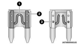
Blade Fuses
- Fuse Element
- Blade Fuse with a good/functional fuse element
- Blade fuse with a bad/not functional fuse element (blown fuse)
Underhood Fuses
The Front Power Distribution Center is located in the engine compartment. This module contains fuses and relays. Fuse cavity location and descriptions are printed on the inside of the power distribution center cover.
CAUTION!
- When installing the power distribution center cover, it is important to ensure the cover is properly positioned and fully latched. Failure to do so may allow water to get into the power distribution center and possibly result in an electrical system failure.
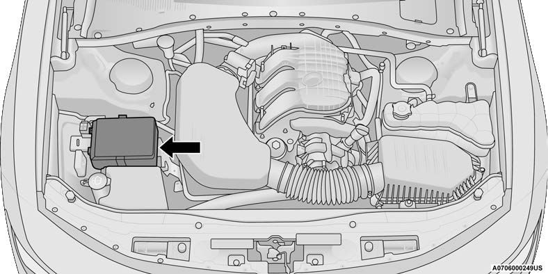
Front Power Distribution Center Location
| Cavity | Cartridge Fuse | Mini-Fuse | Description |
| * If Equipped | |||
| F01 | – | – | Spare |
| F02 | 40 Amp Green | – | Radiator Fan #1 – (Non 6.2L & Non – Police) |
| 50 Amp Red | Radiator Fan (6.2L & Police) | ||
| F03 | 50 Amp Red | – | Electric Power Steering #1 * |
| F04 | 30 Amp Pink | – | Starter |
| F05 | 40 Amp Green | – | Anti-Lock Brake |
| F06 | 30 Amp Pink | – | Anti-Lock Brake |
| F07 | 20 Amp Blue | – | Police Ignition Run / ACC #1 |
| F08 | 20 Amp Blue | – | Police Ignition Run / ACC # 2 |
| F09 | – | 20 Amp Yellow | All-Wheel Drive Module * |
| F10 | – | 10 Amp Red | Intrusion MOD (300) * / Under Hood Lamp – Police |
| F11 | – | 20 Amp Yellow | Horns |
| F12 | – | 10 Amp Red | Air Conditioning Clutch |
| F13 | – | – | Spare |
| F14 | – | – | Spare |
| F15 | – | 20 Amp Yellow | Left HID Headlamp * |
| F16 | – | 20 Amp Yellow | Right HID Headlamp * |
| F18 | 50 Amp Red | – | Radiator Fan #2 |
| F19 | 50 Amp Red | – | Electric Power Steering #2 * |
| F20 | 30 Amp Pink | – | Wiper Motor |
| F21 | 30 Amp Pink | – | Headlamp Washers * |
| 20 Amp Blue – Police | Police Bat Feed #2 | ||
| Cavity | Cartridge Fuse | Mini-Fuse | Description |
| * If Equipped | |||
| F22 | 40 Amp Green | – | LTR Cooling Pump (6.2L Eng) |
| 20 Amp Blue – Police | Police Bat Feed # 3 | ||
| F23 | 20 Amp Blue | – | Police Bat Feed # 1 |
| F24 | 20 Amp Blue | – | Police Ignition Run/ACC Feed # 3 |
| F28 | – | – | Spare |
| F29 | – | 15 Amp Blue | Auto Trans (Challenger / Police) |
| F30 | – | – | Spare |
| F31 | – | 25 Amp Clear | Engine Module |
| F32 | – | – | Spare |
| F33 | – | – | Spare |
| F34 | – | 25 Amp Clear | ASD Feed #1 |
| F35 | – | 20 Amp Yellow | ASD Feed #2 |
| F36 | – | 10 Amp Red | Anti-Lock Brake Module / Steering Column Lock Module * |
| F37 | – | 10 Amp Red | Engine Controller |
| F38 | – | 10 Amp Red | Airbag Module |
| F39 | – | 10 Amp Red | A/C Clutch / EPS */ Vacuum Pump * |
| F48 | – | 10 Amp Red | AWD Module / Front Axle Disconnect * |
| F49 | – | – | Spare |
| F50 | – | – | Spare |
| F51 | – | 20 Amp Yellow | Vacuum Pump * |
| F52 | – | 5 Amp Tan | Adaptive Cruise Control * |
| F53 | – | – | Spare |
Rear Interior Fuses
There is also a power distribution center located in the trunk under the spare tire access panel. This center contains fuses and relays. Fuse cavity location and descriptions are printed on the inside of the power distribution center cover.
CAUTION!
When installing the power distribution center cover, it is important to ensure the cover is properly positioned and fully latched. Failure to do so may allow water to get into the power distribution center and possibly result in an electrical system failure.
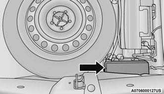
Rear Power Distribution Center
| Cavity | Cartridge Fuse | Mini-Fuse | Description |
| * If Equipped | |||
| F02 | 60 Amp Yellow | – | Front PDC Feed #1 |
| F03 | – | – | Spare |
| F04 | 60 Amp Yellow | – | Front PDC Feed #2 |
| F05 | 30 Amp Pink | – | Sunroof * |
| 20 Amp Blue – Police | Dome Lamp – Police | ||
| F06 | 40 Amp Green | – | Exterior Lighting #1 |
| F07 | 40 Amp Green | – | Exterior Lighting #2 |
| F08 | 30 Amp Pink | – | Interior Lighting |
| F09 | 40 Amp Green | – | Power Locks |
| F10 | 30 Amp Pink | – | Driver Door Control Module |
| F11 | 30 Amp Pink | – | Passenger Door Control Module |
| F12 | – | 20 Amp Yellow | Cigar Lighter / IP APO / RR USB (Selectable Fuse) * |
| Cavity | Cartridge Fuse | Mini-Fuse | Description |
| * If Equipped | |||
| F15 | 40 Amp Green | – | HVAC Blower |
| F16 | 20 Amp Blue | – | Left Spot Lamp – Police |
| F17 | 20 Amp Blue | – | Right Spot Lamp – Police |
| F18 | 30 Amp Pink | – | VISM Mod (Police) |
| F19 | – | – | Spare |
| F20 | – | – | Spare |
| F21 | 30 Amp Pink | – | Fuel Pump (Non 6.2L ADR) |
| 40 Amp Green | Fuel Pump #2 (6.2L XVC) | ||
| F22 | – | 5 Amp Tan | Cyber Gateway Module |
| F23 | – | 10 Amp Red | Fuel Door SW * / Diagnostic Port |
| F24 | – | 10 Amp Red | Integrated Center Stack |
| F25 | – | 10 Amp Red | Tire Pressure Monitor System |
| F26 | – | 15 Amp Blue | Trans Mod (Charger / 300) |
| F27 | – | 25 Amp Clear | Amplifier * |
| F31 | – | 25 Amp Breaker | Power Seats * |
| F32 | – | 15 Amp Blue | HVAC Module / Cluster |
| F33 | – | 15 Amp Blue | IGN SW / Wireless Mod / Steer Clmn Lock Mod / Remote Start * |
| F34 | – | 10 Amp Red | Steering Column Module / Clock (300) |
| F35 | – | 5 Amp Tan | Battery Sensor |
| F36 | – | 15 Amp Blue | Active Exhaust Valve * |
| F37 | – | 20 Amp Yellow | Radio |
| Cavity | Cartridge Fuse | Mini-Fuse | Description |
| * If Equipped | |||
| F38 | – | 20 Amp Yellow | Media Hub / Console APO |
| F40 | 30 Amp Pink | – | Fuel Pump #1 (6.2L ADR) |
| F41 | 30 Amp Pink | – | Fuel Pump #2 (6.2L ADR) |
| 40 Amp Green | Fuel Pump #1 (6.2L XVC) | ||
| F42 | 30 Amp Pink | – | Rear Defrost |
| F43 | – | 20 Amp Yellow | Rear Heated Seats * / Heated Steering Wheel * |
| F44 | – | 10 Amp Red | Park Assist */ Blind Spot */ Rear View Camera * |
| F45 | – | 15 Amp Blue | Cluster / Rearview Mirror / Lane Departure
* |
| F46 | – | – | Spare |
| F47 | – | 10 Amp Red | Adaptive Front Lighting */ Day Time Running Lamps * |
| F48 | – | 20 Amp Yellow | Active Suspension – (6.4L*/ 6.2L) |
| F49 | – | – | Spare |
| F50 | – | – | Spare |
| F51 | – | 20 Amp Yellow | Front Heated */ Vented Seats * |
| F52 | – | 10 Amp Red | Heated Cup Holders */ Rear Heated Seat Switches * |
| F53 | – | 10 Amp Red | HVAC Module / In Vehicle Temperature Sensor |
| F54 | – | – | Spare |
| F55 | – | – | Spare |
| Cavity | Cartridge Fuse | Mini-Fuse | Description |
| * If Equipped | |||
| F56 | – | – | Spare |
| F57 | – | – | Spare |
| F58 | – | 10 Amp Red | Airbag Module |
| F59 | – | 20 Amp Yellow | Adjustable Pedals – Police |
| F60 | – | – | Spare |
| F61 | – | – | Spare |
| F62 | – | – | Spare |
| F63 | – | – | Spare |
| F64 | – | 25 Amp Breaker | Rear Windows (Charger/300) |
| F65 | – | 10 Amp Red | Airbag Module |
| F66 | – | – | Spare |
| F67 | – | 10 Amp Red | Rain & Light Sensor */ Sunroof */ Inside RearView Mirror / Police Run Acc |
| F68 | – | 10 Amp Red | Rear USB Timer / Rear Sunshade * |
| F69 | – | – | Spare |
| F70 | – | – | Spare |
REPLACEMENT
Replacement Bulbs, Names, And Part Numbers
In the instance a bulb needs to be replaced, this section includes bulb description and replacement part numbers.
NOTE:
See an authorized dealer for LED bulb replacement.
| Interior Bulbs | |
| Bulb Name | Bulb Number |
| Rear Courtesy/Reading Lamps | W5W |
| Rear Compartment (Trunk) Lamp | 562 |
| Overhead Console Reading Lamps | 578 |
| Visor Vanity Lamps | A6220 |
| Glove Compartment Lamp – If Equipped | 194 |
| Door Courtesy | 562 |
| Shift Indicator Lamp | JKLE14140 |
| Optional Door Map Pocket/Cupholder | LED |
| For lighted switches, see an authorized dealer for replacement instructions. | |
| Exterior Bulbs | |
| Bulb Name | Bulb Number |
| Headlamp – High Intensity Discharge (HID) | D3S (Serviced at an authorized dealer) * |
| Halogen Headlamp | HIR2LL |
| Front Park/Turn Lamp | LED |
| Front Fog Lamp | H11LL |
| Front Side Marker | LED |
| Tail Lamp | LED |
| Stop/Turn Lamp | LED |
| Rear Side Marker | LED |
| Backup Lamp | LED |
| Center High Mount Stop Lamp (CHMSL) | LED |
| License | LED |
* The headlamps are a type of high-voltage discharge tube. High voltage can remain in the circuit even with the headlamp switch off and the key removed. Because of this, you should not attempt to service a headlamp bulb yourself. If a headlamp bulb fails, take your vehicle to an authorized dealer for service.
Replacing Exterior Bulbs
LOW BEAM HEADLAMP, HIGH BEAM HEADLAMP — MODELS WITH HALOGEN HEADLAMPS — IF EQUIPPED
See below steps to replace:
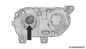
- Open the hood.
 Headlamp Assembly Dust Cap Location
NOTE:
Removal of the air cleaner filter housing may be necessary prior to replacing bulbs in the headlamp assembly on the driver side of the vehicle.
- Remove the large dust cap from the headlamp housing by turning it counterclockwise.
- Turn the bulb counterclockwise, and remove.
 Headlamp Location
 - Disconnect the bulb from the socket assembly and install the replacement bulb.
- Reinstall the bulb and socket assembly into the headlamp assembly, and then turn it clockwise.
CAUTION! Do not touch the new bulb with your fingers. Oil contamination will severely shorten bulb life. If the bulb comes in contact with any oily surface, clean the bulb with rubbing alcohol. - Reinstall the access cap making sure it is seated into the housing and turn cap clockwise to engage locking lugs. Visually, you should be unable to see the blue O-ring gasket. The access cap should be uniformly seated and you should not be able to pull the access cap off without turning it counterclockwise.
CAUTION!
If the access cap is not installed correctly after bulb replacement, the lamp becomes susceptible to dust, condensation, and water intrusion. This may ultimately lead to an inoperative lamp. If the access cap cannot be installed correctly, please return to an authorized dealer for proper repair or access cap replacement if necessary.
LOW BEAM HEADLAMP, HIGH BEAM HEAD-LAMP — MODELS WITH HIGH INTENSITY DISCHARGE (HID) HEADLAMPS — IF EQUIPPED
The headlamps are a type of high voltage discharge tube. High voltage can remain in the circuit even with the headlamp switch off and the key removed. Because of this, you should not attempt to service a headlamp bulb yourself. If a headlamp bulb fails, take your vehicle to an authorized dealer for service.
WARNING!
A transient high voltage occurs at the bulb sockets of HID headlamps when the headlamp switch is turned ON. It may cause serious electrical shock or electrocution if not serviced properly. See an authorized dealer for service.
NOTE:
On vehicles equipped with HID headlamps, when the headlamps are turned on, there is a blue hue to the lamps. This diminishes and becomes more white after approximately 10 seconds, as the system charges.
FRONT PARK/SIGNATURE LAMP
The Front Park/Signature function is part of the headlamp assembly and use LED lamps that are not serviceable separately. The headlamps must be replaced as an assembly, see an authorized dealer.
FRONT TURN/DRL LAMP
The Front Turn/DRL function is part of the headlamp assembly and use LED lamps that are not serviceable separately. The headlamps must be replaced as an assembly, see an authorized dealer.
FRONT/REAR SIDE MARKER LAMP
The Side Markers use LED lamps that are not serviceable separately. The Side Markers must be replaced as an assembly, see an authorized dealer.
TAIL/TURN AND STOP LAMP
The Tail/Turn and Stop Lamps use LED lamps that are not serviceable separately. The Tail/Turn and Stop Lamps must be replaced as an assembly, see an authorized dealer.
CENTER TAIL/BACKUP LAMP
The Center Tail/Backup Lamp use LED lamps that are not serviceable separately. The Center Tail/Backup Lamp must be replaced as an assembly; see an authorized dealer.
CENTER HIGH MOUNTED STOP LAMP (CHMSL)
The CHMSL Lamp uses LED sources that are not serviceable separately. The CHMSL Lamp must be replaced as an assembly; see an authorized dealer.
LICENSE LAMP
The License Lamp uses an LED source that is not serviceable separately. The License Lamp must be replaced as an assembly; see an authorized dealer.
TIRES
TIRE SAFETY INFORMATION
Tire safety information will cover aspects of the following information: Tire Markings, Tire Identification Numbers, Tire Terminology and Definitions, Tire Pressures, and Tire Loading.
Tire Markings
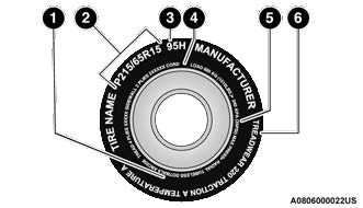
- US DOT Safety Standards Code (TIN)
- Size Designation
- Service Description
- Maximum Load
- Maximum Pressure
- Treadwear, Traction and Temperature Grades
NOTE:
- P (Passenger) — Metric tire sizing is based on US design standards. P-Metric tires have the letter “P” molded into the sidewall preceding the size designation. Example: P215/65R15 95H.
- European — Metric tire sizing is based on European design standards. Tires designed to this standard have the tire size molded into the side-wall beginning with the section width. The letter “P” is absent from this tire size designation. Example: 215/65R15 96H.
- LT (Light Truck) — Metric tire sizing is based on US design standards. The size designation for LT-Metric tires is the same as for P-Metric tires except for the letters “LT” that are molded into the sidewall preceding the size designation. Example: LT235/85R16.
- Temporary spare tires are designed for temporary emergency use only. Temporary high pressure compact spare tires have the letter “T” or “S” molded into the sidewall preceding the size designation. Example: T145/80D18 103M.
- High flotation tire sizing is based on US design standards and it begins with the tire diameter molded into the sidewall.
Example: 31×10.5 R15 LT. -
EXAMPLE: Example Size Designation: P215/65R15XL 95H, 215/65R15 96H, LT235/85R16C, T145/80D18 103M, 31×10.5 R15 LT P = Passenger car tire size based on US design standards, or
“….blank.. “ = Passenger car tire based on European design standards, or
LT = Light truck tire based on US design standards, or T or S = Temporary spare tire or
31 = Overall diameter in inches (in)
215, 235, 145 = Section width in millimeters (mm)
65, 85, 80 = Aspect ratio in percent (%)
Ratio of section height to section width of tire, or
10.5 = Section width in inches (in)R = Construction code
“R” means radial construction, or
“D” means diagonal or bias construction15, 16, 18 = Rim diameter in inches (in) Service Description: 95 = Load Index
A numerical code associated with the maximum load a tire can carryH = Speed Symbol
A symbol indicating the range of speeds at which a tire can carry a load corresponding to its load index under certain operating conditions
The maximum speed corresponding to the speed symbol should only be achieved under specified operating conditions (i.e., tire pressure, vehicle loading, road conditions, and posted speed limits) -
EXAMPLE: Load Identification:Absence of the following load identification symbols on the sidewall of the tire indicates a Standard Load (SL) tire:
XL = Extra load (or reinforced) tire, or
LL = Light load tire or
C, D, E, F, G = Load range associated with the maximum load a tire can carry at a specified pressureMaximum Load – Maximum load indicates the maximum load this tire is designed to carry Maximum Pressure – Maximum pressure indicates the maximum permissible cold tire inflation pressure for this tire - Tire Identification Number (TIN)
The TIN may be found on one or both sides of the tire; however, the date code may only be on one side. Tires with white sidewalls will have the full TIN, including the date code, located on the white sidewall side of the tire. Look for the TIN on the outboard side of black sidewall tires as mounted on the vehicle. If the TIN is not found on the outboard side, then you will find it on the inboard side of the tire.
| EXAMPLE: |
| DOT MA L9 ABCD 0301 |
| DOT = Department of Transportation This symbol certifies that the tire is in compliance with the US Department of Transportation tire safety standards and is approved for highway use |
| MA = Code representing the tire manufacturing location (two digits) |
| L9 = Code representing the tire size (two digits) |
| ABCD = Code used by the tire manufacturer (one to four digits) |
| EXAMPLE: |
| 03 = Number representing the week in which the tire was manufactured (two digits) 03 means the 3rd week |
| 01 = Number representing the year in which the tire was manufactured (two digits) 01 means the year 2001 Prior to July 2000, tire manufacturers were only required to have one number to represent the year in which the tire was manufactured. Example: 031 could represent the 3rd week of 1981 or 1991 |
Tire Terminology And Definitions
| Term | Definition |
| B-pillar | The vehicle B-pillar is the structural member of the body located behind the front door. |
| Cold Tire Inflation Pressure | Cold tire inflation pressure is defined as the tire pressure after the vehicle has not been driven for at least three hours, or driven less than 1 mile (1.6 km) after sitting for a minimum of three hours. Inflation pressure is measured in units of PSI (pounds per square inch) or kPa (kilopascals). |
| Maximum Inflation Pressure | The maximum inflation pressure is the maximum permissible cold tire inflation pressure for this tire. The maximum inflation pressure is molded into the sidewall. |
| Recommended Cold Tire Inflation Pressure | Vehicle manufacturer’s recommended cold tire inflation pressure as shown on the tire placard. |
| Tire Placard | A label permanently attached to the vehicle describing the vehicle’s loading capacity, the original equipment tire sizes and the recommended cold tire inflation pressures. |
Tire Loading And Tire Pressure
NOTE:
The proper cold tire inflation pressure is listed on the driver’s side B-pillar or the rear edge of the driver’s side door.
Check the inflation pressure of each tire, including the spare tire (if equipped), at least monthly and inflate to the recommended pressure for your vehicle.
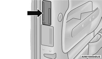
Example Tire Placard Location (Door)
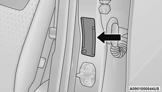
Example Tire Placard Location (B-pillar)
Tire And Loading Information Placard
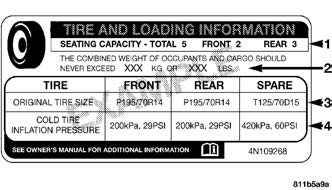
Tire And Loading Information Placard
This placard tells you important information about the:
- Number of people that can be carried in the vehicle.
- Total weight your vehicle can carry.
- Tire size designed for your vehicle.
- Cold tire inflation pressures for the front, rear, and spare tires.
Loading
The vehicle maximum load on the tire must not exceed the load carrying capacity of the tire on your vehicle. You will not exceed the tire’s load carrying capacity if you adhere to the loading conditions, tire size, and cold tire inflation pressures specified on the Tire and Loading Information placard page 97.
NOTE:
Under a maximum loaded vehicle condition, Gross Axle Weight Rating (GAWR) for the front and rear axles must not be exceeded.
For further information on GAWR, vehicle loading, and trailer towing page 97.
To determine the maximum loading conditions of your vehicle, locate the statement “The combined weight of occupants and cargo should never exceed XXX kg or XXX lbs” on the Tire and Loading Information placard. The combined weight of occupants, cargo/luggage and trailer tongue weight (if applicable) should never exceed the weight referenced here.
Steps For Determining Correct Load Limit—
- Locate the statement “The combined weight of occupants and cargo should never exceed XXX kg or XXX lbs.” on your vehicle’s placard.
- Determine the combined weight of the driver and passengers that will be riding in your vehicle.
- Subtract the combined weight of the driver and passengers from XXX kg or XXX lbs.
- The resulting figure equals the available amount of cargo and luggage load capacity. For example, if “XXX” amount equals 1400 lbs. and there will be five 150 lb passengers in your vehicle, the amount of available cargo and luggage load capacity is 650 lbs.(1400-750 (5×150) = 650 lbs.)
- Determine the combined weight of luggage and cargo being loaded on the vehicle. That weight may not safely exceed the available cargo and luggage load capacity calculated in Step 4.
- If your vehicle will be towing a trailer, load from your trailer will be transferred to your vehicle. Consult this manual to determine how this reduces the available cargo and luggage load capacity of your vehicle.
Metric Example For Load Limit
For example, if “XXX” amount equals 635 kg and there will be five 68 kg passengers in your vehicle, the amount of available cargo and luggage load capacity is 295 kg (635-340 (5×68) = 295 kg) as shown in step 4.
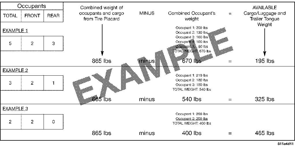
NOTE:
- If your vehicle will be towing a trailer, load from your trailer will be transferred to your vehicle. The following table shows examples on how to calculate total load, cargo/luggage, and towing capacities of your vehicle with varying seating configurations and number and size of occupants. This table is for illustration purposes only and may not be accurate for the seating and load carry capacity of your vehicle.
- For the following example, the combined weight of occupants and cargo should never exceed 865 lbs (392 kg).
WARNING!
Overloading of your tires is dangerous. Overloading can cause tire failure, affect vehicle handling, and increase your stopping distance. Use tires of the recommended load capacity for your vehicle. Never overload them.
TIRES — GENERAL INFORMATION
Tire Pressure
Proper tire inflation pressure is essential to the safe and satisfactory operation of your vehicle. Four primary areas are affected by improper tire pressure:
- Safety
- Fuel Economy
- Tread Wear
- Ride Comfort and Vehicle Stability
Safety
WARNING!
- Improperly inflated tires are dangerous and can cause collisions.
- Underinflation increases tire flexing and can result in overheating and tire failure.
- Overinflation reduces a tire’s ability to cushion shock. Objects on the road and chuckholes can cause damage that result in tire failure.
- Overinflated or underinflated tires can affect vehicle handling and can fail suddenly, resulting in loss of vehicle control.
- Unequal tire pressures can cause steering problems. You could lose control of your vehicle.
- Unequal tire pressures from one side of the vehicle to the other can cause the vehicle to drift to the right or left.
- Always drive with each tire inflated to the recommended cold tire inflation pressure.
Both underinflation and overinflation affect the stability of the vehicle and can produce a feeling of sluggish response or over responsiveness in the steering.
NOTE:
- Unequal tire pressures from side to side may cause erratic and unpredictable steering response.
- Unequal tire pressure from side to side may cause the vehicle to drift left or right.
Fuel Economy
Underinflated tires will increase tire rolling resistance resulting in higher fuel consumption.
Tread Wear
Improper cold tire inflation pressures can cause abnormal wear patterns and reduced tread life, resulting in the need for earlier tire replacement.
Ride Comfort And Vehicle Stability
Proper tire inflation contributes to a comfortable ride. Overinflation produces a jarring and uncomfortable ride.
Tire Inflation Pressures
The proper cold tire inflation pressure is listed on the driver’s side B-pillar or rear edge of the driver’s side door.
At least once a month:
- Check and adjust tire pressure with a good quality pocket-type pressure gauge. Do not make a visual judgment when determining proper inflation. Tires may look properly inflated even when they are underinflated.
- Inspect tires for signs of tire wear or visible damage.
CAUTION!
After inspecting or adjusting the tire pressure, always reinstall the valve stem cap. This will prevent moisture and dirt from entering the valve stem, which could damage the valve stem.
Inflation pressures specified on the placard are always “cold tire inflation pressure”. Cold tire inflation pressure is defined as the tire pressure after the vehicle has not been driven for at least 3 hours, or driven less than 1 mile (1.6 km) after sitting for a minimum of 3 hours. The cold tire inflation pressure must not exceed the maximum inflation pressure molded into the tire sidewall. Check tire pressures more often if subject to a wide range of outdoor temperatures, as tire pressures vary with temperature changes.
Tire pressures change by approximately 1 psi (7 kPa) per 12°F (7°C) of air temperature change. Keep this in mind when checking tire pressure inside a garage, especially in the Winter.
Example: If garage temperature = 68°F (20°C) and the outside temperature = 32°F (0°C) then the cold tire inflation pressure should be increased by 3 psi (21 kPa), which equals 1 psi (7 kPa) for every 12°F (7°C) for this outside temperature condition.
Tire pressure may increase from 2 to 6 psi (13 to 40 kPa) during operation. DO NOT reduce this normal pressure build up or your tire pressure will be too low.
Tire Pressures For High Speed Operation
The manufacturer advocates driving at safe speeds and within posted speed limits. Where speed limits or conditions are such that the vehicle can be driven at high speeds, maintaining correct tire inflation pressure is very important. Increased tire pressure and reduced vehicle loading may be required for high-speed vehicle operation. Refer to an authorized tire dealer or original equipment vehicle dealer for recommended safe operating speeds, loading and cold tire inflation pressures.
WARNING!
High speed driving with your vehicle under maximum load is dangerous. The added strain on your tires could cause them to fail. You could have a serious collision. Do not drive a vehicle loaded to the maximum capacity at continuous speeds above 75 mph (120 km/h).
Radial Ply Tires
WARNING!
Combining radial ply tires with other types of tires on your vehicle will cause your vehicle to handle poorly. The instability could cause a collision. Always use radial ply tires in sets of four. Never combine them with other types of tires.
Tire Repair
If your tire becomes damaged, it may be repaired if it meets the following criteria:
- The tire has not been driven on when flat.
- The damage is only on the tread section of your tire (sidewall damage is not repairable).
- The puncture is no greater than a ¼ of an inch (6 mm).
Consult an authorized tire dealer for tire repairs and additional information.
Damaged Run Flat tires, or Run Flat tires that have experienced a loss of pressure should be replaced immediately with another Run Flat tire of identical size and service description (Load Index and Speed Symbol). Replace the tire pressure sensor as well as it is not designed to be reused.
Run Flat Tires — If Equipped
Run Flat tires allow you the capability to drive 50 miles (80 km) at 50 mph (80 km/h) after a rapid loss of inflation pressure. This rapid loss of inflation is referred to as the Run Flat mode. A Run Flat mode occurs when the tire inflation pressure is of/or below 14 psi (96 kPa). Once a Run Flat tire reaches the Run Flat mode it has limited driving capabilities and needs to be replaced immediately. A Run Flat tire is not repairable. When a Run Flat tire is changed after driving with underinflated tire condition, please replace the TPMS sensor as it is not designed to be reused when driven under Run Flat mode 14 psi (96 kPa) condition.
NOTE:
TPMS sensor must be replaced after driving the vehicle on a flat tire condition.
It is not recommended driving a vehicle loaded at full capacity or to tow a trailer while a tire is in the Run Flat mode.
See the Tire Pressure Monitoring System section for more information.
Tire Spinning
When stuck in mud, sand, snow, or ice conditions, do not spin your vehicle’s wheels above 30 mph (48 km/h) or for longer than 30 seconds continuously without stopping.
For further information page 220 .
WARNING!
Fast spinning tires can be dangerous. Forces generated by excessive wheel speeds may cause tire damage or failure. A tire could explode and injure someone. Do not spin your vehicle’s wheels faster than 30 mph (48 km/h) for more than 30 seconds continuously when you are stuck, and do not let anyone near a spinning wheel, no matter what the speed.
Tread Wear Indicators
Tread wear indicators are in the original equipment tires to help you in determining when your tires should be replaced.
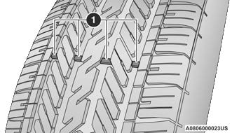
Tire Tread
- Worn Tire
- New Tire
These indicators are molded into the bottom of the tread grooves. They will appear as bands when the tread depth becomes a 1/16 of an inch (1.6 mm). When the tread is worn to the tread wear indicators, the tire should be replaced.
Life Of Tire
The service life of a tire is dependent upon varying factors including, but not limited to:
- Driving style.
- Tire pressure – Improper cold tire inflation pressures can cause uneven wear patterns to develop across the tire tread. These abnormal wear patterns will reduce tread life, resulting in the need for earlier tire replacement.
- Distance driven.
- Performance tires, tires with a speed rating of V or higher, and Summer tires typically have a reduced tread life. Rotation of these tires per the vehicle scheduled maintenance is highly recommended.
WARNING!
Tires and the spare tire should be replaced after six years, regardless of the remaining tread. Failure to follow this warning can result in sudden tire failure. You could lose control and have a collision resulting in serious injury or death.
NOTE:
Wheel valve stem must be replaced as well when installing new tires due to wear and tear in existing tires.
Keep dismounted tires in a cool, dry place with as little exposure to light as possible. Protect tires from contact with oil, grease, and gasoline.
Replacement Tires
The tires on your new vehicle provide a balance of many characteristics. They should be inspected regularly for wear and correct cold tire inflation pressures. The manufacturer strongly recommends that you use tires equivalent to the originals in size, quality and performance when replacement is needed Ú page 299. Refer to the Tire and Loading Information placard or the Vehicle Certification Label for the size designation of your tire. The Load Index and Speed Symbol for your tire will be found on the original equipment tire sidewall.
See the Tire Sizing Chart example found in the “Tire Safety Information” section of this manual for more information relating to the Load Index and Speed Symbol of a tire page 253.
It is recommended to replace the two front tires or two rear tires as a pair. Replacing just one tire can seriously affect your vehicle’s handling. If you ever replace a wheel, make sure that the wheel’s specifications match those of the original wheels.
It is recommended you contact an authorized tire dealer or original equipment dealer with any questions you may have on tire specifications or capability. Failure to use equivalent replacement tires may adversely affect the safety, handling, and ride of your vehicle.
WARNING!
- Do not use a tire, wheel size, load rating, or speed rating other than that specified for your vehicle. Some combinations of unapproved tires and wheels may change suspension dimensions and performance characteristics, resulting in changes to steering, handling, and braking of your vehicle. This can cause unpredictable handling and stress to steering and suspension components. You could lose control and have a collision resulting in serious injury or death. Use only the tire and wheel sizes with load ratings approved for your vehicle.
- Never use a tire with a smaller load index or capacity, other than what was originally equipped on your vehicle. Using a tire with a smaller load index could result in tire over-loading and failure. You could lose control and have a collision.
- Failure to equip your vehicle with tires having adequate speed capability can result in sudden tire failure and loss of vehicle control.
CAUTION!
Replacing original tires with tires of a different size may result in false speedometer and odometer readings.
TIRE TYPES
All Season Tires — If Equipped
All Season tires provide traction for all seasons (Spring, Summer, Autumn, and Winter). Traction levels may vary between different all season tires. All season tires can be identified by the M+S, M&S, M/S or MS designation on the tire sidewall. Use all season tires only in sets of four; failure to do so may adversely affect the safety and handling of your vehicle.
Summer Or Three Season Tires — If Equipped
Summer tires provide traction in both wet and dry conditions, and are not intended to be driven in snow or on ice. If your vehicle is equipped with Summer tires, be aware these tires are not designed for Winter or cold driving conditions. Install Winter tires on your vehicle when ambient temperatures are less than 40°F (5°C) or if roads are covered with ice or snow. For more information, contact an authorized dealer. Summer tires do not contain the all season designation or mountain/snowflake symbol on the tire sidewall. Use Summer tires only in sets of four; failure to do so may adversely affect the safety and handling of your vehicle.
WARNING!
Do not use Summer tires in snow/ice conditions. You could lose vehicle control, resulting in severe injury or death. Driving too fast for conditions also creates the possibility of loss of vehicle control.
Snow Tires
Some areas of the country require the use of snow tires during the Winter. Snow tires can be identified by a “mountain/snowflake” symbol on the tire sidewall.
If you need snow tires, select tires equivalent in size and type to the original equipment tires. Use snow tires only in sets of four; failure to do so may adversely affect the safety and handling of your vehicle.
Snow tires generally have lower speed ratings than what was originally equipped with your vehicle and should not be operated at sustained speeds over 75 mph (120 km/h). For speeds above 75 mph (120 km/h) refer to original equipment or an authorized tire dealer for recommended safe operating speeds, loading and cold tire inflation pressures.
While studded tires improve performance on ice, skid and traction capability on wet or dry surfaces may be poorer than that of non-studded tires. Some states prohibit studded tires; therefore, local laws should be checked before using these tire types.
SPARE TIRES — IF EQUIPPED
NOTE:
For vehicles equipped with Tire Service Kit instead of a spare tire, please refer to “Tire Service Kit” in “In Case Of Emergency” for further information.
CAUTION!
Because of the reduced ground clearance, do not take your vehicle through an automatic car wash with a compact or limited use temporary spare installed. Damage to the vehicle may result.
For restrictions when towing with a spare tire designated for temporary emergency use page 102.
Spare Tire Matching Original Equipped Tire And Wheel — If Equipped
Your vehicle may be equipped with a spare tire and wheel equivalent in look and function to the original equipment tire and wheel found on the front or rear axle of your vehicle. This spare tire may be used in the tire rotation for your vehicle. If your vehicle has this option, refer to an authorized tire dealer for the recommended tire rotation pattern.
Compact Spare Tire — If Equipped
The compact spare is for temporary emergency use only. You can identify if your vehicle is equipped with a compact spare by looking at the spare tire description on the Tire and Loading Information Placard located on the driver’s side door opening or on the sidewall of the tire. Compact spare tire descriptions begin with the letter “T” or “S” preceding the size designation. Example: T145/80D18 103M.
T, S = Temporary Spare Tire
Since this tire has limited tread life, the original equipment tire should be repaired (or replaced) and reinstalled on your vehicle at the first opportunity. Do not install a wheel cover or attempt to mount a conventional tire on the compact spare wheel, since the wheel is designed specifically for the compact spare tire. Do not install more than one compact spare tire and wheel on the vehicle at any given time.
WARNING!
Compact and collapsible spares are for temporary emergency use only. With these spares, do not drive more than 50 mph
(80 km/h). Temporary use spares have limited tread life. When the tread is worn to the tread wear indicators, the temporary use spare tire needs to be replaced. Be sure to follow the warnings, which apply to your spare. Failure to do so could result in spare tire failure and loss of vehicle control.
Collapsible Spare Tire — If Equipped
The collapsible spare is for temporary emergency use only. You can identify if your vehicle is equipped with a collapsible spare by looking at the spare tire description on the Tire and Loading Information Placard located on the driver’s side door opening or on the sidewall of the tire.
Collapsible spare tire description example: 165/80-17 101P.
Since this tire has limited tread life, the original equipment tire should be repaired (or replaced) and reinstalled on your vehicle at the first opportunity.
Inflate collapsible tire only after the wheel is properly installed to the vehicle. Inflate the collapsible tire using the electric air pump before lowering the vehicle.
Do not install a wheel cover or attempt to mount a conventional tire on the collapsible spare wheel, since the wheel is designed specifically for the collapsible spare tire.
WARNING!
Compact and Collapsible spares are for temporary emergency use only. With these spares, do not drive more than 50 mph
(80 km/h). Temporary use spares have limited tread life. When the tread is worn to the tread wear indicators, the temporary use spare tire needs to be replaced. Be sure to follow the warnings, which apply to your spare. Failure to do so could result in spare tire failure and loss of vehicle control.
Full Size Spare — If Equipped
The full size spare is for temporary emergency use only. This tire may look like the originally equipped tire on the front or rear axle of your vehicle, but it is not. This spare tire may have limited tread life. When the tread is worn to the tread wear indicators, the temporary use full size spare tire needs to be replaced. Since it is not the same as your original equipment tire, replace (or repair) the original equipment tire and reinstall on the vehicle at the first opportunity.
Limited Use Spare — If Equipped
The limited use spare tire is for temporary emergency use only. This tire is identified by a label located on the limited use spare wheel. This label contains the driving limitations for this spare. This tire may look like the original equipped tire on the front or rear axle of your vehicle, but it is not. Installation of this limited use spare tire affects vehicle handling. Since it is not the same as your original equipment tire, replace (or repair) the original equipment tire and reinstall on the vehicle at the first opportunity.
WARNING!
Limited use spares are for emergency use only. Installation of this limited use spare tire affects vehicle handling. With this tire, do not drive more than the speed listed on the limited use spare wheel. Keep inflated to the cold tire inflation pressures listed on your Tire and Loading Information Placard located on the driver’s side B-pillar or the rear edge of the driver’s side door. Replace (or repair) the original equipment tire at the first opportunity and reinstall it on your vehicle. Failure to do so could result in loss of vehicle control.
WHEEL AND WHEEL TRIM CARE
All wheels and wheel trim, especially aluminum and chrome plated wheels, should be cleaned regularly using mild (neutral Ph) soap and water to maintain their luster and to prevent corrosion. Wash wheels with the same soap solution recommended for the body of the vehicle and remember to always wash when the surfaces are not hot to the touch.
Your wheels are susceptible to deterioration caused by salt, sodium chloride, magnesium chloride, calcium chloride, etc., and other road chemicals used to melt ice or control dust on dirt roads. Use a soft cloth or sponge and mild soap to wipe away promptly. Do not use harsh chemicals or a stiff brush. They can damage the wheel’s protective coating that helps keep them from corroding and tarnishing.
CAUTION!
Avoid products or automatic car washes that use acidic solutions or strong alkaline additives or harsh brushes. Many aftermarket wheel cleaners and automatic car washes may damage the wheel’s protective finish. Such damage is not covered by the New Vehicle Limited Warranty. Only car wash soap, Mopar® Wheel Cleaner or equivalent is recommended.
When cleaning extremely dirty wheels including excessive brake dust, care must be taken in the selection of tire and wheel cleaning chemicals and equipment to prevent damage to the wheels. Mopar® Wheel Treatment or Mopar® Chrome Cleaner or their equivalent is recommended or select a non-abrasive, non-acidic cleaner for aluminum or chrome wheels.
CAUTION!
Do not use scouring pads, steel wool, a bristle brush, metal polishes or oven cleaner. These products may damage the wheel’s protective finish. Such damage is not covered by the New Vehicle Limited Warranty. Only car wash soap, Mopar® Wheel Cleaner or equivalent is recommended.
NOTE:
If you intend parking or storing your vehicle for an extended period after cleaning the wheels with wheel cleaner, drive your vehicle and apply the brakes to remove the water droplets from the brake components.
This activity will remove the red rust on the brake rotors and prevent vehicle vibration when braking.
Dark Vapor Chrome, Black Satin Chrome, or Low Gloss Clear Coat Wheels
CAUTION!
If your vehicle is equipped with these specialty wheels, DO NOT USE wheel cleaners, abrasives, or polishing compounds. They will permanently damage this finish and such damage is not covered by the New Vehicle Limited Warranty. HAND WASH ONLY USING MILD SOAP AND WATER WITH A SOFT CLOTH. Used on a regular basis; this is all that is required to maintain this finish.
SNOW TRACTION DEVICES
Use of traction devices require sufficient
tire-to-body clearance. Due to limited clearance, the following snow traction devices are recommended. Follow these recommendations to guard against damage.
- Snow traction device must be of proper size for the tire, as recommended by the snow traction device manufacturer.
- No other tire sizes are recommended for use with the snow traction device.
- Please follow the table below for the recommended tire size, axle and snow traction device:
| RWD
Trim Level |
Axle | Tire/Wheel Size | Snow Traction Device (Maximum Projection Beyond Tire Profile Or Equivalent) |
| SXT | 235/55R18 | ||
| 245/45R20 | |||
| Rear | Peerless Chain Super Z6 Low Profile or Equivalent | ||
| GT | 245/45ZR20 | ||
| R/T | 245/45ZR20 | ||
| 275/40ZR20 |
|
| AWD
Trim Level |
Axle | Tire/Wheel Size | Snow Traction Device (Maximum Projection Beyond Tire Profile Or Equivalent) |
| SXT | 235/55R19 | ||
| Rear | 245/45R20 | S Class | |
| GT | 245/45R20 | ||
| 245/45ZR20 |
WARNING!
Using tires of different size and type (M+S, Snow) between front and rear axles can cause unpredictable handling. You could lose control and have a collision.
CAUTION!
To avoid damage to your vehicle or tires, observe the following precautions:
- Because of restricted traction device clearance between tires and other suspension components, it is important that only traction devices in good condition are used. Broken devices can cause serious damage. Stop the vehicle immediately if noise occurs that could indicate device breakage. Remove the damaged parts of the device before further use.
- Install device as tightly as possible and then retighten after driving about ½ mile (0.8 km). Autosock traction devices do not require retightening.
- Do not exceed 30 mph (48 km/h).
- Drive cautiously and avoid severe turns and large bumps, especially with a loaded vehicle.
- Do not drive for a prolonged period on dry pavement.
- Observe the traction device manufacturer’s instructions on the method of installation, operating speed, and conditions for use. Always use the suggested operating speed of the device manufacturer’s if it is less than 30 mph (48 km/h).
CAUTION!
Do not use traction devices on a compact spare tire.
TIRE ROTATION RECOMMENDATIONS
Tires on the front and rear axles of vehicles operate at different loads and perform different steering, driving, and braking functions. For these reasons, they wear at unequal rates.
These effects can be reduced by timely rotation of tires. The benefits of rotation are especially worthwhile with aggressive tread designs such as those on all season type tires. Rotation will increase tread life, help to maintain mud, snow and wet traction levels, and contribute to a smooth, quiet ride.
For the proper maintenance intervals Ú page 223. The reasons for any rapid or unusual wear should be corrected prior to rotation being performed.
The suggested rotation method is the “rearward cross” shown in the following diagram. This rotation pattern does not apply to some directional tires that must not be reversed.

Tire Rotation (Rearward Cross)
DEPARTMENT OF TRANSPORTATION UNIFORM TIRE QUALITY GRADES
The following tire grading categories were established by the National Highway Traffic Safety Administration. The specific grade rating assigned by the tire’s manufacturer in each category is shown on the sidewall of the tires on your vehicle.
All passenger vehicle tires must conform to Federal safety requirements in addition to these grades.
TREADWEAR
The Treadwear grade is a comparative rating, based on the wear rate of the tire when tested under controlled conditions on a specified government test course. For example, a tire graded 150 would wear one and one-half times as well on the government course as a tire graded 100. The relative performance of tires depends upon the actual conditions of their use, however, and may depart significantly from the norm due to variations in driving habits, service practices, and differences in road characteristics and climate.
TRACTION GRADES
The Traction grades, from highest to lowest, are AA, A, B, and C. These grades represent the tire’s ability to stop on wet pavement, as measured under controlled conditions on specified government test surfaces of asphalt and concrete. A tire marked C may have poor traction performance.
WARNING!
The traction grade assigned to this tire is based on straight-ahead braking traction tests, and does not include acceleration, cornering, hydroplaning, or peak traction characteristics.
TEMPERATURE GRADES
The Temperature grades are A (the highest), B, and C, representing the tire’s resistance to the generation of heat and its ability to dissipate heat, when tested under controlled conditions on a specified indoor laboratory test wheel.
Sustained high temperature can cause the material of the tire to degenerate and reduce tire life, and excessive temperature can lead to sudden tire failure. The grade C corresponds to a level of performance, which all passenger vehicle tires must meet under the Federal Motor Vehicle Safety Standard No. 109. Grades B and A represent higher levels of performance on the laboratory test wheel, than the minimum required by law.
WARNING!
The temperature grade for this tire is established for a tire that is properly inflated and not overloaded. Excessive speed, underinflation, or excessive loading, either separately or in combination, can cause heat buildup and possible tire failure.
VEHICLE STORAGE
If you are leaving your vehicle dormant for more than 3 weeks, you may want to take these steps to protect your battery.
- Disconnect the negative cable from the battery.
- Anytime you store your vehicle, or keep it out of service (e.g., vacation) for two weeks or more, run the air conditioning system at idle for about five minutes in the fresh air and high blower setting. This will ensure adequate system lubrication to minimize the possibility of compressor damage when the system is started again.
BODYWORK
PROTECTION FROM ATMOSPHERIC
AGENTS
Vehicle body care requirements vary according to geographic locations and usage. Chemicals that make roads passable in snow and ice and those that are sprayed on trees and road surfaces during other seasons are highly corrosive to the metal in your vehicle. Outside parking, which exposes your vehicle to airborne contaminants, road surfaces on which the vehicle is operated, extreme hot or cold weather and other extreme conditions will have an adverse effect on paint, metal trim, and underbody protection.
The following maintenance recommendations will enable you to obtain maximum benefit from the corrosion resistance built into your vehicle.
What Causes Corrosion?
Corrosion is the result of deterioration or removal of paint and protective coatings from your vehicle.
The most common causes are:
- Road salt, dirt and moisture accumulation.
- Stone and gravel impact.
- Insects, tree sap and tar.
- Salt in the air near seacoast localities.
- Atmospheric fallout/industrial pollutants.
BODY AND UNDERBODY MAINTENANCE
Cleaning Headlights
Your vehicle is equipped with plastic headlights and fog lights that are lighter and less susceptible to stone breakage than glass headlights.
Plastic is not as scratch resistant as glass and therefore different lens cleaning procedures must be followed.
To minimize the possibility of scratching the lenses and reducing light output, avoid wiping with a dry cloth. To remove road dirt, wash with a mild soap solution followed by rinsing.
Do not use abrasive cleaning components, solvents, steel wool or other aggressive material to clean the lenses.
PRESERVING THE BODYWORK
Washing
- Wash your vehicle regularly. Always wash your vehicle in the shade using Mopar® Car Wash, or a mild car wash soap, and rinse the panels completely with water.
- If insects, tar, or other similar deposits have accumulated on your vehicle, use Mopar® Super Kleen Bug and Tar Remover to remove.
- Use a high quality cleaner wax, such as Mopar® Cleaner Wax to remove road film, stains and to protect your paint finish. Use precautions to not scratch the paint.
- Avoid using abrasive compounds and power buffing that may diminish the gloss or thin out the paint finish.
CAUTION!
- Do not use abrasive or strong cleaning materials such as steel wool or scouring powder that will scratch metal and painted surfaces.
- Use of power washers exceeding 1,200 psi (8,274 kPa) can result in damage or removal of paint and decals.
Special Care
- If you drive on salted or dusty roads or if you drive near the ocean, hose off the undercarriage at least once a month.
- It is important that the drain holes in the lower edges of the doors, rocker panels, and trunk be kept clear and open.
- If you detect any stone chips or scratches in the paint, touch them up immediately.
- If your vehicle is damaged due to a collision or similar cause that destroys the paint and protective coating, have your vehicle repaired as soon as possible.
- If you carry special cargo such as chemicals, fertilizers, deicer salt, etc., be sure that such materials are well packaged and sealed.
- If a lot of driving is done on gravel roads, consider mud or stone shields behind each wheel.
- Use Mopar® Touch Up Paint on scratches as soon as possible. An authorized dealer has touch up paint to match the color of your vehicle.
INTERIORS
SEATS AND FABRIC PARTS
Use Mopar® Total Clean to clean fabric upholstery and carpeting.
WARNING!
Do not use volatile solvents for cleaning purposes. Many are potentially flammable, and if used in closed areas they may cause respiratory harm.
Seat Belt Maintenance
Do not bleach, dye, or clean the belts with chemical solvents or abrasive cleaners. This will weaken the fabric.
If the belts need cleaning, use Mopar® Total Clean, a mild soap solution, or lukewarm water. Do not remove the belts from the vehicle to wash them. Dry with a soft cloth.
Sun damage can also weaken the fabric. Replace the belts if they appear frayed or worn or if the buckles do not work properly.
WARNING!
A frayed or torn seat belt could rip apart in a collision and leave you with no protection. Inspect the seat belt system periodically, checking for cuts, frays, or loose parts. Damaged parts must be replaced immediately. Do not disassemble or modify the seat belt system. If your vehicle is involved in a collision, or if you have questions regarding seat belt or retractor conditions, take your vehicle to an authorized FCA dealer or authorized FCA Certified Collision Care Program facility for inspection.
PLASTIC AND COATED PARTS
Use Mopar® Total Clean to clean vinyl upholstery.
CAUTION!
- Direct contact of air fresheners, insect repellents, suntan lotions, or hand sanitizers to the plastic, painted, or decorated surfaces of the interior may cause permanent damage. Wipe away immediately.
- Damage caused by these type of products may not be covered by your New Vehicle Limited Warranty.
Cleaning Plastic Instrument Cluster Lenses
The lenses in front of the instruments in this vehicle are molded in clear plastic. When cleaning the lenses, care must be taken to avoid scratching the plastic.
Clean with a wet soft cloth. A mild soap solution may be used, but do not use high alcohol content or abrasive cleaners. If soap is used, wipe clean with a clean damp cloth. Dry with a soft cloth.
LEATHER SURFACES
Mopar® Total Clean is specifically recommended for leather upholstery.
Your leather upholstery can be best preserved by regular cleaning with a damp soft cloth. Small particles of dirt can act as an abrasive and damage the leather upholstery and should be removed promptly with a damp cloth. Stubborn soils can be removed easily with a soft cloth and Mopar® Total Clean. Care should be taken to avoid soaking your leather upholstery with any liquid. Please do not use polishes, oils, cleaning fluids, solvents, detergents, or ammonia-based cleaners to clean your leather upholstery.
NOTE:
If equipped with light colored leather, it tends to show any foreign material, dirt, and fabric dye transfer more so than darker colors. The leather is designed for easy cleaning, and the manufacturer recommends Mopar® total care leather cleaner applied on a cloth to clean the leather seats as needed.
CAUTION!
Do not use Alcohol and Alcohol-based and/or Ketone based cleaning products to clean leather upholstery, as damage to the upholstery may result.
GLASS SURFACES
All glass surfaces should be cleaned on a regular basis with Mopar® Glass Cleaner, or any commercial household-type glass cleaner. Never use an abrasive type cleaner. Use caution when cleaning the inside rear window equipped with electric defrosters or windows equipped with radio antennas. Do not use scrapers or other sharp instruments that may scratch the elements.
When cleaning the rear view mirror, spray cleaner on the towel or cloth that you are using. Do not spray cleaner directly on the mirror.
Useful Links
View Full Manual: Dodge Challenger 2023 User Manual | Auto User Guide
Download Manual: Owner’s Manuals & User Guides | Dodge