Dodge Durango 2022 Transmission User Manual
STARTING AND OPERATING
STARTING THE ENGINE
Before starting your vehicle, adjust your seat, adjust the inside and outside mirrors, fasten your seat belt, and if present, instruct all other occupants to buckle their seat belts.
WARNING!
- Before exiting a vehicle, always come to a complete stop, then shift the automatic trans-mission into PARK and apply the parking brake.
- Always make sure the keyless ignition node is in the OFF position, key fob is removed from the vehicle and vehicle is locked.
- Never leave children alone in a vehicle, or with access to an unlocked vehicle. Leaving children in a vehicle unattended is dangerous for a number of reasons. A child or others could be seriously or fatally injured. Children should be warned not to touch the parking brake, brake pedal or the gear selector.
WARNING!
- Do not leave the key fob in or near the vehicle, or in a location accessible to children, and do not leave the ignition of a vehicle equipped with Keyless Enter ‘n Go™ in the ACC or ON/RUN position. A child could operate power windows, other controls, or move the vehicle.
Do not leave children or animals inside parked vehicles in hot weather. Interior heat buildup may cause serious injury or death. - AUTOMATIC TRANSMISSION
- The gear selector must be in the PARK position before you can start the engine. Apply the brakes before shifting into any driving gear.
CAUTION!
Damage to the transmission may occur if the following precautions are not observed:
- Do not shift from REVERSE (R), PARK, or NEUTRAL into any forward gear when the engine is above idle speed.
Shift into or out of PARK or REVERSE only after the vehicle has come to a complete stop and the engine is at idle speed.
Before shifting into any gear, make sure your foot is firmly pressing the brake pedal.
To Turn Off The Engine Using The ENGINE START/STOP Button
- Place the gear selector in PARK, then push and release the ENGINE START/STOP button. The ignition will return to the OFF position.
- If the gear selector is not in PARK, the ENGINE START/STOP button must be held for two seconds or three short pushes in a row with the vehicle speed above 5 mph (8 km/h) before the engine will shut off. The ignition will remain in the ACC position until the gear selector is in PARK and the button is pushed twice to the OFF position.
- If the gear selector is not in PARK and the ENGINE START/STOP button is pushed once with the vehicle speed above 5 mph (8 km/h), the instrument cluster will display a “Vehicle Not In Park” message and the engine will remain running. Never leave a vehicle out of the PARK position, or it could roll.
NOTE:
If the gear selector is not in PARK, and the ENGINE START/STOP button is pushed once with the vehicle speed below 5 mph (8 km/h), the engine will shut off and the ignition will remain in the ACC position. If vehicle speed drops below 1.2 mph (1.9 km/h), the vehicle may AutoPark. See AutoPark section for further details.
ENGINE START/STOP Button Functions — With Driver’s Foot OFF The Brake Pedal (In PARK Or NEUTRAL Position)
The ENGINE START/STOP button operates similar to an ignition switch. It has three positions: OFF, ACC, and ON/RUN. To change the ignition positions without starting the vehicle and use the accessories, follow these directions:
- Start with the ignition in the OFF position.
Push the ENGINE START/STOP button once to place the ignition to the ACC position. - Push the ENGINE START/STOP button a second time to place the ignition to the ON/RUN position.
- Push the ENGINE START/STOP button a third time to return the ignition to the OFF position.
NOTE:
Only press one pedal at a time while driving the vehicle. Torque performance of the vehicle could be reduced if both pedals are pressed at the same time. If pressure is detected on both pedals simultaneously, a warning message will display in the instrument cluster page 82.
AUTOPARK
AutoPark is a supplemental feature to assist in placing the vehicle in PARK should the situations on the following pages occur. It is a back up system and should not be relied upon as the primary method by which the driver shifts the vehicle into PARK.
The conditions under which AutoPark will engage are outlined on the following pages.
WARNING!
- Driver inattention could lead to failure to place the vehicle in PARK. ALWAYS DO A VISUAL CHECK that your vehicle is in PARK by verifying that a solid (not blinking) “P” is indicated in the instrument cluster display and on the gear selector. If the “P” indicator is blinking, your vehicle is not in PARK. As an added precaution, always apply the parking brake when exiting the vehicle.
- AutoPark is a supplemental feature. It is not designed to replace the need to shift your vehicle into PARK. It is a back up system and should not be relied upon as the primary method by which the driver shifts the vehicle into PARK.
If the vehicle is not in PARK and the driver turns off the engine, the vehicle may AutoPark.
AutoPark will engage when all of these conditions are met:
- Vehicle is equipped with an 8-speed transmission
- Vehicle is not in PARK
Vehicle speed is 1.2 mph (1.9 km/h) or less
Ignition switched from RUN to ACC
NOTE:
For Keyless Enter ‘n Go™ equipped vehicles, the engine will turn off and the ignition switch will change to ACC position. After 30 minutes, the ignition switches to OFF automatically, unless the driver turns the ignition switch OFF.
If the vehicle is not in PARK and the driver exits the vehicle with the engine running, the vehicle may AutoPark.
AutoPark will engage when all of these conditions are met:
- Vehicle is equipped with an 8-speed transmission
Vehicle is not in PARK
Vehicle speed is 1.2 mph (1.9 km/h) or less
Driver’s seat belt is unbuckled
Driver’s door is ajar
Brake pedal is not pressed
The message “AutoPark Engaged Shift to P then Shift to Gear” will display in the instrument cluster.
NOTE:
In some cases the ParkSense graphic will be displayed in the instrument cluster. In these cases, the gear selector must be returned to “P” to select desired gear.
If the driver shifts into PARK while moving, the vehicle may AutoPark.
AutoPark will engage ONLY when vehicle speed is 1.2 mph (1.9 km/h) or less.
The message “Vehicle Speed is Too High to Shift to P” will be displayed in the instrument cluster if vehicle speed is above 1.2 mph (1.9 km/h).
WARNING!
If vehicle speed is above 1.2 mph (1.9 km/h), the transmission will default to NEUTRAL until the vehicle speed drops below 1.2 mph (1.9 km/h). A vehicle left in the NEUTRAL position can roll. As an added precaution, always apply the parking brake when exiting the vehicle.
4WD LOW — If Equipped
AutoPark will be disabled when operating the vehicle in 4WD LOW.
The message “AutoPark Disabled” will be displayed in the instrument cluster.
Additional customer warnings will be given when both of these conditions are met:
- Vehicle is not in PARK
- Driver’s door is ajar
The message “AutoPark Not Engaged” will be displayed in the instrument cluster. A warning chime will continue until you shift the vehicle into PARK or the driver’s door is closed.
ALWAYS DO A VISUAL CHECK that your vehicle is in PARK by looking for the “P” in the instrument cluster display and on the gear selector. As an added precaution, always apply the parking brake when exiting the vehicle.
EXTENDED PARK STARTING
NOTE:
Extended Park condition occurs when the vehicle has not been started or driven for at least 30 days.
- Install a battery charger or jumper cables to the battery to ensure a full battery charge during the crank cycle.
- Place the ignition in the START position and release it when the engine starts.
- If the engine fails to start within 10 seconds, place the ignition in the OFF position, wait 10 to 15 seconds to allow the starter to cool, then repeat the “Extended Park Starting” procedure.
- If the engine fails to start after eight attempts, allow the starter to cool for at least
10 minutes, then repeat the procedure.
CAUTION!
To prevent damage to the starter, do not crank continuously for more than 10 seconds at a time. Wait 10 to 15 seconds before trying again.
IF ENGINE FAILS TO START
If the engine fails to start after you have followed the “Normal Starting” and the vehicle has not experienced an extended park condition as defined previously, it may be flooded. Push the accelerator pedal all the way to the floor and hold it there. Crank the engine for no more than 10 seconds. This should clear any excess fuel in case the engine is flooded. Leave the ignition key in the ON/RUN position, release the accelerator pedal and repeat the “Normal Starting” procedure.
WARNING!
- Never pour fuel or other flammable liquid into the throttle body air inlet opening in an attempt to start the vehicle. This could result in flash fire causing serious personal injury.
Do not attempt to push or tow your vehicle to get it started. Vehicles equipped with an automatic transmission cannot be started this way. Unburned fuel could enter the catalytic converter and once the engine has started, ignite and damage the converter and vehicle.
If the vehicle has a discharged battery, booster cables may be used to obtain a start from a booster battery or the battery in another vehicle. This type of start can be dangerous if done improperly page 247.
CAUTION!
To prevent damage to the starter, do not continuously crank the engine for more than 10 seconds at a time. Wait 10 to 15 seconds before trying again.
COLD WEATHER OPERATION
(BELOW –22°F OR −30°C)
To ensure reliable starting at these temperatures, use of an externally powered electric engine block heater (available from an authorized dealer) is recommended.
AFTER STARTING
The idle speed is controlled automatically, and it will decrease as the engine warms up.
ENGINE BREAK-IN RECOMMENDATIONS
A long break-in period is not required for the engine and drivetrain (transmission and axle) in your vehicle.
Drive moderately during the first 300 miles
(500 km). After the initial 60 miles (100 km), speeds up to 50 or 55 mph (80 or 90 km/h) are desirable.
Brief full-throttle acceleration within the limits of local traffic laws contributes to a good break-in. Wide-open throttle acceleration in low gear can be detrimental and should be avoided.
The engine oil installed in the engine at the factory is a high-quality energy conserving type lubricant. Oil changes should be consistent with anticipated climate conditions under which vehicle operations will occur. For the recommended viscosity and quality grades see page 309.
CAUTION!
Never use Non-Detergent Oil or Straight Mineral Oil in the engine or damage may result.
NOTE:
A new engine may consume some oil during its first few thousand miles (kilometers) of operation. This should be considered a normal part of the break-in and not interpreted as an indication of difficulty. Please check your oil level with the engine oil indicator often during the break in period. Add oil as required.
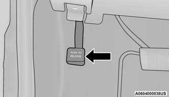
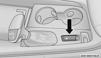
PARKING BRAKE
Before leaving the vehicle, make sure that the parking brake is fully applied and place the gear selector in the PARK (P) position.
The foot operated parking brake is located below the lower left corner of the instrument panel. To apply the parking brake, firmly push the parking brake pedal fully. To release the parking brake, press the parking brake pedal a second time and let your foot up as you feel the brake disengage.
 When the parking brake is applied with the ignition switch in the ON/RUN position, the Brake Warning Light in the instrument cluster will illuminate.
NOTE:
- When the parking brake is applied and the transmission is placed in gear, the Brake Warning Light will flash. If vehicle speed is detected, a chime will sound to alert the driver. Fully release the parking brake before attempting to move the vehicle.
This light only shows that the parking brake is applied. It does not show the degree of brake application.
When parking on a hill, it is important to turn the front wheels toward the curb on a downhill grade and away from the curb on an uphill grade. For vehicles equipped with an automatic transmission, apply the parking brake before placing the gear selector in PARK, otherwise the load on the transmission locking mechanism may make it difficult to move the gear selector out of PARK.
WARNING!
- Never use the PARK position as a substitute for the parking brake. Always apply the parking brake fully when parked to guard against vehicle movement and possible injury or damage.
- When leaving the vehicle, always remove the key fob from the ignition and lock your vehicle.
- Never leave children alone in a vehicle, or with access to an unlocked vehicle. Allowing children to be in a vehicle unattended is dangerous for a number of reasons. A child or others could be seriously or fatally injured. Children should be warned not to touch the parking brake, brake pedal or the gear selector.
- When leaving the vehicle, always make sure the keyless ignition node is in the OFF position, remove the key fob from the vehicle and lock the vehicle.
- Do not leave the key fob in or near the vehicle or in a location accessible to children, and do not leave the ignition of a vehicle equipped with Keyless Enter ‘n Go™ in the ACC or ON/RUN position. A child could operate power windows, other controls, or move the vehicle.
- Be sure the parking brake is fully disengaged before driving; failure to do so can lead to brake failure and a collision.
- Always fully apply the parking brake when leaving your vehicle, or it may roll and cause damage or injury. Also be certain to leave the transmission in PARK. Failure to do so may allow the vehicle to roll and cause damage or injury.
CAUTION!
If the Brake Warning Light remains on with the parking brake released, a brake system malfunction is indicated. Have the brake system serviced by an authorized dealer immediately.
AUTOMATIC TRANSMISSION
You must press and hold the brake pedal while shifting out of PARK.
WARNING!
- Never use the PARK (P) position as a substitute for the parking brake. Always apply the parking brake fully when exiting the vehicle to guard against vehicle movement and possible injury or damage.
- Your vehicle could move and injure you and others if it is not in PARK. Check by trying to move the transmission gear selector out of PARK with the brake pedal released. Make sure the transmission is in PARK before exiting the vehicle.
The transmission may not engage PARK if the vehicle is moving. Always bring the vehicle to a complete stop before shifting to PARK, and verify that the transmission gear position indicator solidly indicates PARK without blinking. Ensure that the vehicle is completely stopped, and the PARK position is properly indicated, before exiting the vehicle. - It is dangerous to shift out of PARK or NEUTRAL (N) if the engine speed is higher than idle speed. If your foot is not firmly pressing the brake pedal, the vehicle could accelerate quickly forward or in reverse. You could lose control of the vehicle and hit someone or something. Only shift into gear when the engine is idling normally and your foot is firmly pressing the brake pedal.
- Unintended movement of a vehicle could injure those in or near the vehicle. As with all vehicles, you should never exit a vehicle while the engine is running. Before exiting a vehicle, always come to a complete stop, then apply the parking brake, shift the transmission into PARK, and turn the ignition OFF. When the ignition is in the OFF position, the transmission is locked in PARK, securing the vehicle against unwanted movement.
When exiting the vehicle, always make sure the ignition is in the OFF position, remove the key fob from the vehicle, and lock the vehicle.
Never leave children alone in a vehicle, or with access to an unlocked vehicle. Allowing children to be in a vehicle unattended is dangerous for a number of reasons. A child or others could be seriously or fatally injured. Children should be warned not to touch the parking brake, brake pedal or the transmission gear selector.
Do not leave the key fob in or near the vehicle (or in a location accessible to children), and do not leave the ignition in the ACC or ON/RUN position. A child could operate power windows, other controls, or move the vehicle.
CAUTION!
Damage to the transmission may occur if the following precautions are not observed:
- Shift into or out of PARK or REVERSE (R) only after the vehicle has come to a complete stop.
- Do not shift between PARK, REVERSE, NEUTRAL, or DRIVE (D) when the engine is above idle speed.
Before shifting into any gear, make sure your foot is firmly pressing the brake pedal.
IGNITION PARK INTERLOCK
This vehicle is equipped with an Ignition Park Interlock which requires the transmission to be in PARK (P) before the ignition can be turned to the OFF position. This helps the driver avoid inadvertently leaving the vehicle without placing the transmission in PARK. This system also locks the transmission in PARK whenever the ignition is in the OFF position.
NOTE:
The transmission is NOT locked in PARK when the ignition is in the ACC position (even though the engine will be off). Ensure that the transmission is in PARK, and the ignition is OFF (not in ACC position) before exiting the vehicle.
BRAKE TRANSMISSION SHIFT
INTERLOCK (BTSI) SYSTEM
This vehicle is equipped with a BTSI system that holds the transmission gear selector in PARK unless the brakes are applied. To shift the transmission out of PARK, the engine must be running and the brake pedal must be pressed. The brake pedal must also be pressed to shift from NEUTRAL into DRIVE or REVERSE when the vehicle is stopped or moving at low speeds.
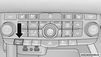
FUEL ECONOMY (ECO) MODE
The Fuel Economy (ECO) mode can improve the vehicle’s overall fuel economy during normal driving conditions. Push the ECO button in the center stack of the instrument panel to activate or disable ECO mode. Or ECO mode can be enabled or disabled through your Uconnect system.
 ECO OFF Button
When the Fuel Economy (ECO) mode is enabled, the vehicle control systems will change the following:
- The transmission will upshift sooner and down-shift later.
The overall driving performance will be more conservative. - Some ECO mode functions may be temporarily inhibited based on temperature and other factors.
8-SPEED AUTOMATIC TRANSMISSION
The transmission gear range is displayed both on the gear selector and in the instrument cluster. To select a gear range, push the lock button on the gear selector and move the selector rearward or forward. To shift the transmission out of PARK, the engine must be running and the brake pedal must be pressed. You must also press the brake pedal to shift from NEUTRAL into DRIVE or REVERSE when the vehicle is stopped or moving at low speeds. Select the DRIVE range for normal driving.
NOTE:
- The transmission electronics are self-calibrating; therefore, the first few shifts on a new vehicle may be somewhat abrupt. This is a normal condition, and precision shifts will develop within a few hundred miles (kilometers).
- In the event of a mismatch between the gear selector position and the actual transmission gear (for example, driver selects PARK while driving), the position indicator will blink continuously until the selector is returned to the proper position, or the requested shift can be completed.
The electronically controlled transmission adapts its shift schedule based on driver inputs, along with environmental and road conditions.
Only shift from DRIVE to PARK or REVERSE when the accelerator pedal is released and the vehicle is stopped. Be sure to keep your foot on the brake pedal when shifting between these gears.
The transmission gear selector provides PARK, REVERSE, NEUTRAL, DRIVE, and MANUAL
(AutoStick) shift positions. Manual shifts can be made using the AutoStick shift control. Toggling the gear selector forward (-) or rearward (+) while in the MANUAL (AutoStick) position (beside the DRIVE position), or tapping the paddle shifters (+/-) (if equipped) will manually select the transmission gear, and will display the current gear in the instrument cluster page 109.
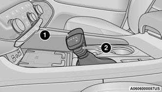 Transmission Gear Selector
- Gear Selector
- Lock Button
NOTE:
If the gear selector cannot be moved to the PARK, REVERSE, or NEUTRAL position (when pushed forward) it is probably in the MANUAL (AutoStick, +/-) position (beside the DRIVE position). In MANUAL (AutoStick) mode, the transmission gear is displayed in the instrument cluster (as 1, 2, 3, etc.). Move the gear selector to the right (into the DRIVE [D] position) for access to PARK, REVERSE, and NEUTRAL.
Gear Ranges
Do not press the accelerator pedal when shifting out of PARK (P) or NEUTRAL (N).
NOTE:
After selecting any gear range, wait a moment to allow the selected gear to engage before acceler-ating. This is especially important when the engine is cold.
PARK (P)
This range supplements the parking brake by locking the transmission. The engine can be started in this range. Never attempt to use PARK while the vehicle is in motion. Apply the parking brake when exiting the vehicle in this range.
When parking on a hill, apply the parking brake before shifting the transmission to PARK. As an added precaution, turn the front wheels toward the curb on a downhill grade and away from the curb on an uphill grade.
NOTE:
On vehicles equipped with the electronically shifted transfer case, ensure that the transfer case is in AWD AUTO or LOW RANGE position on the AWD Control Switch. Ensure that the NEUTRAL position light is NOT illuminated.
When exiting the vehicle, always:
- Apply the parking brake.
- Shift the transmission into PARK.
- Turn the ignition OFF.
- Remove the key fob from the vehicle.
WARNING!
- Never use the PARK (P) position as a substitute for the parking brake. Always apply the parking brake fully when exiting the vehicle to guard against vehicle movement and possible injury or damage.
Your vehicle could move and injure you and others if it is not in PARK. Check by trying to move the transmission gear selector out of PARK with the brake pedal released. Make sure the transmission is in PARK before exiting the vehicle. - The transmission may not engage PARK if the vehicle is moving. Always bring the vehicle to a complete stop before shifting to PARK, and verify that the transmission gear position indicator solidly indicates PARK without blinking. Ensure that the vehicle is completely stopped, and the PARK position is properly indicated, before exiting the vehicle.
- It is dangerous to shift out of PARK or NEUTRAL (N) if the engine speed is higher than idle speed. If your foot is not firmly pressing the brake pedal, the vehicle could accelerate quickly forward or in reverse. You could lose control of the vehicle and hit someone or something. Only shift into gear when the engine is idling normally and your foot is firmly pressing the brake pedal.
- Unintended movement of a vehicle could injure those in or near the vehicle. As with all vehicles, you should never exit a vehicle while the engine is running. Before exiting a vehicle, always come to a complete stop, then apply the parking brake, shift the transmission into PARK, and turn the ignition OFF. When the ignition is in the OFF position, the transmission is locked in PARK, securing the vehicle against unwanted movement.
When exiting the vehicle, always make sure the ignition is in the OFF position, remove the key fob from the vehicle, and lock the vehicle. - Never leave children alone in a vehicle, or with access to an unlocked vehicle. Allowing chil-dren to be in a vehicle unattended is dangerous for a number of reasons. A child or others could be seriously or fatally injured. Children should be warned not to touch the parking brake, brake pedal or the transmission gear selector.
- Do not leave the key fob in or near the vehicle (or in a location accessible to children), and do not leave the ignition in the ACC or ON/RUN position. A child could operate power windows, other controls, or move the vehicle.
CAUTION!
- Before moving the transmission gear selector out of PARK, you must start the engine, and also press the brake pedal. Otherwise, damage to the gear selector could result.
DO NOT race the engine when shifting from PARK or NEUTRAL into another gear range, as this can damage the drivetrain.
The following indicators should be used to ensure that you have properly engaged the transmission into the PARK position:
- When shifting into PARK, push the lock button on the gear selector and firmly move the selector all the way forward until it stops and is fully seated.
Look at the transmission gear position display and verify that it indicates the PARK position (P), and is not blinking.
With brake pedal released, verify that the gear selector will not move out of PARK.
REVERSE (R)
This range is for moving the vehicle backward. Shift into REVERSE only after the vehicle has come to a complete stop.
NEUTRAL (N)
Use this range when the vehicle is standing for prolonged periods with the engine running. Apply the parking brake and shift the transmission into PARK (P) if you must exit the vehicle.
WARNING!
Do not coast in NEUTRAL and never turn off the ignition to coast down a hill. These are unsafe practices that limit your response to changing traffic or road conditions. You might lose control of the vehicle and have a collision.
CAUTION!
Towing the vehicle, coasting, or driving for any other reason with the transmission in NEUTRAL can cause severe transmission damage.
For Recreational Towing page 147.
For Towing A Disabled Vehicle page 253.
DRIVE (D)
This range should be used for most city and highway driving. It provides the smoothest upshifts and downshifts, and the best fuel economy. The transmission automatically upshifts through all forward gears.
When frequent transmission shifting occurs (such as when operating the vehicle under heavy loading conditions, in hilly terrain, traveling into strong head winds, or while towing a heavy trailer), use the AutoStick shift control to select a lower gear page 109. Under these conditions, using a lower gear will improve performance and extend transmission life by reducing excessive shifting and heat buildup.
During cold temperatures, transmission operation may be modified depending on engine and transmission temperature as well as vehicle speed. This feature improves warm up time of the engine and transmission to achieve maximum efficiency. Engagement of the torque converter clutch is inhibited until the transmission fluid is warm. Normal operation will resume once the transmission temperature has risen to a suitable level.
Manual (M)
The MANUAL (M, +/-) position (beside the DRIVE position) enables full manual control of transmission shifting (also known as AutoStick mode page 109). Toggling the gear selector forward (-) or rearward (+) while in the MANUAL (AutoStick) position will manually select the transmission gear, and will display the current gear in the instrument cluster as 1, 2, 3, etc.
Transmission Limp Home Mode
Transmission function is monitored electronically for abnormal conditions. If a condition is detected that could result in transmission damage, Transmission Limp Home Mode is activated. In this mode, the transmission may operate only in certain gears, or may not shift at all. Vehicle performance may be severely degraded and the engine may stall. In some situations, the transmission may not re-engage if the engine is turned off and restarted. The Malfunction Indicator Light (MIL) may be illuminated. A message in the instrument cluster will inform the driver of the more serious conditions, and indicate what actions may be necessary.
In the event of a momentary problem, the transmission can be reset to regain all forward gears by performing the following steps:
NOTE:
In cases where the instrument cluster message indicates the transmission may not re-engage after engine shutdown, perform this procedure only in a desired location (preferably, at an authorized dealer):
- Stop the vehicle.
- Shift the transmission into PARK (P), if possible. If not, shift the transmission to NEUTRAL (N).
- Push and hold the ignition switch until the engine turns off.
- Wait approximately 30 seconds.
- Restart the engine.
- Shift into the desired gear range. If the problem is no longer detected, the transmission will return to normal operation.
NOTE:
Even if the transmission can be reset, we recommend that you visit an authorized dealer at your earliest possible convenience. An authorized dealer has diagnostic equipment to assess the condition of your transmission. If the transmission cannot be reset, authorized dealer service is required.
AutoStick — If Equipped
AutoStick is a driver-interactive transmission feature providing manual shift control, giving you more control of the vehicle. AutoStick allows you to maximize engine braking, eliminate undesirable upshifts and downshifts, and improve overall vehicle performance. This feature can also provide you with more control during passing, city driving, cold slippery conditions, mountain driving, trailer towing, and many other situations.
Operation
In AutoStick mode, you can use the gear selector (in the MANUAL position), or the paddle shifters to the MANUAL (M) position (beside the DRIVE (D) position), or tap one of the paddle shifters on the steering wheel. Tapping the (-) paddle shifter to enter AutoStick mode will downshift the transmission to the next lower gear, while tapping (+) to enter AutoStick mode will retain the current gear. The current transmission gear will be displayed in the instrument cluster.
NOTE:
The paddle shifters (if equipped) may be disabled using the Uconnect Personal Settings.
AutoStick mode has the following operational benefits:
- The transmission will automatically downshift as the vehicle slows (to prevent engine lugging) and will display the current gear.
- The transmission will automatically downshift to FIRST gear when coming to a stop. After a stop, the driver should manually upshift (+) the trans-mission as the vehicle is accelerated.
You can start out, from a stop, in FIRST or SECOND gear. Tapping (+) at a stop will allow starting in SECOND gear. Starting out in SECOND gear can be helpful in snowy or icy conditions. - If a requested downshift would cause the engine to over-speed, that shift will not occur.
- The system will ignore attempts to upshift at too low of a vehicle speed.
- Holding the (-) paddle pressed, or holding the gear selector in the (-) position, will downshift the transmission to the lowest gear possible at the current speed.
Transmission shifting will be more noticeable when AutoStick is enabled.
The system may revert to automatic shift mode if a fault or overheat condition is detected.
To disengage AutoStick mode, return the gear selector to the DRIVE (D) position, or press and hold the (+) paddle shifter until “D” is indicated in the instrument cluster. You can shift in or out of AutoStick mode at any time without taking your foot off the accelerator pedal.
WARNING!
Do not downshift for additional engine braking on a slippery surface. The drive wheels could lose their grip and the vehicle could skid, causing a collision or personal injury.
SPORT MODE — IF EQUIPPED
Your vehicle is equipped with a SPORT Mode feature. The engine, transmission, and steering systems are all set to their SPORT settings. SPORT Mode will provide improved throttle response and modified transmission shift points for an enhanced driving experience, as well as greater amount of steering feel. This mode may be activated and deactivated by pushing the SPORT button on the instrument panel switch bank.
ALL-WHEEL DRIVE OPERATION
SINGLE-SPEED OPERATING INSTRUCTIONS/PRECAUTIONS — IF EQUIPPED
This system contains a single-speed (HI range only) transfer case, which provides convenient full-time All-Wheel Drive (AWD). No driver interaction is required. The Brake Traction Control (BTC) System, which combines standard ABS and Traction Control, provides resistance to any wheel that is slipping to allow additional torque transfer to wheels with traction.
NOTE:
This system is not appropriate for conditions where AWD LOW is recommended page 151.
ELECTRONICALLY SHIFTED TRANSFER CASE — IF EQUIPPED
This is an electronically shifted transfer case and it is operated by the AWD control switch, which is located on the center console.
 AWD Control Switch
This electronically shifted transfer case provides three positions:
- All-wheel drive auto range (AWD AUTO)
- All-wheel drive low range (AWD LOW)
- N (Neutral)
When additional traction is required, the transfer case AWD LOW position can be used to lock the front and rear driveshafts together forcing the front and rear wheels to rotate at the same speed. This is accomplished by pushing the AWD LOW switch page 112. The AWD LOW position is designed for loose, slippery road surfaces only. Driving in the AWD LOW position on dry, hard surfaced roads may cause increased tire wear and damage to the driveline components.
Transfer Case Position Indicator Messages
The Transfer Case Position Indicator message
(AWD LOW) is located in the instrument cluster and indicate the current and desired transfer case selection page 82. When you select a different transfer case position, the position indicator lights will do the following:
If All Shift Conditions Are Met:
- The current position indicator light will turn off.
- The selected position indicator light will flash until the transfer case completes the shift.
- When the shift is complete, the indicator light for the selected position will stop flashing and remain on.
If shift conditions are not met, one or more of the following events may occur:
- The indicator light for the current position will remain on.
- The newly selected position indicator light will continue to flash.
- The transfer case will not shift.
NOTE:
Before retrying a selection, make certain that all the necessary requirements for selecting a new transfer case position have been met page 112.
The “SERV AWD” Warning Light monitors the electronic shift all-wheel drive system. If this light remains on after engine start-up or illuminates during driving, it means that the all-wheel drive system is not functioning properly and that service is required.
WARNING!
Always engage the parking brake when powering down the vehicle if the “SERV AWD” Warning Light is illuminated. Not engaging the parking brake may allow the vehicle to roll which may cause personal injury.
NOTE:
Do not attempt to make a shift while only the front or rear wheels are spinning. This could cause damage to driveline components.
When operating your vehicle in AWD LOW, the engine speed is approximately three times that of the AWD AUTO position at a given road speed. Take care not to overspeed the engine and do not exceed 25 mph (40 km/h).
Proper operation of all-wheel drive vehicles depends on tires of equal size, type and circumference on each wheel. Any difference in tire size can cause damage to the transfer case.
Because all-wheel drive provides improved traction, there is a tendency to exceed safe turning and stopping speeds. Do not go faster than road conditions permit.
For additional information on the appropriate use of each transfer case position, see the information below:
AWD LOW
All-Wheel Drive Low Range – This range provides low speed all-wheel drive. Locks the front and rear driveshafts together forcing the front and rear wheels to rotate at the same speed. Additional traction and maximum pulling power for loose, slippery road surfaces only. Do not exceed 25 mph (40 km/h).
N (Neutral)
This range disengages both the front and rear driveshafts from the powertrain. To be used for flat towing behind another vehicle page 147.
WARNING!
You or others could be injured or killed if you leave the vehicle unattended with the transfer case in the N (Neutral) position without first fully engaging the parking brake. The transfer case N (Neutral) position disengages both the front and rear drive shafts from the powertrain and will allow the vehicle to roll, even if the transmission is in PARK. The parking brake should always be applied when the driver is not in the vehicle.
SHIFTING PROCEDURE
NOTE:
- If any of the requirements to select a new transfer case position have not been met, the transfer case will not shift. The position indicator light for the previous position will remain on and the newly selected position indicator light will continue to flash until all the requirements for the selected position have been met. To retry a shift: return the control switch back to the original position, make certain all shift requirements have been met, wait five seconds and try the shift again.
If all the requirements to select a new transfer case position have been met, the current position indicator light will turn off, the selected position indicator light will flash until the transfer case completes the shift. When the shift is complete, the position indicator light for the selected position will stop flashing and remain on.
AWD AUTO To AWD LOW
NOTE:
When shifting into or out of AWD LOW some gear noise may be heard. This noise is normal and is not detrimental to the vehicle or occupants.
Shifting can be performed with the vehicle rolling 2 to 3 mph (3 to 5 km/h) or completely stopped. Use either of the following procedures:
Preferred Procedure
- With the engine running, slow the vehicle to 2 to 3 mph (3 to 5 km/h).
- Shift the transmission into NEUTRAL.
- While still rolling, push the AWD LOW control switch.
- After the AWD LOW position indicator light is on (not flashing), shift the transmission back into gear.
Alternate Procedure
- 1. Bring the vehicle to complete stop.
2. With the ignition in ON/RUN position and engine running, shift the transmission to NEUTRAL. - 3. Push the AWD LOW control switch.
4. After the AWD LOW position indicator light is on (not flashing), shift the transmission back into gear.
NOTE:
- If steps 1 or 2 of either the “Preferred” or “Alter-nate Procedure” are not satisfied prior to attempting the shift or if they no longer are being met while the shift attempt is in process, the desired position indicator light will flash continuously while the original position indicator light is on, until all requirements have been met.
The ignition switch must be in the ON/RUN position for a shift to take place and for the position indicator lights to be operable. If the ignition switch is not in the ON/RUN position, then the shift will not take place and no position indicator lights will be on or flashing.
N (Neutral) Shift Procedure
For information regarding the transfer case N (Neutral) shift procedure page 149.
TOW N GO — IF EQUIPPED
Tow N Go combines the capabilities of the vehicle control systems, along with driver input, to provide optimum performance for road conditions.
Push any one of the four drive mode buttons to select the desired mode.
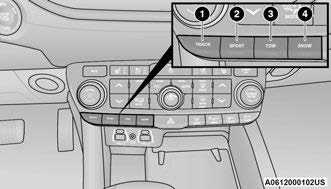 Drive Mode Buttons
- TRACK
- SPORT
- TOW
- SNOW
Tow N Go consists of the following positions:
- TRACK – Optimizes settings for transmission, engine, driveline, and suspension in order to maximize vehicle performance. Also the electric power steering offers more feedback of the tire gripping the road. This feature will reset to AUTO upon an ignition cycle. To turn off Electronic Stability Control (ESC) page 190.
- SPORT – Dry weather, on-road calibration. Performance based tuning that provides a rear-wheel drive feel but with improved handling and acceleration over a two-wheel drive vehicle. This feature will reset to AUTO upon an ignition cycle.
TOW – TOW drive mode also optimizes the transmission shifting for towing, as well as maximizing straight line traction by optimizing drive-line settings on AWD system. Use this mode for towing/hauling. Vehicle suspension will go to SPORT mode. Trailer Sway Control (TSC) is always enabled in all drive modes provided that the ESC OFF indicator light is not illuminated. TSC is disabled when the ESC OFF lamp is illumined. This feature will reset to AUTO upon an ignition cycle.
SNOW – Tuning set for additional stability in inclement weather. Use on and off-road on loose traction surfaces such as snow. This feature will reset to AUTO upon an ignition cycle.
GUIDELINES FOR TRACK USE
NOTE:
The standard Black Brembo Brake Pads are not recommended for track use. Only the Red Brembo Performance calipers are appropriate for track use.
- If your vehicle is equipped with Drive Modes, they will alter the vehicle’s performance in various driving situations. It is recommended that your vehicle operates in SPORT or TRACK modes during the track event.
Prior to each track event, verify all fluids are at the correct levels.
Prior to each track event, verify the front and rear brake pads have more than half pad thick-ness remaining. If the brake pads require changing, complete a brake burnish procedure prior to track outing at full pace.
NOTE:
Use of DOT 4 brake fluid is suggested for extended track usage due to increased thermal capacity.
- At the conclusion of each track event, it is recommended that a brake bleed procedure is performed to maintain the pedal feel and stop-ping capability of your Brembo High Performance brake system.
- It is recommended that each track outing should end with a minimum of one cooldown lap using minimal braking.
It is recommended that the suspension system, brake system, prop shaft, and half shaft boots be checked for wear or damage after every track event. - Track usage results in increased operating temperatures of the engine, transmission, drive-line and brake system. This may affect Noise Vibration Harshness (NVH) countermeasures designed into your vehicle. New components may need to be installed to return the system to the original NVH performance.
- Tire pressure:
- Recommended tire pressure of 33 psi (230 kPa) when tires are cold, or below 42 psi (290 kPa) when hot.
NOTE:
It is recommended that you target below 42 psi (290 kPa) when tires are hot at the conclusion of each track session. Starting at 33 psi (230 kPa) cold and adjusting based on ambient and track conditions is recommended. Tire pressure can be monitored via the instrument cluster display and can assist with adjustments.
Track burnishing your brakes
To avoid “green lining fade” during track use, the brake pads and rotors must have a thermal burnish for factory-installed components or when new brake friction components are installed:
- Use one track session to burnish brakes by driving at 75% speed. Brake at approximately 0.60 – 0.80g max without Anti-Lock Brake System (ABS) intervention.
- Complete one lap in this manner until you start smelling the brakes. Continue for another half lap at speed, then complete a two lap cooldown with minimal brake applications. Ensure the brakes are not smoking. If they are, complete another cooldown lap.
- Getting the brakes to smoke is an indication that the brakes have overheated and may negatively affect future track usage.
- Allow vehicle to sit and cool for at least30 minutes. If an infrared thermal gun is available, allow rotors to cool to 200°F (93.3°C) before returning to the track.
- There should be a thin layer of ash when inspecting the brake pads. Having the ash layer go more than half the thickness of the pad material is a sign of an overly aggressive burnish.
- Occasionally, a second burnish session is required. If the brake pads begin to emit an odor during the next track session, reduce vehicle speed and braking deceleration rate to burnish targets and follow steps 2-4.
- New brake pads installed on old rotors require a burnish. New rotors installed with old brake pads should be burnished at the track or driven for 300 miles (485 km) of city driving to develop an adequate lining transfer layer on the rotor surface prior to track use.
- Rotors that pulsate during track use should be replaced.
NOTE:
Resurfacing of the rotors is not recommended, as it removes mass from the rotor, reducing its thermal capacity. Resurfacing also thins the rotor cheek, making it less robust and increasing the likelihood of pulsation in further track use.
FUEL SAVER TECHNOLOGY 5.7L ONLY — IF EQUIPPED
This feature offers improved fuel economy by shutting off four of the engine’s eight cylinders during light load and cruise conditions. The system is automatic with no driver inputs.
NOTE:
This system may take some time to return to full functionality after a battery disconnect.
POWER STEERING
The electric power steering system will provide increased vehicle response and ease of maneuverability. The power steering system adapts to different driving conditions and adjusts accordingly.
WARNING!
Continued operation with reduced assist could pose a safety risk to yourself and others. Service should be obtained as soon as possible.
Alternate electric power steering efforts can be selected through the Uconnect System page 155.
If the Electric Power Steering warning icon is displayed and the “SERVICE POWER STEERING” or the “POWER STEERING ASSIST OFF – SERVICE SYSTEM” message is displayed within the instrument cluster display, this indicates the vehicle needs to be taken to the dealer for service page 89.
NOTE:
- Even if the power steering assistance is no longer operational, it is still possible to steer the vehicle. Under these conditions there will be a substantial increase in steering effort, espe-cially at low speeds and during parking maneu-vers.
If the condition persists, see an authorized dealer for service.
If the Steering icon is displayed and the “POWER STEERING SYSTEM OVER TEMP” message is displayed on the instrument cluster screen, this indicates an over temperature condition in the power steering system. Once driving conditions are safe, pull over and let the vehicle idle for a few moments until the icon and message turn off.
STOP/START SYSTEM — IF EQUIPPED
The Stop/Start function is developed to reduce fuel consumption. The system will stop the engine automatically during a vehicle stop if the required conditions are met. Releasing the brake pedal or pressing the accelerator pedal will automatically re-start the engine.
This vehicle has been upgraded with a heavy duty starter, enhanced battery, and other upgraded engine parts, to handle the additional engine starts.
AUTOSTOP MODE
The Stop/Start feature is enabled after every normal customer engine start. At that time, the system will go into STOP/START READY.
To Activate The Autostop Mode, The Following Must Occur:
- The system must be in STOP/START READY state. A STOP/START READY message will be displayed in the instrument cluster display within the Stop/Start section Ú page 82.
- The vehicle must be completely stopped.
- The gear selector must be in a forward gear and the brake pedal pressed.
The engine will shut down, the tachometer will move to the zero position and the Stop/Start telltale will illuminate indicating you are in Autostop. Customer settings will be maintained upon return to an engine running condition.
POSSIBLE REASONS THE ENGINE DOES NOT AUTOSTOP
Prior to engine shut down, the system will check many safety and comfort conditions to see if they are fulfilled. Detailed information about the operation of the Stop/Start system may be viewed in the instrument cluster display Stop/Start Screen. In the following situations, the engine will not stop:
- Driver’s seat belt is not buckled.
- Driver’s door is not closed.
- Battery temperature is too warm or cold.
- Battery charge is low.
- The vehicle is on a steep grade.
- Cabin heating or cooling is in process and an acceptable cabin temperature has not been achieved.
- HVAC is set to full defrost mode at a high blower speed.
- HVAC is set to MAX A/C.
- Engine has not reached normal operating temperature.
- The transmission is not in a forward gear.
- Hood is open.
- Brake pedal is not pressed with sufficient pres-sure.
- Accelerator pedal input.
- Engine temp is too high.
- 5 mph (8 km/h) threshold has not been achieved from previous Autostop.
- Steering angle is beyond threshold.
- ACC is on and speed is set.
It may be possible for the vehicle to be driven several times without the Stop/Start system going into a STOP/START READY state under more extreme conditions of the items listed above.
TO START THE ENGINE WHILE IN AUTOSTOP MODE
While in a forward gear, the engine will start when the brake pedal is released or the throttle pedal is pressed. The transmission will automatically
re-engage upon engine restart.
Conditions That Will Cause The Engine To Start Automatically While In Autostop Mode:
- The transmission selector is moved out of DRIVE.
- To maintain cabin temperature comfort.
- HVAC is set to full defrost mode.
- HVAC system temperature or fan speed is manually adjusted.
- Battery voltage drops too low.
- Stop/Start OFF switch is pushed.
- A Stop/Start system error occurs.
- Steering angle is beyond threshold.
TO MANUALLY TURN OFF THE STOP/START SYSTEM
 Stop/Start OFF Switch
Push the Stop/Start OFF switch (located on the switch bank). The light on the switch will illuminate. The “STOP/START OFF” message will appear in the instrument cluster display and the autostop mode will be disabled page 82.
NOTE:
The Stop/Start system will reset itself back to the ON mode every time the ignition is turned OFF and back ON.
TO MANUALLY TURN ON THE STOP/ START SYSTEM
Push the Stop/Start OFF switch (located on the switch bank). The light on the switch will turn off.
SYSTEM MALFUNCTION
If there is a malfunction in the Stop/Start system, the system will not shut down the engine. A “SERVICE STOP/START SYSTEM” message and a yellow Stop/Start telltale will appear in the instrument cluster display page 89.
If the “SERVICE STOP/START SYSTEM” message appears in the instrument cluster display, have the system checked by an authorized dealer.
CRUISE CONTROL SYSTEMS — IF EQUIPPED
Your vehicle may be equipped with the Cruise Control system, or the Adaptive Cruise Control (ACC) system:
- Cruise Control will keep your vehicle at a constant preset speed.
- Adaptive Cruise Control (ACC) will adjust the vehicle speed up to the preset speed to main-tain a distance with the vehicle ahead.
NOTE:
- In vehicles equipped with ACC, if ACC is not enabled, Fixed Speed Cruise Control will not detect vehicles directly ahead of you. Always be aware of the feature selected.
- Only one Cruise Control feature can operate at a time. For example, if Fixed Speed Cruise Control is enabled, Adaptive Cruise Control will be unavailable, and vice versa.
CRUISE CONTROL
When engaged, the Cruise Control takes over accelerator operations at speeds greater than 20 mph (32 km/h).
The Cruise Control buttons are located on the right side of the steering wheel.
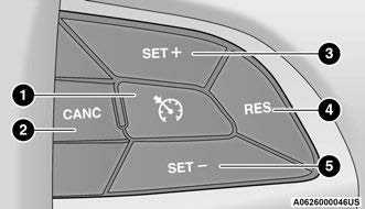 Cruise Control Buttons
- On/Off
- CANC/Cancel
- SET (+)/Accel
- RES/Resume
- SET (-)/Decel
WARNING!
Cruise Control can be dangerous where the system cannot maintain a constant speed. Your vehicle could go too fast for the conditions, and you could lose control and have an accident. Do not use Cruise Control in heavy traffic or on roads that are winding, icy, snow-covered or slippery.
To Activate
Push the on/off button to activate the Cruise Control. “CRUISE CONTROL READY” will appear in the instrument cluster display to indicate the Cruise Control is on. To turn the system off, push the on/off button a second time. “CRUISE CONTROL OFF” will appear in the instrument cluster display to indicate the Cruise Control is off. The system should be turned off when not in use.
WARNING!
Leaving the Cruise Control system on when not in use is dangerous. You could accidentally set the system or cause it to go faster than you want. You could lose control and have an accident. Always leave the system OFF when you are not using it.
To Set A Desired Speed
Turn the Cruise Control on. When the vehicle has reached the desired speed, push the SET (+) or SET (-) button and release. Release the accelerator and the vehicle will operate at the selected speed. Once a speed has been set, a message “CRUISE CONTROL SET TO MPH (km/h)” will appear indicating what speed was set. A cruise indicator lamp, along with set speed will also appear and stay on in the instrument cluster when the speed is set.
To Vary The Speed Setting
To Increase Or Decrease The Set Speed
When the Cruise Control is set, you can increase speed by pushing the SET (+) button, or decrease speed by pushing the SET (-) button.
U.S. Speed (mph)
- Pushing the SET (+), or SET (-) button once will result in a 1 mph speed adjustment. Each subsequent tap of the button results in an adjustment of 1 mph.
- If the button is continually pushed, the set speed will continue to adjust until the button is released, then the new set speed will be established.
Metric Speed (km/h)
- Pushing the SET (+), or SET (-) button once will result in a 1 km/h speed adjustment. Each subsequent tap of the button results in an adjustment of 1 km/h.
If the button is continually pushed, the set speed will continue to adjust until the button is released, then the new set speed will be established.
To Accelerate For Passing
While the Cruise Control is set, press the accelerator to pass as you would normally. When the pedal is released, the vehicle will return to the set speed.
USING CRUISE CONTROL ON HILLS
The transmission may downshift on hills to maintain the vehicle set speed.
The Cruise Control system maintains speed up and down hills. A slight speed change on moderate hills is normal. On steep hills, a greater speed loss or gain may occur so it may be preferable to drive without Cruise Control.
WARNING!
Cruise Control can be dangerous where the system cannot maintain a constant speed. Your vehicle could go too fast for the conditions, and you could lose control and have an accident. Do not use Cruise Control in heavy traffic or on roads that are winding, icy, snow-covered or slippery.
To Resume Speed
To resume a previously set speed, push the RES button and release. Resume can be used at any speed above 20 mph (32 km/h).
To Deactivate
A tap on the brake pedal, pushing the CANC button, or normal brake pressure while slowing the vehicle will deactivate the Cruise Control system without erasing the set speed from memory.
The following conditions will also deactivate the Cruise Control without erasing the set speed from memory:
- Vehicle parking brake is applied
- Stability event occurs
- Gear selector is moved out of DRIVE
Engine overspeed occurs
Pushing the on/off button or placing the ignition in the OFF position will erase the set speed from memory.
ADAPTIVE CRUISE CONTROL (ACC)
Adaptive Cruise Control (ACC) increases the driving convenience provided by Cruise Control while traveling on highways and major roadways. However, it is not a safety system and not designed to prevent collisions. The Cruise Control function performs differently page 117.
ACC will allow you to keep Cruise Control engaged in light to moderate traffic conditions without the constant need to reset your Cruise Control. ACC utilizes a radar sensor and a forward facing camera designed to detect a vehicle directly ahead of you.
NOTE:
- If the ACC sensor detects a vehicle ahead, ACC will apply limited braking or acceleration (not to exceed the original set speed) automatically to maintain a preset following distance, while matching the speed of the vehicle ahead.
- Any chassis/suspension or tire size modifications to the vehicle will affect the performance of the Adaptive Cruise Control and Forward Collision Warning system.
- Fixed Speed Cruise Control (ACC not enabled) will not detect vehicles directly ahead of you. Always be aware of the mode selected page 314.
WARNING!
- Adaptive Cruise Control (ACC) is a conve-nience system. It is not a substitute for active driver involvement. It is always the driver’s responsibility to be attentive of road, traffic, and weather conditions, vehicle speed, distance to the vehicle ahead; and, most importantly, brake operation to ensure safe operation of the vehicle under all road condi-tions. Your complete attention is always required while driving to maintain safe control of your vehicle. Failure to follow these warn-ings can result in a collision and death or serious personal injury.
The ACC system: - Does not react to pedestrians, oncoming vehicles, and stationary objects (e.g., a stopped vehicle in a traffic jam or a disabled vehicle).
- Cannot take street, traffic, and weather conditions into account, and may be limited upon adverse sight distance conditions.
- Does not always fully recognize complex driving conditions, which can result in wrong or missing distance warnings.
- Will bring the vehicle to a complete stop while following a target vehicle and hold the vehicle for two seconds in the stop position. If the target vehicle does not start moving within two seconds the ACC system will display a message that the system will release the brakes and that the brakes must be applied manually. An audible chime will sound when the brakes are released.
You should switch off the ACC system:
- When driving in fog, heavy rain, heavy snow, sleet, heavy traffic, and complex driving situations (i.e., in highway construction zones).
When entering a turn lane or highway off ramp; when driving on roads that are winding, icy, snow-covered, slippery, or have steep uphill or downhill slopes.
When towing a trailer up or down steep slopes.
When circumstances do not allow safe driving at a constant speed.
Adaptive Cruise Control (ACC) Operation
The buttons on the right side of the steering wheel operate the ACC system.
 Adaptive Cruise Control Buttons
- CANC/Cancel
- Fixed Speed Cruise Control On/Off
- Adaptive Cruise Control (ACC) On/Off
- Distance Decrease Button
- SET (+)/Accel
- RES/Resume
- SET (-)/Decel
- Distance Increase Button
Adaptive Cruise Control (ACC) Menu
The instrument cluster display will show the current ACC system settings. The information it displays depends on ACC system status.
Push the Adaptive Cruise Control (ACC) on/off button until one of the following appears in the instrument cluster display:
Adaptive Cruise Control Off
When ACC is deactivated, the display will read
“Adaptive Cruise Control Off.”
Adaptive Cruise Control Ready
When ACC is activated but the vehicle speed setting has not been selected, the display will read “Adaptive Cruise Control Ready.”
Adaptive Cruise Control Set
When the SET (+) or the SET (-) button is pushed, the display will read “ACC SET.”
When ACC is set, the set speed will show in the instrument cluster display.
The ACC screen may display once again if any of the following ACC activity occurs:
- System Cancel
Driver Override
System Off
ACC Proximity Warning
ACC Unavailable Warning
The instrument cluster display will return to the last display selected after five seconds of no ACC display activity.
Activating Adaptive Cruise Control (ACC)
The minimum set speed for the ACC system is 20 mph (32 km/h).
When the system is turned on and in the ready state, the instrument cluster display will read “ACC Ready.”
When the system is off, the instrument cluster display will read “Adaptive Cruise Control (ACC) Off.”
NOTE: You cannot engage ACC under the following conditions:
- When in 4WD Low
When the brakes are applied
When the parking brake is applied
When the automatic transmission is in PARK, REVERSE or NEUTRAL
When the vehicle speed is below the minimum speed range
When the brakes are overheated
When the driver’s door is open at low speeds - When the driver’s seat belt is unbuckled at low speeds
When there is a stationary vehicle in front of your vehicle in close proximity
To Activate/Deactivate
Push and release the Adaptive Cruise Control
(ACC) on/off button. The ACC menu in the instrument cluster displays “ACC Ready.”
To turn the system off, push and release the Adaptive Cruise Control (ACC) on/off button again. At this time, the system will turn off and the instrument cluster displays “Adaptive Cruise Control (ACC) Off.”
WARNING!
Leaving the Adaptive Cruise Control (ACC) system on when not in use is dangerous. You could accidentally set the system or cause it to go faster than you want. You could lose control and have a collision. Always leave the system off when you are not using it.
To Set A Desired Speed
When the vehicle reaches the speed desired, push the SET (+) button or the SET (-) button and release. The instrument cluster display will show the set speed.
NOTE:
Fixed Speed Cruise Control can be used without ACC enabled. To change between the different modes, push the ACC on/off button which turns the ACC and the Fixed Speed Cruise Control off. Pushing the Fixed Speed Cruise Control on/off button will result in turning on (changing to) Fixed Speed Cruise Control mode.
WARNING!
In Fixed Speed Cruise Control mode (ACC not enabled), the system will not react to vehicles ahead. In addition, the proximity warning does not activate and no alarm will sound even if you are too close to the vehicle ahead since neither the presence of the vehicle ahead nor the vehicle-to-vehicle distance is detected. Be sure to maintain a safe distance between your vehicle and the vehicle ahead. Always be aware which mode is selected.
If ACC is set when the vehicle speed is below 20 mph (32 km/h), the set speed will default to 20 mph (32 km/h).
NOTE:
Fixed Speed Cruise Control cannot be set below 20 mph (32 km/h).
If either system is set when the vehicle speed is above 20 mph (32 km/h), the set speed shall be the current speed of the vehicle.
NOTE:
- Keeping your foot on the accelerator pedal can cause the vehicle to continue to accelerate beyond the set speed. If this occurs, the message “DRIVER OVERRIDE” will display in the instrument cluster display.
- If you continue to accelerate beyond the set speed while ACC is enabled, the system will not be controlling the distance between your vehicle and the vehicle ahead. The vehicle speed will only be determined by the position of the accelerator pedal.
To Cancel
The following conditions cancel the ACC or Fixed Speed Cruise Control systems:
- The brake pedal is applied
The CANC (cancel) button is pushed
The Anti-Lock Brake System (ABS) activates
The gear selector is removed from the DRIVE position
The Electronic Stability Control/Traction Control System (ESC/TCS) activates - The vehicle parking brake is applied
The Trailer Sway Control (TSC) activates
The driver switches ESC to Full Off mode
The braking temperature exceeds normal range (overheated)
The following conditions will only cancel the ACC system:
- Driver seat belt is unbuckled at low speeds
Driver door is opened at low speeds
To Turn Off
The system will turn off and erase the set speed in memory if:
- The Adaptive Cruise Control (ACC) on/off button is pushed
The Fixed Speed Cruise Control on/off button is pushed
The ignition is placed in the OFF position
4WD Low is engaged
To Resume
If there is a set speed in memory, push the RES (resume) button and remove your foot from the accelerator pedal. The instrument cluster display will show the last set speed.
Resume can be used at any speed above 20 mph (32 km/h) when only Fixed Speed Cruise Control is being used.
Resume can be used at any speed above 0 mph (0 km/h) when ACC is active.
NOTE:
- While in ACC mode when the vehicle comes to a complete stop longer than two seconds, the system will cancel. The driver will have to apply the brakes to keep the vehicle at a standstill.
ACC cannot be resumed if there is a stationary vehicle in front of your vehicle in close proximity.
WARNING!
The Resume function should only be used if traffic and road conditions permit. Resuming a set speed that is too high or too low for prevailing traffic and road conditions could cause the vehicle to accelerate or decelerate too sharply for safe operation. Failure to follow these warnings can result in a collision and death or serious personal injury.
To Vary The Speed Setting
To Increase Or Decrease The Set Speed
After setting a speed, you can increase the set speed by pushing the SET (+) button, or decrease speed by pushing the SET (-) button.
U.S. Speed (mph)
- Pushing the SET (+), or SET (-) button once will result in a 1 mph speed adjustment. Each subsequent tap of the button results in an adjustment of 1 mph.
If the button is continually pushed, the set speed will continue to adjust in 5 mph increments until the button is released. The new set speed is reflected in the instrument cluster display.
Metric Speed (km/h)
- Pushing the SET (+), or SET (-) button once will result in a 1 km/h speed adjustment. Each subsequent tap of the button results in an adjustment of 1 km/h.
If the button is continually pushed, the set speed will continue to adjust in 10 km/h increments until the button is released. The new set speed is reflected in the instrument cluster display.
NOTE:
When you override and push the SET (+) button or SET (-) button, the new set speed will be the current speed of the vehicle.
When ACC Is Active:
- When you use the SET (-) button to decelerate, if the engine’s braking power does not slow the vehicle sufficiently to reach the set speed, the brake system will automatically slow the vehicle.
The ACC system applies the brake down to a full stop when following the vehicle in front. If your vehicle follows the vehicle in front to a standstill, your vehicle will release the brakes two seconds after coming to a full stop.
The ACC system maintains set speed when driving uphill and downhill. However, a slight speed change on moderate hills is normal. In addition, downshifting may occur while climbing uphill or descending downhill. This is normal operation and necessary to maintain set speed. When driving uphill and downhill, the ACC system will cancel if the braking temperature exceeds normal range (overheated).
Setting The Following Distance In ACC
The specified following distance for ACC can be set by varying the distance setting between four bars (longest), three bars (long), two bars (medium) and one bar (short). Using this distance setting and the vehicle speed, ACC calculates and sets the distance to the vehicle ahead. This distance setting appears in the instrument cluster display.

Distance Settings
- Longest Distance Setting (Four Bars)
- Medium Distance Setting (Two Bars)
- Long Distance Setting (Three Bars)
- Short Distance Setting (One Bar)
To increase the distance setting, push the Distance Increase button and release. Each time the button is pushed, the distance setting increases by one bar (longer).
To decrease the distance setting, push the Distance Decrease button and release. Each time the button is pushed, the distance setting decreases by one bar (shorter).
If there is no vehicle ahead, the vehicle will maintain the set speed. If a slower moving vehicle is detected in the same lane, the instrument cluster display will show the ACC Set With Target Detected Indicator Light. The system will then adjust the vehicle speed automatically to maintain the distance setting, regardless of the set speed.
The vehicle will then maintain the set distance until:
- The vehicle ahead accelerates to a speed above the set speed.
The vehicle ahead moves out of your lane or view of the sensor.
The distance setting is changed. - The system disengages page 120.
The maximum braking applied by ACC is limited; however, the driver can always apply the brakes manually, if necessary.
NOTE:
The brake lights will illuminate whenever the ACC system applies the brakes.
A Proximity Warning will alert the driver if ACC predicts that its maximum braking level is not sufficient to maintain the set distance. If this occurs, a visual alert “BRAKE!” will flash in the instrument cluster display and a chime will sound while ACC continues to apply its maximum braking capacity.
NOTE:
The “BRAKE!” screen in the instrument cluster display is a warning for the driver to take action and does not necessarily mean that the Forward Collision Warning system is applying the brakes autonomously.
Overtake Aid
When driving with Adaptive Cruise Control (ACC) engaged and following a vehicle, the system will provide an additional acceleration up to the ACC set speed to assist in passing the vehicle. This additional acceleration is triggered when the driver utilizes the left turn signal and will only be active when passing on the left hand side.
ACC Operation At Stop
If the ACC system brings your vehicle to a standstill while following a vehicle ahead, your vehicle will resume motion, without any driver interaction, if the vehicle ahead starts moving within two seconds of your vehicle coming to a standstill.
If the target vehicle does not start moving within two seconds of your vehicle coming to a standstill, the ACC with Stop system will cancel and the brakes will release. A cancel message will display on the instrument cluster display and produce a warning chime. Driver intervention will be required at this moment.
While ACC with Stop is holding your vehicle at a standstill, if the driver seat belt is unbuckled or the driver door is opened, the ACC with Stop system will cancel and the brakes will release. A cancel message will display on the instrument cluster display and produce a warning chime. The driver must now manually operate the vehicle’s accelerator and brakes.
WARNING!
When the ACC system is resumed, the driver must ensure that there are no pedestrians, vehicles or objects in the path of the vehicle. Failure to follow these warnings can result in a collision and death or serious personal injury.
Display Warnings And Maintenance
“WIPE FRONT RADAR SENSOR IN FRONT OF VEHICLE” WARNING
The “ACC/FCW Unavailable Wipe Front Radar Sensor” warning will display and a chime will sound when conditions temporarily limit system performance.
This most often occurs at times of poor visibility, such as in snow or heavy rain. The ACC system may also become temporarily blinded due to obstructions, such as mud, dirt or ice. In these cases, the instrument cluster display will display the above message and the system will deactivate.
This message can sometimes be displayed while driving in highly reflective areas (i.e. ice and snow, or tunnels with reflective tiles). The ACC system will recover after the vehicle has left these areas. Under rare conditions, when the radar is not tracking any vehicles or objects in its path this warning may temporarily occur.
NOTE:
If the “ACC/FCW Unavailable Wipe Front Radar Sensor” warning is active, Fixed Speed Cruise Control is still available.
If weather conditions are not a factor, the driver should examine the sensor. It may require cleaning or removal of an obstruction. The sensor is located in the center of the vehicle behind the lower grille.
To keep the ACC system operating properly, it is important to note the following maintenance items:
- Always keep the sensor clean. Carefully wipe the sensor lens with a soft cloth. Be cautious not to damage the sensor lens.
Do not remove any screws from the sensor. Doing so could cause an ACC system malfunction or failure and require a sensor realignment.
If the sensor or front end of the vehicle is damaged due to a collision, see an authorized dealer for service.
Do not attach or install any accessories near the sensor, including transparent material or after-market grilles. Doing so could cause an ACC system failure or malfunction.
When the condition that deactivated the system is no longer present, the system will return to the “Adaptive Cruise Control Off” state and will resume function by simply reactivating it.
NOTE:
- If the “ACC/FCW Unavailable Wipe Front Radar Sensor” message occurs frequently (e.g. more than once on every trip) without any snow, rain, mud, or other obstruction, have the radar sensor realigned at an authorized dealer.
Installing a snowplow, front-end protector, an aftermarket grille or modifying the grille is not recommended. Doing so may block the sensor and inhibit ACC/FCW operation.
“CLEAN FRONT WINDSHIELD” WARNING
The “ACC/FCW Limited Functionality Clean Front Windshield” warning will display, and a chime will sound when conditions temporarily limit system performance. This most often occurs at times of poor visibility, such as in snow or heavy rain and fog. The ACC system may also become temporarily blinded due to obstructions, such as mud, dirt, or ice on windshield and fog on the inside of glass. In these cases, the instrument cluster display will read “ACC/FCW Limited Functionality Clean Front Windshield” and the system will have degraded performance.
This message can sometimes be displayed while driving in adverse weather conditions. The ACC/FCW system will recover after the vehicle has left these areas. Under rare conditions, when the camera is not tracking any vehicles or objects in its path this warning may temporarily occur.
If weather conditions are not a factor, the driver should examine the windshield and the camera located on the back side of the inside rearview mirror. They may require cleaning or removal of an obstruction.
When the condition that created limited functionality is no longer present, the system will return to full functionality.
NOTE:
If the “ACC/FCW Limited Functionality Clean Front Windshield” message occurs frequently (e.g. more than once on every trip) without any snow, rain, mud, or other obstruction, have the windshield and forward facing camera inspected at an authorized dealer.
SERVICE ACC/FCW WARNING
If the system turns off, and the instrument cluster display reads “ACC/FCW Unavailable Service Required” or “Cruise/FCW Unavailable Service Required”, there may be an internal system fault or a temporary malfunction that limits ACC functionality. Although the vehicle is still drivable under normal conditions, ACC will be temporarily unavailable. If this occurs, try activating ACC again later, following an ignition cycle. If the problem persists, see an authorized dealer.
Precautions While Driving With ACC
In certain driving situations, ACC may have detection issues. In these cases, ACC may brake late or unexpectedly. The driver needs to stay alert and may need to intervene. The following are examples of these types of situations:
TOWING A TRAILER
ACC while towing a trailer is recommended only with an Integrated Trailer Brake Controller. Aftermarket trailer brake controllers will not activate the trailer brakes when ACC is braking.
OFFSET DRIVING
ACC may not detect a vehicle in the same lane that is offset from your direct line of travel, or a vehicle merging in from a side lane. There may not be sufficient distance to the vehicle ahead. The offset vehicle may move in and out of the line of travel, which can cause your vehicle to brake or accelerate unexpectedly.
 Offset Driving Condition Example
TURNS AND BENDS
When driving on a curve with ACC engaged, the system may decrease the vehicle speed and acceleration for stability reasons, with no vehicle in front detected. Once the vehicle is out of the curve the system will resume your original set speed. This is a part of normal ACC system functionality.
NOTE:
On tight turns ACC performance may be limited.
USING ACC ON HILLS
ACC performance may be limited when driving on hills. ACC may not detect a vehicle in your lane depending on the speed, vehicle load, traffic conditions, and the steepness of the hill.
 ACC Hill Example
LANE CHANGING
ACC may not detect a vehicle until it is completely in the lane in which you are traveling. In the lane changing example below, ACC has not yet detected the vehicle changing lanes and it may not detect the vehicle until it’s too late for the ACC system to take action. ACC may not detect a vehicle until it is completely in the lane. There may not be sufficient distance to the lane-changing vehicle. Always be attentive and ready to apply the brakes if necessary.
 Lane Changing Example
NARROW VEHICLES
Some narrow vehicles traveling near the outer edges of the lane or edging into the lane are not detected until they have moved fully into the lane. There may not be sufficient distance to the vehicle ahead.
 Narrow Vehicle Example
STATIONARY OBJECTS AND VEHICLES
ACC does not react to stationary objects or vehicles. For example, ACC will not react in situations where the vehicle you are following exits your lane and the vehicle ahead is stopped in your lane. It will consider this stopped vehicle a stationary object as it did not previously detect movement from it. Always be attentive and ready to apply the brakes if necessary.
Stationary Object And Stationary Vehicle Example
PARKSENSE FRONT/REAR PARK ASSIST
SYSTEM — IF EQUIPPED
The ParkSense Park Assist system provides visual and audible indications of the distance between the rear, and if equipped, the front fascia/bumper and a detected obstacle when backing up or moving forward (e.g. during a parking maneuver). The vehicle brakes may be automatically applied and released when performing a reverse parking maneuver if the system detects a possible collision with an obstacle.
NOTE:
- The driver can disable the automatic braking function by turning ParkSense off via the Park-Sense switch. The driver can also override automatic braking by changing the gear or by pressing the gas pedal over 90% of its capacity during the braking event.
- Automatic brakes are not available if the vehicle is in 4WD Low.
- Automatic brakes will not be available if there is a faulted condition detected with the ParkSense Park Assist system or the Braking System Module.
The automatic braking function may only be applied if the vehicle deceleration is not enough to avoid colliding with a detected obstacle. - The automatic braking function may not be applied fast enough for obstacles that move toward the rear of the vehicle from the left and/or right sides.
The automatic braking function can be enabled/disabled from the Customer Programmable Features section of the Uconnect system.
ParkSense will retain its last known configuration state for the automatic braking function through ignition cycles.
The automatic braking function is intended to assist the driver in avoiding possible collisions with detected obstacles when backing up in REVERSE gear.
NOTE:
- The system is designed to assist the driver and not to substitute the driver.
- The driver must stay in full control of the vehicle’s acceleration and braking and is responsible for the vehicle’s movements.
For limitations of this system and recommendations, see page 131.
ParkSense will retain the last system state
(enabled or disabled) from the last ignition cycle when the ignition is changed to the ON/RUN position.
ParkSense can be active only when the gear selector is in REVERSE or DRIVE. If ParkSense is enabled at one of these gear selector positions, the system will remain active until the vehicle speed is increased to approximately 7 mph
(11 km/h) or above. The system will become active again if the vehicle speed is decreased to speeds less than approximately 6 mph (9 km/h). A display warning will appear in the instrument cluster display if the vehicle is in REVERSE and the speed exceeds 7 mph (11 km/h).
PARKSENSE SENSORS
Six ParkSense sensors located in the front fascia/bumper (if equipped) and six ParkSense sensors (four when vehicle is not equipped with front sensors) located in the rear fascia/bumper, monitor the area in front and behind the vehicle that is within the sensors’ field of view. The front sensors detect obstacles from approximately 12 inches (30 cm) up to 47 inches (120 cm) from the front fascia/bumper. The rear sensors can detect obstacles from approximately 12 inches (30 cm) up to 79 inches (200 cm) from the rear fascia/bumper. These distances depend on the location, type and orientation of the obstacle in the horizontal direction.
PARKSENSE DISPLAY
The warning display will turn on indicating the system status when the vehicle is in REVERSE or when the vehicle is in DRIVE and an obstacle has been detected.
The system will indicate a detected obstacle by showing a single arc in the left and/or right front or rear regions based on the object’s distance and location relative to the vehicle.
If an object is detected in the left and/or right rear region, the display will show a single arc in the left and/or right rear region and the system will produce a tone. As the vehicle moves closer to the object, the display will show the single arc moving closer to the vehicle and the tone will change from a single 1/2 second tone to slow, to fast, to continuous.
 Front/Rear ParkSense Arcs
- No Tone/Solid Arc
- No Tone/Flashing Arc
- Fast Tone/Flashing Arc
- Continuous Tone/Flashing Arc
- Continuous Tone/Flashing Arc
- Fast Tone/Flashing Arc
- Fast Tone/Flashing Arc
- Slow Tone/Solid Arc
- Slow Tone/Solid Arc
- Single 1/2 Second Tone/Solid Arc
The vehicle is close to the obstacle when the instrument cluster display shows one flashing arc and sounds a continuous tone. The following chart shows the warning alert operation when the system is detecting an obstacle:
| WARNING ALERTS FOR REAR | |||||||
| Rear Distance (inches/cm) | Greater than 79 inches
(200 cm) |
79-59 inches
(200-150 cm) |
59-47 inches
(150-120 cm) |
47-39 inches
(120-100 cm) |
39-25 inches
(100-65 cm) |
25-12 inches
(65-30 cm) |
Less than 12 inches
(30 cm) |
| Audible Alert Chime | None | Single
1/2 Second Tone |
Slow | Slow | Fast | Fast | Continuous |
| Arcs-Left | None | None | None | None | None | 6th Flashing | 5th Flashing |
| Arcs-Center | None | 10th Solid | 9th Solid | 8th Solid | 7th Flashing | 6th Flashing | 5th Flashing |
| Arcs-Right | None | None | None | None | None | 6th Flashing | 5th Flashing |
| Radio Volume Reduced | No | Yes | Yes | Yes | Yes | Yes | Yes |
| WARNING ALERTS FOR FRONT | |||||
| Front Distance (inches/cm) | Greater than 47 inches (120 cm) | 47-39 inches
(120-100 cm) |
39-25 inches
(100-65 cm) |
25-12 inches
(65-30 cm) |
Less than 12 inches (30 cm) |
| Audible Alert Chime | None | None | None | Fast | Continuous |
| Arcs-Left | None | None | None | 3rd Flashing | 4th Flashing |
| Arcs-Center | None | 1st Solid | 2nd Flashing | 3rd Flashing | 4th Flashing |
| Arcs-Right | None | None | None | 3rd Flashing | 4th Flashing |
| Radio Volume Reduced | No | No | No | Yes | Yes |
NOTE:
If the radio is on, ParkSense will reduce the volume of the radio when the system is sounding an audio tone.
Front Park Assist Audible Alerts
ParkSense will turn off the Front Park Assist audible alert (chime) after approximately three seconds when an obstacle has been detected, the vehicle is stationary, and brake pedal is applied.
Adjustable Chime Volume Settings
- Front and Rear chime volume settings can be selected from the Uconnect system page 155.
The chime volume settings include low, medium, and high.
ParkSense will retain its last known configuration state through ignition cycles.
PARKSENSE WARNING DISPLAY
The ParkSense Warning screen is located within the instrument cluster display page 82. It provides visual warnings to indicate the distance between the rear fascia/bumper and/or front fascia/bumper and the detected obstacle.
The ParkSense Warning screen will only be displayed if Sound and Display is selected from the Customer Programmable Features section of the Uconnect system
page 155.
ENABLING AND DISABLING PARKSENSE
 ParkSense can be enabled and disabled with the ParkSense switch.
When the ParkSense switch is pushed to disable the system, the instrument cluster will display the “PARKSENSE OFF” message for approximately five seconds. When the gear selector is moved to REVERSE and the system is disabled, the instrument cluster display will display the “PARKSENSE OFF” message for as long as the vehicle is in REVERSE.
NOTE:
When ParkSense is disabled and the gear selector is moved to the DRIVE position, no warning message will be displayed.
The ParkSense switch LED will be on when ParkSense is disabled or requires service. The ParkSense switch LED will be off when the system is enabled. If the ParkSense switch is pushed, and the system requires service, the ParkSense switch LED will blink momentarily, and then the LED will be on.
OPERATION WITH A TRAILER
For vehicles equipped with an Integrated Trailer Brake Module (ITBM), the operation of the rear sensors is automatically deactivated when the trailer’s electric plug is inserted in the vehicle’s tow hook socket. The front system is still functional, and the arcs will be overlaid with a “Trailer” message. The rear sensors are automatically reactivated when the trailer’s cable plug is removed.
When the vehicle is connected to a trailer, the instrument cluster display will show the “Rear ParkSense Unavailable Trailer Connected” message in the following situations:
- For five seconds at vehicle start up
For five seconds when the ParkSense button is pushed, as long as an object is not detected in the front
As long as the vehicle is in REVERSE (vehicle graphic displayed with a trailer overlay)
NOTE:
For more information on the Integrated Trailer Brake Module, see page 144.
For vehicles not equipped with ITBM, the automatic braking may falsely be applied if a trailer is hooked up, and park assist is not manually deactivated. It is also possible, the trailer may be mistaken as a close object.
WARNING!
Before using ParkSense, it is strongly recommended that the ball mount and hitch ball assembly be disconnected from the vehicle when the vehicle is not used for towing. Failure to do so can result in injury or damage to vehicles or obstacles because the hitch ball will be much closer to the obstacle than the rear fascia when the vehicle sounds the continuous tone. Also, the sensors could detect the ball mount and hitch ball assembly, depending on its size and shape, giving a false indication that an obstacle is behind the vehicle.
SERVICE THE PARKSENSE PARK ASSIST SYSTEM
During vehicle start up, when the ParkSense System has detected a fault condition, the instrument cluster will actuate a single chime, once per ignition cycle, and it will display the
“PARKSENSE UNAVAILABLE WIPE REAR SENSORS”, “PARKSENSE UNAVAILABLE WIPE FRONT SENSORS”, or the “PARKSENSE UNAVAILABLE SERVICE REQUIRED” message for five seconds.
When the gear selector is moved to REVERSE and the system has detected a fault condition, the instrument cluster display will display a “PARKSENSE UNAVAILABLE WIPE REAR SENSORS”, “PARKSENSE UNAVAILABLE WIPE FRONT SENSORS” or “PARKSENSE UNAVAILABLE SERVICE REQUIRED” pop-up message for five seconds. After five seconds, a vehicle graphic will be displayed with “UNAVAILABLE” at either the front or rear sensor location depending on where the fault is detected. The system will continue to provide arc alerts for the side that is functioning properly. These arc alerts will interrupt the
“PARKSENSE UNAVAILABLE WIPE REAR SENSORS”, “PARKSENSE UNAVAILABLE WIPE FRONT SENSORS”, or “PARKSENSE UNAVAILABLE SERVICE REQUIRED” messages if an object is detected within the five second pop-up duration. The vehicle graphic will remain displayed for as long as the vehicle is in REVERSE.
If “PARKSENSE UNAVAILABLE WIPE REAR SENSORS” or “PARKSENSE UNAVAILABLE WIPE FRONT SENSORS” appears in the instrument cluster display make sure the outer surface and the underside of the rear fascia/bumper and/or front fascia/bumper is clean and clear of snow, ice, mud, dirt or other obstruction and then cycle the ignition. If the message continues to appear see an authorized dealer.
If the “PARKSENSE UNAVAILABLE SERVICE REQUIRED” message appears in the instrument cluster display, see an authorized dealer.
CLEANING THE PARKSENSE SYSTEM
Clean the ParkSense sensors with water, car wash soap and a soft cloth. Do not use rough or hard cloths. Do not scratch or poke the sensors.
PARKSENSE SYSTEM USAGE PRECAUTIONS
NOTE:
- Ensure that the front and rear bumper are free of snow, ice, mud, dirt and debris to keep the ParkSense system operating properly.
Jackhammers, large trucks, and other vibrations could affect the performance of ParkSense.
When you turn ParkSense off, the instrument cluster will display “PARKSENSE OFF.” Further-more, once you turn ParkSense off, it remains off until you turn it on again, even if you cycle the ignition.
When you move the gear selector to the REVERSE position and ParkSense is turned off, the instrument cluster will display “PARKSENSE OFF” for as long as the vehicle is in REVERSE.
ParkSense, when on, will reduce the volume of the radio when it is sounding a tone.
Clean the ParkSense sensors regularly, taking care not to scratch or damage them. The sensors must not be covered with ice, snow, slush, mud, dirt or debris. Failure to do so can result in the system not working properly. The ParkSense system might not detect an obstacle behind or in front of the fascia/bumper, or it could provide a false indication that an obstacle is behind or in front of the fascia/bumper. - Use the ParkSense switch to turn the ParkSense system off if objects such as bicycle carriers, trailer hitches, etc. are placed within 12 inches (30 cm) of the rear fascia/bumper. Failure to do so can result in the system misinterpreting a close object as a sensor problem, causing the “PARKSENSE UNAVAILABLE SERVICE REQUIRED” message to be displayed in the instrument cluster.
ParkSense should be disabled when the liftgate is in the open position. An opened liftgate could provide a false indication that an obstacle is behind the vehicle.
WARNING!
- Drivers must be careful when backing up even when using ParkSense. Always check carefully behind your vehicle, look behind you, and be sure to check for pedestrians, animals, other vehicles, obstructions, and blind spots before backing up. You are responsible for safety and must continue to pay attention to your surroundings. Failure to do so can result in serious injury or death.
- Before using ParkSense, it is strongly recom-mended that the ball mount and hitch ball assembly be disconnected from the vehicle when the vehicle is not used for towing. Failure to do so can result in injury or damage to vehicles or obstacles because the hitch ball will be much closer to the obstacle than the rear fascia when the vehicle sounds the continuous tone. Also, the sensors could detect the ball mount and hitch ball assembly, depending on its size and shape, giving a false indication that an obstacle is behind the vehicle.
CAUTION!
- ParkSense is only a parking aid and it is unable to recognize every obstacle, including small obstacles. Parking curbs might be temporarily detected or not detected at all. Obstacles located above or below the sensors will not be detected when they are in close proximity.
The vehicle must be driven slowly when using ParkSense in order to be able to stop in time when an obstacle is detected. It is recom-mended that the driver looks over his/her shoulder when using ParkSense.
LANESENSE — IF EQUIPPED
LANESENSE OPERATION
The LaneSense system is operational at speeds above 37 mph (60 km/h) and below 112 mph
(180 km/h). The LaneSense system uses a forward looking camera to detect lane markings and measure vehicle position within the lane boundaries.
When both lane markings are detected and the driver drifts out of the lane (no turn signal applied), the LaneSense system provides a haptic warning in the form of torque applied to the steering wheel to prompt the driver to remain within the lane boundaries. If the driver continues to drift out of the lane, the LaneSense system provides a visual warning through the instrument cluster display to prompt the driver to remain within the lane boundaries.
The driver may manually override the haptic warning by applying force into the steering wheel at any time.
When only a single lane marking is detected and the driver drifts across the lane marking (no turn signal applied), the LaneSense system provides visual warnings through the instrument cluster display to prompt the driver to remain within the lane. When only a single lane marking is detected, a haptic or a torque warning will not be provided.
NOTE:
When operating conditions have been met, the LaneSense system will monitor if the driver’s hands are on the steering wheel and provide an audible warning to the driver if removed. The system will cancel if the driver does not return their hands to the wheel.
TURNING LANESENSE ON OR OFF
 The LaneSense button is located on the switch panel below the Uconnect display.
To turn the LaneSense system on, push the LaneSense button (LED turns off). A “LaneSense On” message is shown in the instrument cluster display.
To turn the LaneSense system off, push the LaneSense button once (LED turns on).
NOTE:
The LaneSense system will retain the last system state on or off from the last ignition cycle when the ignition is placed in the ON/RUN position.
LANESENSE WARNING MESSAGE
The LaneSense system will indicate the current lane drift condition through the instrument cluster display.
When the LaneSense system is on, the lane lines are gray when both of the lane boundaries have not been detected and the LaneSense telltale is solid white.
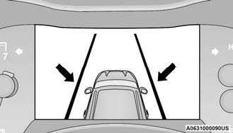 System On (Gray Lines) With White Telltale
Left Lane Departure — Only Left Lane Detected
- When the LaneSense system is on, the Lane-Sense telltale is solid white when only the left lane marking has been detected and the system is ready to provide visual warnings in the instrument cluster display if an unintentional lane departure occurs.
- When the LaneSense system senses the lane has been approached and is in a lane departure situation, the left lane line flashes yellow (on/off), and the LaneSense telltale changes from solid white to flashing yellow.
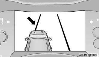 Lane Approached
(Flashing Yellow Line With Flashing Yellow Telltale)- NOTE:
The LaneSense system operates with similar behavior for a right lane departure when only the right lane marking has been detected.
Left Lane Departure — Both Lanes Detected
- When the LaneSense system is on, the lane lines turn from gray to white to indicate that both of the lane markings have been detected. The LaneSense telltale is solid green when both lane markings have been detected and the system is on to provide visual warnings in the instrument cluster display and a torque warning in the steering wheel if an unintentional lane departure occurs.
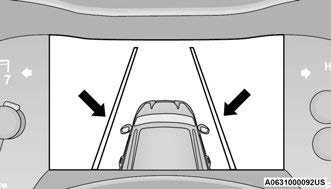 Lanes Sensed (White Lines) With Green Telltale
- When the LaneSense system senses a lane drift situation, the left lane line will turn solid yellow. The LaneSense telltale changes from solid green to solid yellow. At this time torque is applied to the steering wheel in the opposite direction of the lane boundary.
For example: If approaching the left side of the lane the steering wheel will turn to the right.
 Lane Sensed
(Solid Yellow Line With Solid Yellow Telltale)
- When the LaneSense system senses the lane has been approached and is in a lane departure situation, the left lane line flashes yellow (on/off). The LaneSense telltale changes from solid yellow to flashing yellow. At this time torque is applied to the steering wheel in the opposite direction of the lane boundary.
For example: If approaching the left side of the lane the steering wheel will turn to the right.
 Lane Approached
(Flashing Yellow Line With Flashing Yellow Telltale)
- NOTE:
The LaneSense system operates with similar behavior for a right lane departure.
CHANGING LANESENSE STATUS
The LaneSense system has settings to adjust the intensity of the torque warning and the warning zone sensitivity (early/late) that you can configure through the Uconnect system page 155.
NOTE:
- When enabled the system operates above 37 mph (60 km/h) and below 112 mph (180 km/h).
- The warnings are disabled with use of the turn signal.
- The system will not apply torque to the steering wheel whenever a safety system engages (Anti-Lock Brakes, Traction Control System, Electronic Stability Control, Forward Collision Warning, etc.).
PARKVIEW REAR BACK UP CAMERA
- Your vehicle is equipped with the ParkView Rear Back Up Camera that allows you to see an
on-screen image of the rear surroundings of your vehicle whenever the gear selector is put into REVERSE. The image will be displayed on the Navigation/Multimedia radio display screen along with a caution note to “Check Entire Surroundings” across the top of the screen. After five seconds this note will disappear. The ParkView camera is located on the rear of the vehicle above the rear license plate.
When the vehicle is shifted out of REVERSE (with camera delay turned off), the rear camera mode is exited and the previous screen appears.
Manual Activation Of The Backup Camera
- Press the Vehicle Menu button located at the bottom of the Uconnect display. Then select the Controls tab.
- Press the Rear View Camera button to turn the Rear View Camera system on.
NOTE:
The ParkView Rear Back Up Camera has program-mable modes of operation that may be selected through the Uconnect system page 155. In certain radio configurations, these modes of oper-ation will be found in the “Camera” section of the vehicle settings menu.
When the vehicle is shifted out of REVERSE (with camera delay turned off), the rear camera mode is exited and the previous screen appears. When the vehicle is shifted out of REVERSE (with camera delay turned on), the camera image will continue to be displayed for up to 10 seconds after shifting out of REVERSE unless the following conditions occur: the vehicle speed exceeds 8 mph (13 km/h), the vehicle is shifted into PARK, the vehicle’s ignition is placed in the OFF position, or the touchscreen button “X” to disable the display of the Rear View Camera is pressed.
When enabled, active guidelines are overlaid on the image to illustrate the width of the vehicle and its projected backup path based on the steering wheel position. A dashed center line overlay indicates the center of the vehicle to assist with parking or aligning to a hitch/receiver. Different colored zones indicate the distance to the rear of the vehicle.
The following table shows the approximate distances for each zone:
| Zone | Distance To The Rear Of The Vehicle |
| Red | 0 – 1 ft
(0 – 30 cm) |
| Yellow | 1 ft – 6.5 ft
(30 cm – 2 m) |
| Green | 6.5 ft or greater (2 m or greater) |
- WARNING!
Drivers must be careful when backing up even when using the ParkView Rear Back Up Camera. Always check carefully behind your vehicle, and be sure to check for pedestrians, animals, other vehicles, obstructions, or blind spots before backing up. You are responsible for the safety of your surroundings and must continue to pay attention while backing up. Failure to do so can result in serious injury or death.
CAUTION!
- To avoid vehicle damage, ParkView should only be used as a parking aid. The ParkView camera is unable to view every obstacle or object in your drive path.
- To avoid vehicle damage, the vehicle must be driven slowly when using ParkView to be able to stop in time when an obstacle is seen. It is recommended that the driver look frequently over his/her shoulder when using ParkView.
NOTE:
If snow, ice, mud, or any foreign substance builds up on the camera lens, clean the lens, rinse with water, and dry with a soft cloth. Do not cover the lens.
- Rear View Camera — Viewing At Speed

- When the vehicle is in PARK, NEUTRAL or DRIVE, the Rear View Camera can be activated with the Rear View Camera button in the Controls tab of the Vehicle Menu. This feature allows the customer to monitor the area directly behind the vehicle (or trailer, if equipped) for up to 10 seconds while driving. If the vehicle speed remains below 8 mph (13 km/h), the Rear View Camera image will be displayed continuously until deactivated via the “X” button on the touchscreen.
REFUELING THE VEHICLE
- Open the fuel filler door by pushing on the outer edge of the fuel door.
NOTE:
There is no fuel filler cap. Two flapper doors inside the pipe seal the system.
.Insert the fuel nozzle fully into the filler pipe – the nozzle opens and holds the flapper doors while refueling. Fuel Filler
 - Fill the vehicle with fuel – when the fuel nozzle “clicks” or shuts off the fuel tank is full.
- Wait five seconds before removing the fuel nozzle to allow fuel to drain from nozzle.
- Remove the nozzle and push the fuel door all the way in to secure it in place.
WARNING!
- Never have any smoking materials lit in or near the vehicle when the fuel door is open or the tank is being filled.
- Never add fuel when the engine is running. This is in violation of most state and federal fire regulations and may cause the Malfunction Indicator Light to turn on.
WARNING!
- A fire may result if fuel is pumped into a portable container that is inside of a vehicle. You could be burned. Always place fuel containers on the ground while filling.
CAUTION!
- To avoid fuel spillage and overfilling, do not “top off” the fuel tank after filling.
VEHICLE LOADING
CERTIFICATION LABEL
As required by National Highway Traffic Safety Administration regulations, your vehicle has a certification label affixed to the driver’s side door or pillar.
This label contains the month and year of manufacture, Gross Vehicle Weight Rating
(GVWR), front and rear Gross Axle Weight Rating (GAWR), and Vehicle Identification Number (VIN). A Month-Day-Hour (MDH) number is included on this label and indicates the Month, Day and Hour of manufacture. The bar code that appears on the bottom of the label is your VIN.
Gross Vehicle Weight Rating (GVWR)
The GVWR is the total permissible weight of your vehicle including driver, passengers, vehicle, options and cargo. The label also specifies maximum capacities of front and rear (GAWR). Total load must be limited so GVWR and front and rear GAWR are not exceeded.
Payload
The payload of a vehicle is defined as the allowable load weight a truck can carry, including the weight of the driver, all passengers, options and cargo.
Gross Axle Weight Rating (GAWR)
The GAWR is the maximum permissible load on the front and rear axles. The load must be distributed in the cargo area so that the GAWR of each axle is not exceeded.
Each axle GAWR is determined by the components in the system with the lowest load carrying capacity (axle, springs, tires or wheels). Heavier axles or suspension components sometimes specified by purchasers for increased durability does not necessarily increase the vehicle’s GVWR.
Tire Size
The tire size on the Vehicle Certification Label represents the actual tire size on your vehicle. Replacement tires must be equal to the load capacity of this tire size.
Rim Size
This is the rim size that is appropriate for the tire size listed.
Inflation Pressure
This is the cold tire inflation pressure for your vehicle for all loading conditions up to full GAWR.
Curb Weight
The curb weight of a vehicle is defined as the total weight of the vehicle with all fluids, including vehicle fuel, at full capacity conditions, and with no occupants or cargo loaded into the vehicle. The front and rear curb weight values are determined by weighing your vehicle on a commercial scale before any occupants or cargo are added.
Loading
The actual total weight and the weight of the front and rear of your vehicle at the ground can best be determined by weighing it when it is loaded and ready for operation.
The entire vehicle should first be weighed on a commercial scale to ensure that the GVWR has not been exceeded. The weight on the front and rear of the vehicle should then be determined separately to be sure that the load is properly distributed over the front and rear axle. Weighing the vehicle may show that the GAWR of either the front or rear axles has been exceeded but the total load is within the specified GVWR and maximum Payload. If so, weight must be shifted from front to rear or rear to front as appropriate until the specified weight limitations are met. Store the heavier items down low and be sure that the weight is distributed equally. Stow all loose items securely before driving.
Improper weight distributions can have an adverse effect on the way your vehicle steers and handles and the way the brakes operate.
CAUTION!
Do not load your vehicle any heavier than the GVWR, maximum Payload or the maximum front and rear GAWR. If you do, parts on your vehicle can break, or it can change the way your vehicle handles. This could cause you to lose control. Overloading can shorten the life of your vehicle.
TRAILER TOWING
In this section you will find safety tips and information on limits to the type of towing you can reasonably do with your vehicle. Before towing a trailer, carefully review this information to tow your load as efficiently and safely as possible.
To maintain the New Vehicle Limited Warranty coverage, follow the requirements and recommendations in this manual concerning vehicles used for trailer towing.
COMMON TOWING DEFINITIONS
The following trailer towing related definitions will assist you in understanding the following information:
Gross Vehicle Weight Rating (GVWR)
The GVWR is the total allowable weight of your vehicle. This includes driver, passengers, cargo and tongue weight. The total load must be limited so that you do not exceed the GVWR page 137.
Gross Trailer Weight (GTW)
The GTW is the weight of the trailer plus the weight of all cargo, consumables and equipment
(permanent or temporary) loaded in or on the trailer in its “loaded and ready for operation” condition.
The recommended way to measure GTW is to put your fully loaded trailer on a vehicle scale. The entire weight of the trailer must be supported by the scale.
WARNING!
If the gross trailer weight is 5,000 lb (2,267 kg) or more, it is recommended to use a weight-distributing hitch to ensure stable handling of your vehicle. If you use a standard weight-carrying hitch, you could lose control of your vehicle and cause a collision.
Gross Combination Weight Rating (GCWR)
The GCWR is the total allowable weight of your vehicle and trailer when weighed in combination.
Gross Axle Weight Rating (GAWR)
The GAWR is the maximum capacity of the front and rear axles. Distribute the load over the front and rear axles evenly. Make sure that you do not exceed either front or rear GAWR page 137.
WARNING!
It is important that you do not exceed the maximum front or rear GAWR. A dangerous driving condition can result if either rating is exceeded. You could lose control of the vehicle and have a collision.
Tongue Weight (TW)
The TW is the downward force exerted on the hitch ball by the trailer. You must consider this as part of the load on your vehicle.
Trailer Frontal Area
The frontal area is the maximum height multiplied by the maximum width of the front of a trailer.
Trailer Sway Control (TSC)
The TSC can be a mechanical telescoping link that can be installed between the hitch receiver and the trailer tongue that typically provides adjustable friction associated with the telescoping motion to dampen any unwanted trailer swaying motions while traveling.
If equipped, the electronic TSC recognizes a swaying trailer and automatically applies individual wheel brakes and/or reduces engine power to attempt to eliminate the trailer sway.
Weight-Carrying Hitch
A weight-carrying hitch supports the trailer tongue weight, just as if it were luggage located at a hitch ball or some other connecting point of the vehicle. These kinds of hitches are commonly used to tow small and medium sized trailers.
Weight-Distributing Hitch
A weight-distributing system works by applying leverage through spring (load) bars. They are typically used for heavier loads to distribute trailer tongue weight to the tow vehicle’s front axle and the trailer axle(s). When used in accordance with the manufacturer’s directions, it provides for a more level ride, offering more consistent steering and brake control thereby enhancing towing safety. The addition of a friction/hydraulic sway control also dampens sway caused by traffic and crosswinds and contributes positively to tow vehicle and trailer stability. Trailer Sway Control (TSC) and a weight distributing (load equalizing) hitch are recommended for heavier Tongue Weights (TW) and may be required depending on vehicle and trailer configuration/loading to comply with Gross Axle Weight Rating (GAWR) requirements.
WARNING!
- An improperly adjusted weight-distributing hitch system may reduce handling, stability, braking performance, and could result in a collision.
Weight-distributing hitch systems may not be compatible with surge brake couplers. Consult with your hitch and trailer manufacturer or a reputable Recreational Vehicle dealer for additional information.
RECOMMENDED DISTRIBUTION HITCH ADJUSTMENT
- Measure the height from the top of the front wheel opening on the fender to the ground; this is height H1.
 Measuring Height (H)
 - Attach the trailer to the vehicle without the weight distribution bars connected.
- Measure the height from the top of the front wheel opening on the fender to the ground; this is height H2.
- Install and adjust the tension in the weight distributing bars per the manufacturers’ recommendations so that the height of the front fender is approximately (H2-H1)/2+H1 (about 1/2 the difference between H2 and H1 above normal ride height [H1]).
- The vehicle can now be driven.
Measurement Example Example Height (mm) H1 925 H2 946 H2-H1 21 (H2-H1)/2 10.5 (H2-H1)/2 + H1 935.5
NOTE:
For all towing conditions, we recommend towing with tow haul mode engaged (if equipped).
TRAILER HITCH CLASSIFICATION
The following chart provides the industry standard for the maximum trailer weight a given trailer hitch class can tow and should be used to assist you in selecting the correct trailer hitch for your intended towing condition.
| Trailer Hitch Classification Definitions | |
| Class | Max. Trailer Hitch Industry Standards |
| Class I – Light Duty | 2,000 lb (907 kg) |
| Class II – Medium Duty | 3,500 lb (1,588 kg) |
| Class III – Heavy Duty | 6,000 lb (2,721 kg) |
| Class IV – Extra Heavy Duty | 10,000 lb (4,535 kg) |
| For the Maximum Gross Trailer Weight (GTW) towable for your given drivetrain see page 141. | |
| All trailer hitches should be professionally installed on your vehicle. | |
TRAILER TOWING WEIGHTS (MAXIMUM TRAILER WEIGHT RATINGS)
| Engine | GCWR | Maximum GTW | Maximum Trailer TW (See Note) |
| 3.6L – RWD Light Duty Cooling | 8,900 lb (4,037 kg) | 3,500 lb (1,588 kg) | 350 lb (159 kg) |
| 3.6L – RWD | 11,600 lb (5,262 kg) | 6,200 lb (2,812 kg) | 620 lb (281 kg) |
| 3.6L – AWD Light Duty Cooling | 8,900 lb (4,037 kg) | 3,500 lb (1,588 kg) | 350 lb (159 kg) |
| 3.6L – AWD | 11,600 lb (5,262 kg) | 6,200 lb (2,812 kg) | 620 lb (281 kg) |
| 5.7L – RWD | 13,100 lb (5,942 kg) | 7,400 lb (3,357 kg) | 740 lb (336 kg) |
| 5.7L – AWD | 13,100 lb (5,942 kg) | 7,200 lb (3,266 kg) | 720 lb (327 kg) |
| 5.7L – AWD R/T Tow N Go | 14,600 lb (6,622 kg) | 8,700 lb (3,946 kg) | 870 lb (395 kg) |
| Refer to local laws for maximum trailer towing speeds. | |||
NOTE:
The trailer tongue weight must be considered as part of the combined weight of occupants and cargo, and should never exceed the weight refer-enced on the Tire and Loading Information placard page 285. The addition of passengers and cargo may require reducing trailer tongue load and Gross Trailer Weight (GTW).
TRAILER HITCH RECEIVER COVER REMOVAL — IF EQUIPPED
Your vehicle may be equipped with a trailer hitch receiver cover, this must be removed to access the trailer hitch receiver (if equipped). This cover is located at the bottom center of the rear fascia/bumper.
- Turn the two locking retainers located at the bottom of the hitch receiver cover a quarter turn counterclockwise and pull bottom of the hitch receiver cover outward (towards you).
 Hitch Receiver Cover
- Hitch Receiver Cover
- Locking Retainers
- Pull the bottom of the cover outward (towards you) then downwards to disengage the tabs located at the top of the hitch receiver cover to remove.
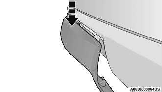 Hitch Receiver Cover
To reinstall the cover after towing, repeat the procedure in reverse order.
NOTE:
Be sure to engage all tabs of the hitch receiver cover in the bumper fascia prior to installation.
TRAILER AND TONGUE WEIGHT
Never exceed the maximum tongue weight stamped on your bumper or trailer hitch.
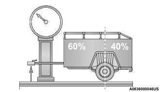 Weight Distribution
CAUTION!
Always load a trailer with 60% of the weight in the front of the trailer. This places 10% of the GTW on the tow hitch of your vehicle. Loads balanced over the wheels or heavier in the rear can cause the trailer to sway severely side to side which will cause loss of control of the vehicle and trailer. Failure to load trailers heavier in front is the cause of many trailer collisions.
Consider the following items when computing the weight on the rear axle of the vehicle:
- The tongue weight of the trailer.
The weight of any other type of cargo or equipment put in or on your vehicle.
The weight of the driver and all passengers.
NOTE:
Remember that everything put into or on the trailer adds to the load on your vehicle. Also, additional factory-installed options or dealer-installed options must be considered as part of the total load on your vehicle. Refer to the Tire And Loading Infor-mation placard for the maximum combined weight of occupants and cargo for your vehicle page 289.
TOWING REQUIREMENTS
To promote proper break-in of the new vehicle drivetrain components, the following guidelines are recommended.
CAUTION!
- Do not tow a trailer at all during the first 500 miles (805 km) the new vehicle is driven. The engine, axle or other parts could be damaged.
- Then, during the first 500 miles (805 km) that a trailer is towed, do not drive over 50 mph (80 km/h) and do not make starts at full throttle. This helps the engine and other parts of the vehicle wear in at the heavier loads.
Perform the maintenance listed in Scheduled Servicing page 256. When towing a trailer, never exceed the GAWR or GCWR ratings.
WARNING!
- Make certain that the load is secured in the trailer and will not shift during travel. When trailering cargo that is not fully secured, dynamic load shifts can occur that may be difficult for the driver to control. You could lose control of your vehicle and have a collision.
When hauling cargo or towing a trailer, do not overload your vehicle or trailer. Overloading can cause a loss of control, poor performance or damage to brakes, axle, engine, transmission, steering, suspension, chassis structure or tires.
Safety chains must always be used between your vehicle and trailer. Always connect the chains to the hook retainers of the vehicle hitch. Cross the chains under the trailer tongue and allow enough slack for turning corners.
Vehicles with trailers should not be parked on a grade. When parking, apply the parking brake on the tow vehicle. Put the tow vehicle transmission in PARK (P). For four-wheel drive vehicles, make sure the transfer case is not in NEUTRAL (N). Always, block or “chock” the trailer wheels.
GCWR must not be exceeded.
Total weight must be distributed between the tow vehicle and the trailer such that the following four ratings are not exceeded:
GVWR
GTW
GAWR
Tongue weight rating for the trailer hitch
Towing Requirements — Tires
- Do not attempt to tow a trailer while using a compact spare tire.
Do not drive more than 50 mph (80 km/h) when towing while using a full size spare tire.
Proper tire inflation pressures are essential to the safe and satisfactory operation of your vehicle. - Check the trailer tires for proper tire inflation pressures before trailer usage.
Check for signs of tire wear or visible tire damage before towing a trailer. - Replacing tires with a higher load carrying capacity will not increase the vehicle’s GVWR and GAWR limits.
For further information page 285.
Towing Requirements — Trailer Brakes
- Do not interconnect the hydraulic brake system or vacuum system of your vehicle with that of the trailer. This could cause inadequate braking and possible personal injury.
An electronically actuated trailer brake controller is required when towing a trailer with electronically actuated brakes. When towing a trailer equipped with a hydraulic surge actuated brake system, an electronic brake controller is not required. - Trailer brakes are recommended for trailers over 1,000 lb (453 kg) and required for trailers in excess of 2,000 lb (907 kg).
WARNING!
- Do not connect trailer brakes to your vehicle’s hydraulic brake lines. It can overload your brake system and cause it to fail. You might not have brakes when you need them and could have an accident.
Towing any trailer will increase your stopping distance. When towing, you should allow for additional space between your vehicle and the vehicle in front of you. Failure to do so could result in an accident.
CAUTION!
If the trailer weighs more than 1,000 lb (453 kg) loaded, it should have its own brakes and they should be of adequate capacity. Failure to do this could lead to accelerated brake lining wear, higher brake pedal effort, and longer stopping distances.
Integrated Trailer Brake Module (ITBM) — If Equipped
Your vehicle may have an ITBM for electric and Electric Over Hydraulic (EOH) trailer brakes.
NOTE:
This module has been designed and verified with electric trailer brakes and EOH systems. Some previous EOH systems may not be compatible with ITBM.
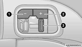 Integrated Trailer Brake Module (ITBM)
- GAIN Adjustment Button
- GAIN Adjustment Button
- Manual Brake Control Lever
The user interface consists of the following:
Manual Brake Control Lever
Slide the manual brake control lever to the left to activate power to the trailer’s electric brakes independent of the tow vehicle’s brakes. If the manual brake control lever is activated while the brake is also applied, the greater of the two inputs determines the power sent to the trailer brakes.
The trailer and the vehicle’s brake lamps will come on when either vehicle braking or manual trailer brakes are applied.
Trailer Brake Status Indicator Light
This light indicates the trailer electrical connection status.
If no electrical connection is detected after the ignition is turned on, pushing the GAIN adjustment button or sliding the manual brake control lever will display the GAIN setting for 10 seconds and the Trailer Brake Status Indicator Light will not be displayed.
If a fault is detected in the trailer wiring or the Integrated Trailer Brake Module (ITBM), the Trailer Brake Status Indicator Light will flash.
GAIN Adjustment Buttons (+/-)
Pushing these buttons will adjust the brake control power output to the trailer brakes in 0.5 increments. The GAIN setting can be increased to a maximum of 10 or decreased to a minimum of 0 (no trailer braking).
GAIN
The GAIN setting is used to set the trailer brake control for the specific towing condition and should be changed as towing conditions change. Changes to towing conditions include trailer load, vehicle load, road conditions and weather.
Adjusting GAIN
NOTE:
This should only be performed in a traffic free environment at speeds of approximately 20–25 mph (30–40 km/h).
- Make sure the trailer brakes are in good working condition, functioning normally and properly adjusted. See a trailer dealer if necessary.
- Hook up the trailer and make the electrical connections according to the trailer manufacturer’s instructions.
- When a trailer with electric/EOH brakes is plugged in, the trailer connected message should appear in the instrument cluster display (if the connection is not recognized by the ITBM, braking functions will not available), the GAIN setting will illuminate and the correct type of trailer must be selected from the instrument cluster display options.
- Push the UP or DOWN button on the steering wheel until “TRAILER TOW” appears on the screen.
Push the RIGHT arrow on the steering wheel to enter “TRAILER TOW”. - Push the UP or DOWN buttons until the Trailer Brake Type appears on the screen.
- Push the RIGHT arrow and then push the UP or DOWN buttons until the proper Trailer Brake Type appears on the screen.
- In a traffic-free environment, tow the trailer on a dry, level surface at a speed of 20–25 mph (30–40 km/h) and squeeze the manual brake control lever completely.
- If the trailer wheels lockup (indicated by squealing tires), reduce the GAIN setting; if the trailer wheels turn freely, increase the GAIN setting.
Repeat steps 8 and 9 until the GAIN setting is at a point just below trailer wheel lockup. If towing a heavier trailer, trailer wheel lockup may not be attainable even with the maximum GAIN setting of 10.
Display Messages
The trailer brake control interacts with the instrument cluster display. Display messages, along with a single chime, will be displayed when a malfunction is determined in the trailer connection, trailer brake control, or on the trailer page 82.
WARNING!
Connecting a trailer that is not compatible with the ITBM system may result in reduced or complete loss of trailer braking. There may be an increase in stopping distance or trailer instability which could result in personal injury.
CAUTION!
Connecting a trailer that is not compatible with the ITBM system may result in reduced or complete loss of trailer braking. There may be an increase in stopping distance or trailer instability which could result in damage to your vehicle, trailer, or other property.
NOTE:
- An aftermarket controller may be available for use with trailers with air or EOH trailer brake systems. To determine the type of brakes on your trailer and the availability of controllers, check with your trailer manufacturer or dealer.
Removal of the ITBM will cause errors and it may cause damage to the electrical system and electronic modules of the vehicle. See an autho-rized dealer if an aftermarket module is to be installed.
Towing Requirements — Trailer Lights And
Wiring
Whenever pulling a trailer, regardless of the trailer size, stoplights and turn signals on the trailer are required for motoring safety.
The Trailer Tow Package may include a four- and seven-pin wiring harness. Use a factory approved trailer harness and connector.
NOTE:
Do not cut or splice wiring into the vehicle’s wiring harness.
The electrical connections are all complete to the vehicle but you must mate the harness to a trailer connector. Refer to the following illustrations.
NOTE:
- Disconnect trailer wiring connector from the vehicle before launching a boat (or any other device plugged into vehicle’s electrical connect) into water.
Be sure to reconnect once clear from water area.
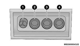 Four-Pin Connector
- Ground
- Park
- Left Stop/Turn
- Right Stop/Turn
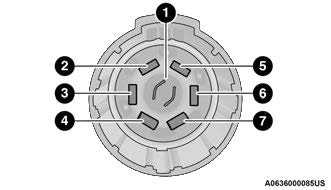 Seven-Pin Connector
 - Backup Lamps
- Running Lamps
- Left Stop/Turn
- Ground
- Battery
- Right Stop/Turn
- Electric Brakes
TOWING TIPS
Before towing, practice turning, stopping, and backing up the trailer in an area located away from heavy traffic.
Automatic Transmission
Select the DRIVE (D) range when towing. The transmission controls include a drive strategy to avoid frequent shifting when towing. However, if frequent shifting does occur while in DRIVE, you can use the AutoStick shift control to manually select a lower gear.
If equipped with Tow N Go, it is recommended to place the vehicle in tow mode by pushing the TOW button.
NOTE:
Using a lower gear while operating the vehicle under heavy loading conditions, will improve performance and extend transmission life by reducing excessive shifting and heat buildup. This action will also provide better engine braking.
AutoStick
- When using the AutoStick shift control, select the highest gear that allows for adequate performance and avoids frequent downshifts. For example, choose “5” if the desired speed can be maintained. Choose “4” or “3” if needed to maintain the desired speed.
- To prevent excess heat generation, avoid continuous driving at high RPM. Reduce vehicle speed as necessary to avoid extended driving at high RPM. Return to a higher gear or vehicle speed when grade and road conditions allow.
Cruise Control — If Equipped
- Do not use on hilly terrain or with heavy loads.
- When using the Cruise Control, if you experience speed drops greater than 10 mph (16 km/h), disengage until you can get back to cruising speed.
- Use Cruise Control in flat terrain and with light loads to maximize fuel efficiency.
RECREATIONAL TOWING (BEHIND MOTORHOME)
TOWING THIS VEHICLE BEHIND ANOTHER VEHICLE
| Towing Condition | Wheels OFF The Ground | Rear-Wheel Drive Models | All-Wheel Drive Models With Single-Speed Transfer Case | All-Wheel Drive Models With Two-Speed Transfer Case |
| Flat Tow |
NONE |
NOT ALLOWED |
NOT ALLOWED |
|
| Dolly Tow | Front | NOT ALLOWED | NOT ALLOWED | NOT ALLOWED |
| Rear | OK | NOT ALLOWED | NOT ALLOWED | |
| On Trailer | ALL | OK | OK | OK |
NOTE:
- When towing your vehicle, always follow applicable state and provincial laws. Contact state and provincial Highway Safety offices for additional details.
A flat tow electric power steering enable kit is available for increased flat tow performance, contact an authorized dealer for further details.
RECREATIONAL TOWING — REAR-WHEEL DRIVE MODELS
DO NOT flat tow this vehicle. Damage to the drivetrain will result.
Recreational towing (for two-wheel drive models) is allowed ONLY if the rear wheels are OFF the ground. This may be accomplished using a tow dolly or vehicle trailer.
If using a tow dolly, follow this procedure:
- Properly secure the dolly to the tow vehicle, following the dolly manufacturer’s instructions.
- Drive the rear wheels onto the tow dolly.
- Firmly apply the parking brake. Shift the transmission into PARK.
- Turn the ignition OFF.
- Properly secure the rear wheels to the dolly, following the dolly manufacturer’s instructions.
- Install a suitable clamping device, designed for towing, to secure the front wheels in the straight position.
CAUTION!
Towing with the rear wheels on the ground will cause severe transmission damage. Damage from improper towing is not covered under the New Vehicle Limited Warranty.
RECREATIONAL TOWING — ALL-WHEEL DRIVE MODELS (SINGLE-SPEED TRANSFER CASE)
Recreational towing is not allowed. These models do not have a N (Neutral) position in the transfer case.
NOTE:
This vehicle may be towed on a flatbed or vehicle trailer provided all four wheels are OFF the ground.
CAUTION!
Towing this vehicle in violation of the above requirements can cause severe transmission and/or transfer case damage. Damage from improper towing is not covered under the New Vehicle Limited Warranty.
RECREATIONAL TOWING — ALL-WHEEL DRIVE MODELS (TWO-SPEED TRANSFER CASE)
The transfer case must be shifted into N (Neutral) and the transmission must be in PARK for recreational towing. The N (Neutral) selection button is adjacent to the transfer case selector switch. Shifts into and out of transfer case N (Neutral) can take place with the selector switch in any position. There is a Mopar® Flat Tow Harness kit available to enable the Electronic Power Steering (EPS) while flat towing the vehicle, to provide more front axle stability. See an authorized dealer for more information and installation.
NOTE:
If the Mopar® Flat Tow Harness kit is installed, the EPS will use power from the battery to keep the EPS powered during a flat tow. A battery charging system is recommended so that the battery is not depleted over a long trip.
CAUTION!
- DO NOT dolly tow any AWD vehicle. Towing with only one set of wheels on the ground (front or rear) will cause severe transmission and/or transfer case damage. Tow with all four wheels either ON the ground, or OFF the ground (using a vehicle trailer).
- Tow only in the forward direction. Towing this vehicle backwards can cause severe damage to the transfer case.
The transmission must be in PARK for recreational towing.
Before recreational towing, be certain that the transfer case is fully in N (Neutral) page 149. Otherwise, internal damage will result.
Towing this vehicle in violation of the above requirements can cause severe transmission and/or transfer case damage. Damage from improper towing is not covered under the New Vehicle Limited Warranty.
Do not use a bumper-mounted clamp-on tow bar on your vehicle. The bumper face bar will be damaged.
Shifting Into N (Neutral)
WARNING!
You or others could be injured or killed if you leave the vehicle unattended with the transfer case in the N (Neutral) position without first fully engaging the parking brake. The transfer case N (Neutral) position disengages both the front and rear driveshafts from the powertrain and will allow the vehicle to roll, even if the transmission is in PARK. The parking brake should always be applied when the driver is not in the vehicle.
Use the following procedure to prepare your vehicle for recreational towing.
CAUTION!
It is necessary to follow these steps to be certain that the transfer case is fully in N (Neutral) before recreational towing to prevent damage to internal parts.
- Bring the vehicle to a complete stop on level ground, with the engine running.
- Press and hold the brake pedal.
- Shift the transmission into NEUTRAL.
NOTE:- Steps 1 through 3 are requirements that must be met before pushing the N (Neutral) button, and must continue to be met until the shift has been completed. If any of these requirements are not met before pushing the N (Neutral) button or are no longer met during the shift, the N (Neutral) indicator light will flash continuously until all requirements are met or until the N
(Neutral) button is released. - The ignition must be in the ON/RUN mode for a shift to take place and for the position indicator lights to be operable. If the ignition is not in the ON/RUN mode, the shift will not take place and no position indicator lights will be on or flashing.
- A flashing N (Neutral) position indicator light indicates that shift requirements have not been met.
- Steps 1 through 3 are requirements that must be met before pushing the N (Neutral) button, and must continue to be met until the shift has been completed. If any of these requirements are not met before pushing the N (Neutral) button or are no longer met during the shift, the N (Neutral) indicator light will flash continuously until all requirements are met or until the N
- Using a ballpoint pen or similar object, push and hold the recessed transfer case N (Neutral) button (located by the selector switch) for four seconds. The light behind the N symbol will blink, indicating shift in progress. The light will stop blinking (stay on solid) when the shift to N (Neutral) is complete. A “FOUR WHEEL DRIVE SYSTEM IN NEUTRAL” message will appear in the instrument cluster.
 N (Neutral) Button
 - After the shift is completed and the N (Neutral) light stays on, release the N (Neutral) button.
- Shift the transmission into REVERSE or DRIVE.
- Release the brake pedal for five seconds and ensure that there is no vehicle movement.
- Press and hold the brake pedal. Shift the transmission back into NEUTRAL.
- Firmly apply the parking brake.
- With the transmission and transfer case in NEUTRAL, push and hold the ENGINE START/STOP button until the engine turns off.
- Place the transmission gear selector in PARK. Release the brake pedal.
- Push the ENGINE START/STOP button twice (without pressing the brake pedal) to turn the ignition to the OFF mode.
CAUTION!
Damage to the transmission may occur if the transmission is shifted into PARK with the transfer case in N (Neutral) and the engine running. With the transfer case in N (Neutral) ensure that the engine is OFF before shifting the transmission into PARK. - Attach the vehicle to the tow vehicle using a suitable tow bar.
- Release the parking brake.
Shifting Out Of N (Neutral)
Use the following procedure to prepare your vehicle for normal usage.
- Bring the vehicle to a complete stop, leaving it connected to the tow vehicle.
- Firmly apply the parking brake.
- Start the engine.
- Press and hold the brake pedal.
- Shift the transmission into NEUTRAL.
NOTE:- Steps 1 through 5 are requirements that must be met before pushing the N (Neutral) button, and must continue to be met until the shift has been completed. If any of these requirements are not met before pushing the N (Neutral) button or are no longer met during the shift, the N (Neutral) indicator light will flash continuously until all requirements are met or until the N (Neutral) button is released.
- The ignition must be in the ON/RUN mode for a shift to take place and for the position indicator lights to be operable. If the ignition is not in the ON/RUN mode, the shift will not take place and no position indicator lights will be on or flashing.
- A flashing N (Neutral) position indicator light indicates that shift requirements have not been met.
- Using a ballpoint pen or similar object, push and hold the recessed transfer case N (Neutral) button (located by the selector switch) for one second.
 N (Neutral) Button
 - When the N (Neutral) indicator light turns off, release the N (Neutral) button.
- After the N (Neutral) button has been released, the transfer case will shift to the position indicated by the selector switch.
- Shift the transmission into PARK and turn the engine off.
- Release the brake pedal.
- Disconnect vehicle from the tow vehicle.
- Start the engine.
- Press and hold the brake pedal.
- Release the parking brake.
- Shift the transmission into REVERSE or DRIVE, release the brake pedal, and check that the vehicle operates normally.
DRIVING TIPS
ON-ROAD DRIVING TIPS
Utility vehicles have higher ground clearance and a narrower track to make them capable of performing in a wide variety of off-road applications. Specific design characteristics give them a higher center of gravity than conventional passenger cars.
An advantage of the higher ground clearance is a better view of the road, allowing you to anticipate problems. They are not designed for cornering at the same speeds as conventional passenger cars any more than sports cars are designed to perform satisfactorily in off-road conditions. Avoid sharp turns or abrupt maneuvers. As with other vehicles of this type, failure to operate this vehicle correctly may result in loss of control or vehicle rollover.
OFF-ROAD DRIVING TIPS
When To Use 4WD Low — If Equipped
When off-road driving, shift to 4WD Low for additional traction. This range should be limited to extreme situations such as deep snow, mud, or sand where additional low speed pulling power is needed. Vehicle speeds in excess of 25 mph (40 km/h) should be avoided when in 4WD Low.
WARNING!
Do not drive in 4WD Low on dry pavement; driveline damage may result. 4WD Low locks front and rear drivelines together and does not allow for differential action between the front to rear driveshafts. Driving in 4WD Low on pavement will cause driveline binding; use only on wet or slippery surfaces.
Driving Through Water
Although your vehicle is capable of driving through water, there are a number of precautions that must be considered before entering the water.
CAUTION!
When driving through water, do not exceed 5 mph (8 km/h). Always check water depth before entering as a precaution, and check all fluids afterward. Driving through water may cause damage not covered by the New Vehicle Limited Warranty.
Driving through water more than a few inches/centimeters deep will require extra caution to ensure safety and prevent damage to your vehicle. If you must drive through water, try to determine the depth and the bottom condition (and location of any obstacles) prior to entering. Proceed with caution and maintain a steady controlled speed less than 5 mph (8 km/h) in deep water to minimize wave effects.
Flowing Water
If the water is swift flowing and rising (as in storm run-off), avoid crossing until the water level recedes and/or the flow rate is reduced. If you must cross flowing water avoid depths in excess of 9 inches (23 cm). The flowing water can erode the streambed, causing your vehicle to sink into deeper water. Determine exit point(s) that are downstream of your entry point to allow for drifting.
Standing Water
Avoid driving in standing water deeper than
20 inches (51 cm), and reduce speed appropriately to minimize wave effects. Maximum speed in 20 inches (51 cm) of water is less than 5 mph (8 km/h).
Maintenance
After driving through deep water, inspect your vehicle fluids and lubricants (engine oil, transmission oil, axle, transfer case) to ensure the fluids have not been contaminated. Contaminated fluid (milky, foamy in appearance) should be flushed/changed as soon as possible to prevent component damage.
Driving In Snow, Mud And Sand
In heavy snow, when pulling a load, or for additional control at slower speeds, shift the transmission to a low gear and shift the transfer case to AWD Low if necessary Ú page 110. Only shift into a lower gear to maintain forward motion. Over-revving the engine can spin the wheels and traction will be lost.
Avoid abrupt downshifts on icy or slippery roads, because engine braking may cause skidding and loss of control.
Hill Climbing
NOTE:
Before attempting to climb a hill, determine the conditions at the crest and/or on the other side.
Before climbing a steep hill, shift the transmission to a lower gear and shift the transfer case to AWD Low. Use FIRST gear and AWD Low for very steep hills.
If you stall or begin to lose forward motion while climbing a steep hill, allow your vehicle to come to a stop and immediately apply the brakes. Restart the engine, and shift into REVERSE. Back slowly down the hill, allowing the compression braking of the engine to help regulate the speed. If the brakes are required to control vehicle speed, apply them lightly and avoid locking or skidding the tires.
WARNING!
If the engine stalls, you lose forward motion, or cannot make it to the top of a steep hill or grade, never attempt to turn around. To do so may result in tipping and rolling the vehicle. Always back carefully straight down a hill in REVERSE gear. Never back down a hill in NEUTRAL using only the brake.
Remember, never drive diagonally across a hill; always drive straight up or down.
If the wheels start to slip as you approach the crest of a hill, ease off the accelerator and maintain forward motion by turning the front wheels slowly. This may provide a fresh “bite” into the surface and will usually provide traction to complete the climb.
Traction Downhill
Shift the transmission into a low gear, and the transfer case into AWD Low. Let the vehicle go slowly down the hill with all four wheels turning against engine compression drag. This will permit you to control the vehicle speed and direction.
When descending mountains or hills, repeated braking can cause brake fade with loss of braking control. Avoid repeated heavy braking by downshifting the transmission whenever possible.
After Driving Off-Road
Off-road operation puts more stress on your vehicle than does most on-road driving. After going off-road, it is always a good idea to check for damage. That way you can get any problems taken care of right away and have your vehicle ready when you need it.
- Completely inspect the underbody of your vehicle. Check tires, body structure, steering, suspension, and exhaust system for damage.
- Inspect the radiator for mud and debris and clean as required.
- Check threaded fasteners for looseness, particularly on the chassis, drivetrain components, steering, and suspension. Retighten them, if required, and torque to the values specified in the Service Manual.
- Check for accumulations of plants or brush. These things could be a fire hazard. They might hide damage to fuel lines, brake hoses, axle pinion seals, and propeller shafts.
- After extended operation in mud, sand, water, or similar dirty conditions, have the radiator, fan, brake rotors, wheels, brake linings, and axle yokes inspected and cleaned as soon as possible.
WARNING!
Abrasive material in any part of the brakes may cause excessive wear or unpredictable braking. You might not have full braking power when you need it to prevent a collision. If you have been operating your vehicle in dirty conditions, get your brakes checked and cleaned as necessary.
- If you experience unusual vibration after driving in mud, slush or similar conditions, check the wheels for impacted material. Impacted mate-rial can cause a wheel imbalance and freeing the wheels of it will correct the situation.
2023 DODGE DURANGO Specs, Price, Features, Mileage (Brochure)
Reference Link
View Full PDF: Dodge Durango 2022 User Manual | Auto User Guide
Download Link: Owner’s Manuals & User Guides | Dodge