Jayco Alante 2023 Power Gear Below Floor Slideout System User Manual
Power Gear Below Floor Slideout System
Caution
- Always disconnect the battery from the system prior to the manually operating system. Failure to disconnect the battery can cause electricity to back feed through the motor and cause serious damage to the system as well as void the warranty.
- Use EXTREME CAUTION when extending/retracting the room using the manual override feature. The gears can be stripped out if the room is manually retracted/extended to its fullest extent and the operator continues to rotate manually override. Damage can also occur to the slide components, slide room structure, or trim components. Damages due to misuse of the manual override feature will void any and all claims to the Limited Warranty.
-
Jayco 2023 Top Accessories
[amalinkspro_table id=”32452″ new-window=”on” nofollow=”on” addtocart=”off” /]
Manual Override
The slideout system is equipped with a manual override that allows you to extend or retract the room in the event of a loss of power.
If the room does not move when the switch is pressed, check the following:
- Make sure the slideout system is turned on.
- The battery is fully charged and connected.
- Transit bars have been removed (if so equipped).
Warning
When the motor brake is disengaged the slideout room WILL NOT lock into place and will not be sealed. When the room has been manually retracted, be sure to install transit bars (if so equipped) and return the motor brake lever to its normal engaged position in order to seal and lock the room into position.
If the room still does not move when the switch is pressed, follow the steps below to manually override the slideout room:
- Turn the Main Power OFF. The override will not work if it has power going to it. Do not work on the system unless the battery is disconnected.
- Locate the slideout controller. There are two versions of the controller.
- Version 1, unplug the 6 pin wiring harness from the controller.
- Version 2, remove one of the motor leads, either the motor I or motor II lead from the controller.
- Locate the slideout motor (Fig. 1) mounted to one of the slideout rails. Some models may require removal of the underbelly or cover to access the motor. In a bedroom slideout, it may be located under the bed.
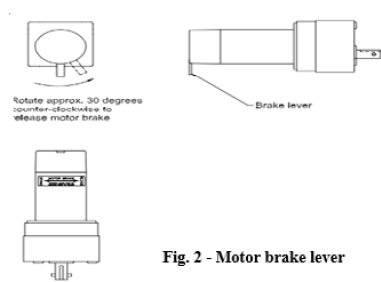
- Rotate the brake lever, on the backside of the motor, counter-clockwise (looking from the rear of the motor) about 1/8 of a turn to the released position. This will release the brake that holds the room in place.
- Locate the manual override for the slideout system (Fig. 1).
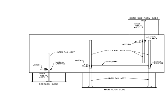
- The room is now free to move. Using either a 5/8” or 3/4” wrench or socket, crank the room either in or out completely. If the slideout system is supplied with a gearbox override (optional), use the crank handle to move the room.
- When the rooms is fully in or out have one person apply pressure to the wrench/ratchet and return the brake lever to its engaged position. This ensures the room is locked into a sealed position.
- Install the transit bars (if so equipped) o the slideout room and take the unit to an authorized dealer for service.
Refer to the Power Gear® Electric Slideout Operation Manual for detailed operation, safety and troubleshooting information.
Power Gear Ram Slideout System Manual Override Procedure
The system has been equipped with 3/4” hex
override couplers located on the drive component of the system. Due to the size and weight of some rooms, assistance may be needed to push the room in.
Use the following steps to mechanically operate the room
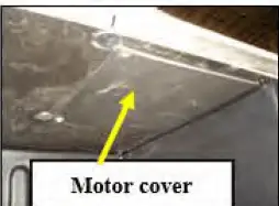
- Locate the ABS motor access cover for the slideout.
This cover will be located inside one of the storage compartments under the slide room up at the top of the compartment. - Remove (4) screws holding the panel to the top of the compartment. Remove the cover.
- Unplug the motor leads at the connector. Gray connector with red and black wires.
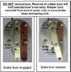
- To release the motor brake you must depress the spring lock lever, which then allows you to pivot the brake lever, which in turn releases the brake. These parts are located inside the rubber boot wire tied over the motor. You must manipulate these parts without removing the rubber boot. As noted on the side-by-side photo, removing this boot will void your motor warranty.
These photos will help you figure out how this works.
The side-by-side photo (below) shows the spring lock lever and the brake lever.
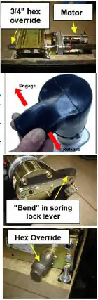
- The spring lock lever is a thin metal arm with a slight bend at the end, which will hold the brake lever in the released position.
- The brake lever is the heavier thicker metal arm with a hole in the end.
- The normal position for these two levers is to be parallel to each other as shown in the first side-by-side photo.
The motor brake is engaged with levers side by side. - The brake lever is moveable; the spring lock lever is not moveable. To release the brake lever, you must push the bent end of the spring lock lever away from the brake lever; this will allow you to pivot the brake lever so it moves over on top of the spring lock lever. The bent end will hold the brake lever in the released position. (photo shows this “bend”).
- Once the brake motor is released, you will need to remove the skirting on the side of the slideout floor where the hex override is located.
- Use a ratchet with a 3/4” socket (or wrench) to turn the hex override and manually move the slideout.
- When the slideout is retracted, check to make sure you have a good seal, and re-place the skirting on the slideout.
- Return the brake release lever back to the “engaged” position (parallel to the spring lock lever). Pressing the bent end of the spring lock lever will allow the brake lever to be moved.
- Plug the motor connector back in again.
- Replace the plastic motor cover with the (4) screws removed previously.
- Take the unit to an authorized dealer for service.
For further information, refer to the manufacturer’s owner’s manual.
[amalinkspro_table id=”32446″ new-window=”on” nofollow=”on” addtocart=”off” /]
Reference Links
View Full User Guide: Jayco Alante 2023 User Manual
Download Manuals: https://www.jayco.com/manuals
Jayco 2023 Top Accessories
[amalinkspro_table id=”32452″ new-window=”on” nofollow=”on” addtocart=”off” /]