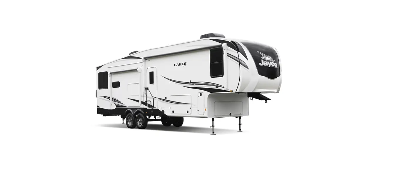
Jayco Eagle Fifth Wheels 2023 Operating the Slideout User Manual
Operating the Slideout
The slideout will not function until the stops are properly set or faults are cleared. A solid “ON” GREEN LED indicates room movement.
The RED LED indicates a fault or a problem with the system. (Refer to the Fault Diagnostics / Troubleshooting).
Prior to moving the slideout room set the parking brake.
To ensure ample voltage is being supplied to the slideout system motor, power should be supplied from one of the following sources:
- Attach the RV to shore power.
- Have the motor home engine running.
- Turn on the generator.
Extending/retracting the room
- Engine or generator must be running, or plugged into shore power.
- Transmission must be in park or neutral (if applicable).
- Set the parking brake and level the unit.
- Remove transit bars (if so equipped) if extending the room; install if retracting.
- Turn ON the on/off switch or key.
- Press and hold the OUT button. To retract, press and hold the IN button. There will be a slight delay before the room begins moving.
- The GREEN LED should be solid ON when room is in motion.
- Release the OUT button when the room is fully extended or the IN button when fully retracted, and stops moving.
- Turn OFF the on/off switch or key.
Fault Diagnostics / Troubleshooting
The control has the ability to detect and display several faults. When a fault is detected, room movement stops and two different LEDs will flash in a pattern.
The RED FAULT CODE LED will flash a number of times corresponding to a specific fault code (refer to the Fault Code Chart).
The GREEN ROOM MOVEMENT LED will flash GREEN a number of times corresponding to which motor has the associated fault.
Example: (4) RED flashes and (2) GREEN flashes indicate a motor fault on motor 2.
MAJOR and MINOR faults; faults must be cleared for the room to operate normally.
- MINOR faults can be cleared by pushing and releasing the IN or OUT buttons on the wall touchpad.
- MAJOR faults must be cleared by pushing and releasing the SET STOPS/CLEAR FAULTS button located on the back of the wall touchpad.
NOTE:
For MAJOR faults, the control must be overridden by following the EMERGENCY RETRACT MODE in the OVERRIDE MODES section.
| Fault Code | Fault Type | Fault Codes | ||
| Description | Possible Cause | Possible Solution | ||
|
1 |
Major |
Stops not programmed |
|
Steps need to be pro grammed by an authorized service facility. |
|
2 |
Minor |
System Fault |
|
Run room in opposite direction. If it continues to move in the opposite direction, remove obstruction, excessive weight in room or repair of damaged component. If room stops moving in opposite direction, observe fault code and refer to this chart |
|
4 |
Major |
Excessive Battery Voltage |
|
|
|
Park brake LED flashing |
|
|
||
|
6 |
Minor |
Supply voltage to control box is 17 0 V DC or greater |
Check 2-pin power connector at control box. If the voltage is 17. VDC or higher, contact
O.E.M for power and ground supplies |
| Park brake LED flashing |
|
|
| Low voltage LED flashing | Incoming violated to control box is below
12.0 VDC |
Check 2-pin power connector at control box. If voltage is below 12.0 VDC contact
O.E.M for power and ground supplies. |
Preventative Maintenance
The Power Gear® slideout system requires very little maintenance. Read and follow these procedures:
- When the room is extended, visually inspect the slide rail assemblies. Check for the excess buildup of dirt or foreign material; remove any debris that may be present.
- If the system squeaks or makes any noises, blow out any debris from the gear rack arms and apply a dry lubricant to prevent and/or stop squeaking.
Refer to the Power Gear® website www.powergearus.com for additional information.
Override Modes
In the event of component failure or loss of system power, your slideout can be manually overridden and retracted for travel.
- NOTE:
During the override procedure, the unit will exit this mode if the room has not been moved for two (2) minutes or if a fault is detected during room movement. The Fault Code (RED) and Room or Lock Movement (GREEN) LEDs will flash rapidly for 10 seconds to indicate the override procedure failed. After 10 seconds of flashing, the control will automatically default to FAULT CODE 1. Programming must be restarted. - NOTE
After overriding the system, the room control will need to be re-programmed by an OEM-authorized dealer.
[amalinkspro_table id=”32452″ new-window=”on” nofollow=”on” addtocart=”off” /]
Reference Links
View Full User Guide: Jayco Eagle Fifth Wheels 2023 User Manual
Download Manuals: https://www.jayco.com/manuals


