Jayco Eagle Fifth Wheels 2023 User Manual
Jayco Eagle Fifth Wheels 2023 Introduction User Manual
Introduction
Congratulations! On your Jayco recreation vehicle purchase. We are excited to welcome you to our growing RV family. We are committed to being the most respected name in RVs. Jayco recreation vehicles are manufactured for use as temporary living quarters for recreation, camping, and travel uses, all as defined by the bylaws of the Recreation Vehicle Industry Association (RVIA). This recreation vehicle is not intended for use as a full-time residence or for commercial use. Commercial use means using the recreation vehicle as a business asset such as a mobile office or using the recreation vehicle for lease or rental purposes.
Jayco reserves the right to discontinue or change specifications or design at any time without notice and without incurring any obligation whatsoever. Recreation vehicles built for sale in Canada may differ to conform to Canadian Codes. We invite you to drop by our Visitors Center located in Middlebury, Indiana. To book a factory tour or check on available tour times, log on to https://www.jayco.com and click on the ABOUT heading. Select “Visit Us” from the drop-down for factory tour information.
Options and Equipment
Jayco recreation vehicles are available in several sizes and models, so accessories and components may differ slightly between models. Some equipment described in this manual may not apply to your recreation vehicle. Jayco reserves the right to discontinue or change specifications or design at any time without notice, and to make additions or improvements without incurring any obligations upon itself to install these changes on its products previously manufactured. Recreation vehicles built for sale in Canada may differ to conform to Canadian Codes.
Dealer Responsibility
At the time of the sale of the new recreation vehicle, your Jayco dealer is expected to:
- Deliver your recreation vehicle in the best condition possible. Your recreation vehicle must pass the dealer’s pre-delivery inspection (PDI), including all systems tests.
- Provide orientation of the motor home, its systems, components, and their operation (including a test drive). Request that you read all motorized warranty information and explain any provision not clearly understood.
- Complete and return the Warranty Registration and Customer Delivery form and the chassis manufacturer Chassis Manufacturer’s Delayed Warranty Start form to activate the applicable warranty coverage (mileage and date of purchase must be included on both forms). Retain copies of these forms in the motor home for any required warranty coverage as needed at home or while traveling.
- Ensure that you receive a complete Owner’s Portfolio and review the individual manufacturer’s limited warranty provisions with you. The dealer can assist in completing these forms and in locating any required component model or serial numbers.
The Limited Warranty is activated only after Jayco receives a signed and dated “Warranty Registration and Customer Delivery Form” from your dealer.
Customer Relations
Jayco has empowered its dealers to make warranty and repair decisions. If a special circumstance occurs that requires information from Jayco, we have asked your dealer’s service management to make the contact on your behalf. This is why you should always talk to your dealer’s service management first.
Please provide the following information when contacting us for assistance:
- Customer name and current location.
- Phone number where you can be reached.
- 17-digit chassis Vehicle Identification Number (VIN) or 9-digit Serial.
- The current vehicle mileage.
- Your date of purchase.
- If applicable, the component description, serial number, and model number.
- A detailed description of the concern.
- The name of your selling dealer.
- If different from above, the contact information for the RV repair facility you are contacting Jayco to discuss.
Read all instructions for Introduction User Manual
Jayco Eagle Fifth Wheels 2023 Emergency Warranty Repair User Manual
Jayco Eagle Fifth Wheels 2023 Emergency Warranty Repair User Manual
Obtaining Emergency Warranty Repair
- Call 800-283-8267 or use our website dealer locator to find an authorized Jayco dealer in your area. Contact them for an appointment; they will handle all warranty repair billing and returned parts for you.
- If you cannot locate an authorized Jayco dealer near you, ask the campground staff for referrals or check the internet. Or contact Jayco Customer Service or your selling dealer for assistance in locating a repair facility.
- Contact the RV repair facility to discuss your situation and make an appointment. Ask how their billing will be handled. They may choose to bill Jayco directly; otherwise, you are expected to pay them.
- Have the RV repair facility inspect your RV. Either they or you must call Jayco Customer Service to discuss applicable warranty coverage prior to any repair work being performed.
- Jayco Customer Service will issue an authorization number upon warranty repair approval and advise if any original parts need to be returned.
- Once Jayco Customer Service has issued an authorization number, the RV repair facility may begin actual repair to your RV.
- Inspect the completed repair work thoroughly. If you are not satisfied, communicate that immediately to the RV repair facility management. Make sure you are satisfied with the repair before you pay or leave the premises.
- For reimbursement, either you or the RV repair facility must send a copy of your itemized repair bill and all requested returned parts by UPS (regular ground, freight pre-paid) within 60 days of the completed repair date.
To expedite the processing of your warranty claim, including your name, address, phone number, RV 17-digit VIN, and authorization number. If returning parts include a copy of your return freight bill.
Obtaining weekend or after-business-hours repair assistance
If an authorized Jayco dealer is not located nearby, contact your selling dealer for assistance. If your dealer is closed, check with the campground staff or the internet for an RV repair facility. Have the item repaired and contact Jayco Customer Service immediately the following business day. Failure to contact Jayco Customer Service, unauthorized or improper warranty repairs, or failure to return requested original parts may result in loss of reimbursements and/or loss of warranty.
To Contact Us
Mailing address
Jayco, Inc. Customer Service
P.O. Box 460
903 S. Main Street Middlebury IN 46540 Phone (toll-free) Phone (local)
Fax (toll-free) Brochure request Parts email
Service email Website
Shipping address
Jayco, Inc. Customer Service 100 Bontrager Drive Bldg 42 Door 4220 Middlebury IN 46540 800-283-8267
574-825-0608
866-709-9139
info@Jayco.com
parts@Jayco.com
service@Jayco.com
www.Jayco.com
We welcome you to join our online community by following and engaging with us on our various social media pages.
Read all instructions for Emergency Warranty Repair User Manual
Jayco Eagle Fifth Wheels 2023 Safety Alerts User Manual
Safety Alerts
Throughout this manual, certain items are labeled NOTE, NOTICE, CAUTION, WARNING, and DANGER. These terms will alert you to precautions that can involve risk to your vehicle or to your personal safety. Read and follow them carefully. National Safety Associations and organizations require many of the instructions listed. Always use the appropriate safety gear when servicing or maintaining your recreation vehicle. Please call your dealer or our customer service representatives if you are unsure how to proceed.
These signal words indicate precautions and potential situations, which if not avoided, may result in personal injury, property damage, or damage to your recreation vehicle. These pre-cautions are listed in the appropriate areas in this Owner’s Manual, in the information contained in the Warranty Packet, and on safety labels affixed to your recreation vehicle. Read and follow them carefully.
NOTE:
Gives helpful information
This is the safety alert symbol. It is used to alert you to potential personal injury hazards. Obey all safety messages that follow this symbol to avoid possible injury or death.
Note
Indicates a potential situation that, if not avoided, may result in property damage or damage to your RV.
Cauti0n
Indicates a potentially hazardous situation that, if not avoided, may result in minor or moderate injury. It may also be used to alert against unsafe practices.
Danger
Indicates an imminently hazardous situation that, if not avoided, will result in death or serious injury. This alert information is limited to the most extreme situations.
Warning
Indicates a potentially hazardous situation that, if not avoided, may result in death or serious injury.
Reporting Safety Defects
In the United States:
If you believe that your recreation vehicle has an alleged defect that could cause a crash or cause injury or death, you should immediately inform the National Highway Traffic Safety Administration (NHTSA), in addition to notifying our Customer Service Department.
If NHTSA receives similar complaints, it may open an investigation, and if it finds that a safety defect exists in a group of vehicles, it may order a recall and remedy campaign. However, NHTSA cannot become involved in individual problems between you, your dealer, or your vehicle manufacturer. For additional information, please refer to the NHTSA website at www.safercar.gov.
Read all instructions for Safety Alerts User Manual
Jayco Eagle Fifth Wheels 2023 Obtaining Service User Manual
Obtaining Service At Our Customer
Should your recreation vehicle be in need of service, and your dealer recommends that the repairs be made at our Customer Service facility, your recreation vehicle may be returned to us with the following guidelines.
- You or your dealer must make a confirmed appointment 60 days prior to dropping off the recreation vehicle at our Customer Service facility.
- The holding tanks must be emptied and rinsed. We have a dumping station available for customer use.
- The propane system (if so equipped) and all electrical systems must be shut down and turned off. We are not responsible for discharged batteries or propane tanks.
- During the appropriate season, please ensure the RV has been winterized.
- Unless prior approval has been obtained from our Customer Service facility, all personal items must be removed from the area where you are requesting service repair and the refrigerator emptied. We are not responsible for the loss of food items.
- All transportation costs are the responsibility of the owner. You may need to arrange for alternative accommodations for some types of repairs. Please be prepared accordingly.
Our Customer Service facility occasionally utilizes local independent repair facilities. Your vehicle may be referred to or repaired by one of these local repair facilities.
Obtaining Service For Separately Warranted Items
Your selling dealer is responsible for servicing your recreation vehicle before delivery and has an interest in your continued satisfaction. We recommend your dealer perform all inspection, warranty, and maintenance services. Some dealers may be authorized service centers for those OEMs whose products are warranted separately and excluded from the Limited Warranty.
Parts and Accessories
Contact your authorized dealer for assistance in obtaining replacement parts or accessories. We do not sell directly to retail or non-authorized dealers. If the original part is no longer available, we will make every effort to provide an appropriate substitute.
2023 Jayco Limited Warranty Pinnacle, North Point, Eagle, and Seismic
WHAT AND WHO IS COVERED
This Limited Warranty covers only Jayco Pinnacle, North Point, Eagle, and Seismic brand recreational vehicles sold in, and that remain in, the United States, U.S. Territories and Canada and used for the intended purpose of recreational travel and camping. If a substantial defect in material or workmanship, attributable to Jayco, is found to exist and is reported to Jayco or an authorized servicing dealer during the applicable warranty period, it will be repaired or replaced, at Jayco’s option, without charge to the RV owner, in accordance with the terms, conditions, and limitations of this limited warranty.
This limited warranty applies to the first consumer purchaser of a new RV only. All rights and limitations within this warranty are applicable to the original owner of the RV only. You may contact an independent, authorized dealer for details. Jayco’s obligation to repair or replace defective materials or workmanship is the sole obligation of Jayco under this limited warranty. Jayco reserves the right to use new or remanufactured parts of similar quality to complete any work, and to make parts and design changes from time to time without notice to anyone. Jayco reserves the right to make changes in the design or material of its products without incurring any obligation to incorporate such changes in any product previously manufactured. Jayco makes no warranty as to the future performance of this RV, and this limited warranty is not intended to extend to the future performance of this RV, or any of its materials, components or parts. In addition, the RV owner’s obligation to notify Jayco, or one of its independent, authorized dealers, of a claimed defect does not modify any obligation placed on the RV owner to contact Jayco directly when attempting to pursue remedies under state or federal law.
LIMITATIONS, EXCLUSIONS AND DISCLAIMER OF IMPLIED WARRANTIES: ANY IMPLIED WARRANTY THAT IS FOUND TO ARISE BY WAY OF STATE OR FEDERAL LAW, INCLUDING ANY IMPLIED WARRANTY OF MERCHANTABILITY OR ANY IMPLIED WARRANTY OF FITNESS, IS LIMITED IN DURATION TO THE DURATION SET FORTH IN THIS LIMITED WARRANTY AND IS LIMITED IN SCOPE OF COVERAGE TO THE SCOPE OF COVERAGE OF THIS LIMITED WARRANTY. ALL IMPLIED WARRANTIES AND CONDITIONS, STATUTORY OR OTHERWISE, ARE DISCLAIMED IN THEIR ENTIRETY AS TO RVs OR COMPONENTS OF RVs EXCLUDED OR NOT COVERED UNDER THIS WARRANTY.
Read all instructions for Obtaining Service User Manual
Jayco Eagle Fifth Wheels 2023 PERIOD OF COVERAGE User Manual
Jayco Eagle Fifth Wheels 2023 PERIOD OF COVERAGE User Manual
THE PERIOD OF COVERAGE
The duration of this Limited Warranty is 2 years. The warranty period begins on the date that the RV is delivered to the first retail purchaser by an independent, authorized dealer of Jayco, or, if the dealer places the vehicle in service before retail sale, on the date the RV is first placed in such service. The term of this Limited Warranty is 3 years for substantial defects to any “Structure Components”. Structure Components means materials and/or workmanship directly attributable to Jayco relating to the lamination of the fiberglass sidewall assembly, the lamination of the rear wall assembly, the lamination of the fiberglass front wall (wrap) assembly, sidewall/end wall/front and rear wall frame assembly (wood and aluminum), roof frame assembly (wood and aluminum), and floor frame assembly (wood and aluminum). Structure Components specifically excludes front and rear fiberglass caps and any other cosmetic fiberglass attachments, sidewall metal (unless the root cause is the wall structure); exterior roof material (EPDM rubber, TPO, etc.); floor covering (carpet, linoleum, hardwood tile, etc.); all side-wall, end wall, front and rear wall, roof and floor attachments, and delamination caused by water intrusion from lack of required exterior seal maintenance or other maintenance. Structure Components further excludes all items identified under “What is Not Covered” below.
Jayco reserves the right to have new or remanufactured parts of similar quality used to complete any work, and to make parts and design changes from time to time without notice to anyone. Jayco reserves the right to make changes in the design or material of its products without incurring any obligation to incorporate such changes in any product previously manufactured. Jayco makes no warranty as to the future performance of this RV, and this limited warranty is not intended to extend to the future performance of this RV, or any of its materials, components or parts. In addition, the RV owner’s obligation to notify Jayco, or one of its independent, authorized dealers, of a claimed defect does not modify any obligation placed on the RV owner to contact Jayco directly when attempting to pursue remedies under state or federal law.
HOW TO GET SERVICE
It is normal to expect some warranty service during the term of this Limited Warranty.
To obtain warranty service the owner must do all of the following:
- Notify an independent, authorized dealer of Jayco, or Jayco, of the substantial defect in material or workmanship attributable to Jayco, within the warranty coverage period designated above;
- Provide the notification mentioned in (1), above, within ten (10) days of when the owner discovered or should have discovered, the substantial defect in material or workmanship attributable to Jayco;
- Promptly schedule an appointment with and take the RV to an independent, authorized dealer of Jayco, or Jayco, for repairs; and
- Pay any freight or transportation costs, import duties, fees, and all incidental expenses associated with obtaining warranty service.
If you need assistance, you may contact Jayco, at 903 S. Main Street, P.O. Box 460, Middle-bury, Indiana 46540, Attn: Customer Service, (800) 283-8267.
NOTE: Jayco does not control the scheduling of service work at independent, authorized dealerships. You may encounter some delay in scheduling or completion of work. Also, you must notify the selling dealer at time of delivery to have work performed on any defect that occurred at the factory during manufacture at no cost to you as provided by this limited war-ranty. (See below under WHAT IS NOT COVERED).
If two (2) or more service attempts have been made to correct any covered defect that you believe impairs the value, use or safety of the RV, or if it has taken longer than thirty (30) days for those types of repairs to be completed, you must, to the extent permitted by law, notify Jayco directly, in writing, at the above address, of the unsuccessful repair(s) of the alleged defect(s) so that Jayco can become directly involved in making sure that you are provided service pursuant to the terms of this limited warranty.
Jayco’s obligation is to address, within industry standards, any covered substantial defect discovered and reported within the warranty coverage period provided: (1) you notify Jayco or an authorized dealer within 10 days of your discovery of the substantial defect; AND (2) you deliver the RV to Jayco or an authorized dealership at your cost and expense. If this primary remedy fails to successfully cure any substantial defect after a reasonable number of repair attempts, your sole and exclusive remedy shall be to have Jayco pay an independent service shop of your choice to perform repairs to the substantial defect. If the substantial defect is incapable of being repaired, your exclusive remedy will be to receive diminished value damages (i.e. the difference in your purchase price and the actual value of the RV on the date of purchase due to the substantial defect that is incapable of repair). You must exhaust the primary repair remedy and this back-up remedy and both these remedies must fail of their essential purpose before initiating any action against Jayco.
Read all instructions for PERIOD OF COVERAGE User Manual
Jayco Eagle Fifth Wheels 2023 WHAT IS NOT COVERED User Manual
Jayco Eagle Fifth Wheels 2023 WHAT IS NOT COVERED User Manual
WHAT IS NOT COVERED
By way of example only, this limited warranty does not cover any of the following:
- Defects in materials, components or parts of the structure of the RV not attributable to Jayco;
- Items that are added or changed after the RV leaves the possession of Jayco;
- Additional equipment or accessories installed at any dealership, or other place of business, or by any other party, other than Jayco;
- Any RV used for rental or other business or commercial purposes (Note: It shall be concluded that the RV has been used for commercial and/or business purposes if the RV owner or user files a tax form claiming any business or commercial tax benefit related to the RV, or if the RV is purchased, registered or titled in a business name or any business association such as a corporation or limited liability company);
- Any RV sold or used outside the United States, U.S. Territories or Canada;
- Any RV not used solely for recreational travel and camping;
- Any RV purchased through auction or wholesale;
- Any RV purchased from a dealer that is not an authorized dealer of Jayco;
- Any defect arising from excess weight placed on the Structural Components;
- Normal wear, tear or usage, such as tears, punctures, soiling, mildew, fading, or discoloration of exterior plastic or fiberglass, or soft goods, such as upholstery, drapes, carpet, vinyl, screens, cushions, mattresses and fabrics;
- The effects of condensation or moisture from condensation inside or outside the RV;
- mold or any damage caused by mold to the inside or outside of the RV;
- imperfections that do not affect the suitability of the RV for its intended purpose of recreational use or items that are working as designed but that you are unhappy with;
- exterior paint or finish;
- problems, including water leaks, related to misuse, mishandling, neglect or abuse, including failure to maintain the RV in accordance with the owner’s manual, or other routine maintenance such as inspections, lubricating, adjustments, tightening of screws and fittings, tightening of lug nuts, sealing, rotating tires;
- Damage due to accident, whether or not foreseeable, including any acts of weather;
- Damage, rust, or corrosion due to the environment, theft, vandalism, fire, or other intervening acts not attributable to Jayco;
- Damage caused by unregulated water pressure, tank overfill, or plumbing system modifications resulting in flooding of the vehicle;
- Failure of the original retail purchaser or others to follow ordinary maintenance procedures as recommended by Jayco;
- Damage caused by unprotected electrical hook-ups (home or campground), power surges, lightning, circuit overload, or electrical system modifications;
- Damage resulting from tire wear or tire failure;
- Hydraulic leveling jacks or leveling system;
- Defacing, scratches, dents, and chips on any surface or fabric of the RV; damage caused by an infestation by insects or animals;
- Damage caused by off-road use, overloading the RV, or alteration of the RV, or any of its components or parts;
- Wheel alignment or adjustments to axles when caused by improper maintenance, loading or damage from road hazards, including off-road travel, wheel damage or balancing or damage from tire failures;
- Any costs associated with obtaining service, including by way of example, travel costs, are specifically excluded from the coverage of this warranty; and
- Any component, system, or part of the RV that is warranted by another entity, including, by way of example, handling, braking, wheel balance, tires, tubes, batteries, gauges, generator, awning, hydraulic jacks, inverter, converter, microwave, television, DVD/CD player, radio, speakers, television, refrigerator, range, hot water heater, water pump, stove, carbon monoxide detector, smoke detector, propane detector, furnace or any air conditioner. The written warranty provided by any manufacturer of the component part is the direct responsibility of that manufacturer. Defects and/or damage to interior and exterior surfaces, trim, upholstery and other appearance items may occur at the factory. These items are usually detected and corrected at the factory or by the selling dealer prior to delivery to the retail customer. You must inspect your RV for this type of damage when you take delivery. If you find any such defect or damage you must notify the selling dealer at time of delivery to have these items covered by this limited warranty and to have work performed on the items at no cost to you as provided by this limited warranty.
EVENTS DISCHARGING JAYCO FROM OBLIGATION UNDER WARRANTY
Certain things completely discharge Jayco from any obligation under this warranty and void it. By way of example, the following shall discharge Jayco from any express or implied warranty obligation to repair or replace any defect that results from: any rental or other business or commercial use or purchase of the RV (as defined in this warranty), any RV titled or registered in the name of any business or business association (such as a corporation or limited liability company), any RV sold outside of, or used outside of, the United States, U.S. Territories or Canada, through an auction or wholesale or by a non-authorized dealer, any defect in a separately manufactured component part, owner neglect or failure to provide routine maintenance (See Owner’s Manual), unauthorized alteration, off road use, collision or accident, whether or not foreseeable, including any acts of weather or damage or corrosion due to the environment, theft, vandalism, fire, explosions, overloading in excess of weight ratings, and tampering with any portion of the RV, or any use of the RV as a semi-permanent or permanent home.
Read all instructions for WHAT IS NOT COVERED User Manual
Jayco 2023 Top Accessories
[amalinkspro_table id=”32452″ new-window=”on” nofollow=”on” addtocart=”off” /]
Jayco Eagle Fifth Wheels 2023 LEGAL REMEDIES User Manual
LEGAL REMEDIES
ANY ACTION TO ENFORCE ANY PORTION OF THIS LIMITED WARRANTY, OR ANY IMPLIED WARRANTY, MUST BE COMMENCED WITHIN NINETY (90) DAYS AFTER THE EXPIRATION OF THE WARRANTY COVERAGE PERIOD DESIGNATED ABOVE. Any performance of repairs shall not suspend this limitation period from expiring unless state law provides otherwise. Any performance of repairs after the warranty coverage period has expired, or performance of repairs regarding anything excluded from coverage under this limited warranty shall be considered “goodwill” repairs, and they will not alter the express terms of this limited warranty, or extend the warranty coverage period or this limitation period. In addition, this warranty is not intended to extend to future performance, and nothing in this warranty, or any action of Jayco, or any agent of Jayco, shall be interpreted as an extension of the warranty period or this limitation period. Some states do not allow a reduction in the statute of limitations, so this reduction may not apply to you. Jayco is not required to notify you if authorized repairs are considered “goodwill” by Jayco.
WARRANTY REGISTRATIONS
Your warranty registration records should be completed and delivered to the manufacturers of component parts. The selling dealership will assist you in completing and submitting the Jayco product warranty registration form. That form must be returned to Jayco within ten (10) days of your taking delivery of the RV. Your Jayco warranty will not be registered unless this warranty registration is completed and received by Jayco. Failure to file this warranty registration with Jayco will not affect your rights under this limited warranty as long as you can present proof of purchase, but it can cause delays in obtaining the benefits of this limited warranty, and it may inhibit any servicing facility’s ability to provide proper repairs and/or part replacement. Note, tender, and acceptance of a warranty registration do not alter the express terms of this limited warranty or any of its exclusions.
CARE AND MAINTENANCE
It is the owner’s responsibility to perform proper care and maintenance of the RV and to assure correct load distribution. For details regarding this, please see your Jayco owner’s manual and the owner’s manuals of the chassis manufacturer and other component part manufacturers. These outline various care and maintenance that is required to maintain your RV. Please review all manuals supplied with your RV, and contact your selling dealership or supplier of the component part if you have questions. Note: Failure to maintain the RV as noted in those manuals voids this limited warranty, and any damage to the RV as a result of your failure to perform such care, is not covered by this limited warranty.
THIS WARRANTY GIVES YOU SPECIFIC LEGAL RIGHTS, AND YOU MAY ALSO HAVE OTHER RIGHTS THAT VARY FROM STATE TO STATE.
ACCEPTANCE OF WARRANTY
When you request or accept the performance of repairs under the terms of this Limited Warranty, you are confirming the acceptance of all terms of this Limited Warranty, including, by way of example, warranty limitations and disclaimers, the forum selection clause, and the clause reducing the time period within which suit must be filed for breach.
LEGAL REMEDIES
EXCLUSIVE JURISDICTION FOR DECIDING LEGAL DISPUTES RELATING TO AN ALLEGED BREACH OF WARRANTY OR OTHERWISE RELATING TO YOUR PURCHASE OR OWNERSHIP OF THE RV MUST BE FILED IN THE COURTS WITHIN THE STATE OF INDIANA. THIS LIMITED WARRANTY SHALL BE INTERPRETED AND CONSTRUED IN ACCORDANCE WITH THE LAWS OF THE STATE OF INDI-ANA. THIS WARRANTY GIVES YOU SPECIFIC LEGAL RIGHTS, AND YOU MAY ALSO HAVE OTHER RIGHTS THAT VARY FROM STATE TO STATE OR PROVINCE TO PROVINCE. ALL ACTIONS OF ANY KIND RELATING TO THE RV SHALL BE DECIDED BY A JUDGE RATHER THAN A JURY.
Read all instructions for LEGAL REMEDIES User Manual
Jayco Eagle Fifth Wheels 2023 Secondary Means of Escape User Manual
Jayco Eagle Fifth Wheels 2023 Secondary Means of Escape User Manual
Secondary Means of Escape
Your recreation vehicle has been equipped with a window(s) that serves as a secondary means of escape. The window (s) will allow a quick exit from the vehicle during an emergency if access to the main entrance door is not available. It is easily identified by the red latches and labels.
Do not remove the EXIT window label from your RV
When parking your recreation vehicle, make sure the egress window is not blocked by trees or other obstacles. Make sure the ground below the window is solid and can be used as an escape path. Practice opening the window before an emergency occurs, and make sure all occupants know how to operate it.
Caution
Exercise care when opening the exit window. If opened too far, it may come off the hinge. This may result in damage to the unit or window.
NOTE:
All windows must be closed and locked while the RV is in transit. Your recreation vehicle may be equipped with one of the following exit window styles:
Flip latch style (2 per window)
- Push up on the front lip of the latch and the latch unfolds.
- Push up on the front lip of the latch again to unhook the latch from the window.
- When both latches are released, push out on the window which is hinged at the top. Exit the vehicle.
- The screen does not need to be removed from the window.
Slider window latch style
Pull the lever down to unlock the window.
Slide the window to the right to open and exit the vehicle. The screen does not need to be removed from the window.
Lever style latch
- Remove the screen by pulling the red tab (upper right arrow).
- Pull the lever out from the sash clamps.
- Swing the lever out so it is positioned straight out from the window.
- Push the lever (and window) out to open and exit the vehicle.
Fire Safety
If a fire does start, follow these basic safety rules:
- Call 911 and evacuate the vehicle immediately.
- After everyone is accounted for, check the fire to see if you can attempt to put it out.
- If it is large, or the fire is fuel-fed, get clear of the vehicle and have the Fire Department handle the emergency.
- Do not attempt to use water to put out the fire. Water can spread some types of fire, and electrocution is possible with an electrical fire.
Refer to the following sections for additional fire safety information
- Electrical Systems, In case of an electrical fire.
- Appliances, In case of a grease fire.
Fire Extinguisher
Fire extinguishers are classified and rated by fire type, A, B, and C. These classifications identify the kinds of fires or burning materials they are designed to fight.
Class A – Solid materials such as wood, paper, cloth, rubber, and some plastics.
Class B – Liquids such as grease, cooking oils, gasoline, kerosene, or other flammable liquids.
Class C – Electrical such as electrical wires or other live electrical equipment.
A dry chemical fire extinguisher has been installed by the entrance door. It is suitable for extinguishing small fires of the Class B or C type only.
We suggest you become thoroughly familiar with the operating instructions displayed on the side of the fire extinguisher.
NOTE:
For information on how to use your fire extinguisher, refer to the fire extinguisher user’s manual included in your warranty packet.
Inspection and maintenance
Read and follow all instructions on the label and user’s manual provided by the fire extinguisher manufacturer.
NOTE:
Inspect the extinguisher at least once a week (more frequently if it is exposed to weather or possible tampering). This should also be done before beginning a vacation or during an extended trip.
Warning
Do not check the pressure, test or practice using the fire extinguisher by squeezing the trigger, even briefly. The fire extinguisher is not rechargeable or refillable. Once used, it will gradually lose pressure and will not be fully charged for use in an emergency.
Danger
Do not turn the electrical power back on or plug in any appliances after the use of a fire extinguisher. Please refer to the fire extinguisher’s user manual for further instructions on maintenance and cleanup.
Read all Instructions for Secondary Means of Escape User Manual
Jayco Eagle Fifth Wheels 2023 Smoke Alarm User Manual
Smoke Alarm
The smoke alarm will only work properly if it is operational and maintained. They have a limited life and will wear out over time. Immediately replace the detector if it is not work-ing properly, if it displays any type of problem, or within five years of use. Be sure to read, understand and follow the information provided by the smoke alarm manufacturer, including information on the limited life of smoke alarms.
Be aware the smoke alarm is not foolproof and cannot detect fires if smoke does not reach it. Anything preventing smoke from reaching the alarm may delay or prevent an alarm.
Though the alarm horn in this detector meets or exceeds current UL standards, it may not be heard for reasons that include (but not limited to): a closed or partially closed door, other noise from electronics, appliances or traffic.
Warning
- This smoke alarm will not alert hearing impaired residents. Special alarms with flashing strobe lights are recommended for the hearing im-paired
- Only use the replacement battery recommended by the smoke detector manufacturer. The smoke detector alarm may not operate properly with other batteries. Never use a rechargeable battery as it may not provide a constant charge. Never disconnect the battery to silence the alarm.
- Test the smoke alarm operation after the vehicle has been in storage, before each trip and at least once per week during use. Do not disconnect the battery or the alarm.
The smoke alarm is operational once the battery is correctly installed. It will not function if the battery is missing, disconnected, dead, the wrong type or not installed correctly. It requires one standard 9V battery. Refer to the user’s guide, for correct battery and installation information. The LED light will indicate the battery is functioning properly. When the production of combustion is sensed, the smoke detector sounds a loud alarm that continues until the air is cleared. The LED light will also give a visual indication of a sounding alarm. When the battery becomes weak, the alarm will “beep” about once a minute indicating a low battery. This warning should last for 30 days. You MUST replace the battery once the alarms low battery warning (beep) starts to assure continued protection. When the battery is removed from the alarm, the battery flag will pop up; the alarm cannot be installed to the mounting bracket without a battery. To test, stand at arm’s length from the smoke alarm as the alarm horn is loud and may be harmful to your hearing. The test button will accurately test all functions. Never use an open flame to test the smoke alarm.
Do not remove the warning label located near the smoke alarm from your recreation vehicle:
Key Features:
- Silence Feature: Silences nuisance alarms
- Hinged cover allows for easy battery replacement
- Lighted Power and Alarm Indicator. LED indicates the battery is connected.
- Test/Silence button – One touch button combines both features
- Low Battery indicator – The beeping signal indicates low battery.
Maintenance
Vacuum off any dust on the cover of the smoke alarm using a soft brush attachment. Test the smoke alarm once you have vacuumed. Never use water, cleaners or solvents to clean the smoke alarm as they may damage the alarm. Do not paint the smoke alarm. Refer to and follow detailed safety, testing, troubleshooting and maintenance information found in the manufacturer’s user pamphlet located in your warranty packet.
Combination Carbon Monoxide /Propane Alarm
Your recreation vehicle is equipped with a combination carbon monoxide (CO) / propane alarm that is listed for use in recreation vehicles. The combination carbon monoxide/propane alarm will only work if it is operational and maintained. The alarm is directly wired to the 12-volt electrical system, with continuous power being supplied by the recreational vehicle batteries. There is no battery power supply. As a result, the alarm is always drawing a small amount of current from the recreation vehicle batteries. Although the current draw is slight, it could drain the batteries during extended storage periods. This condition is not likely to occur except during storage situations when the inverter cannot restore the battery charge. If the battery cable is disconnected at the battery terminals, the combination alarm will not work. Be sure to read, understand and follow the owner’s information from the manufacturer of the combination CO/propane alarm. This includes information regarding the limited life of the alarm.
Warning
- Do not cover or obstruct the carbon monoxide/propane alarm with any-thing that could prevent gas from entering the alarm.
- This alarm is not designed to detect smoke, fire or gases other than car-bon monoxide and propane.
- The carbon monoxide detector installed is intended for use in ordinary indoor locations of recreation vehicles. It is not designed to comply with Occupational Safety and Health Administration (OSHA) commercial or industrial standards.
- Do not disconnect the battery or the alarm.
- Individuals with medical problems may consider using warning devices that provide audible and visual signals for carbon monoxide concentrations under 30 PPM.
- This alarm will only indicate the presence of carbon monoxide gas at the sensor. Carbon monoxide gas may be present in other areas.
- The ultimate responsibility for protection against toxic carbon monoxide fumes rests solely on you. Installing a carbon monoxide/propane alarm is just the first step in protecting your family from toxic carbon monoxide poisoning. The following symptoms are related to carbon monoxide poisoning and should be discussed with all members of the household:
- Mild exposure: Slight headache, nausea, vomiting, fatigue (often de-scribed as “flu-like” symptoms).
- Medium exposure: Severe throbbing headaches, drowsiness, confusion, fast heart rate
- Extreme exposure: Unconsciousness, convulsions, cardio-respiratory failure, death
Carbon monoxide (CO) is an insidious poison. It is a colorless, odorless and tasteless gas. Many cases of reported carbon monoxide poisoning indicate while victims are aware they are not well, they become so disoriented they are unable to save themselves by either exiting the recreational vehicle or calling for assistance. Young children and household pets may be the first affected.
Your combination carbon monoxide/propane alarm is designed to detect the toxic carbon monoxide fumes that result from incomplete combustion, such as those emitted from appliances, furnaces, fireplaces and auto exhaust.
A carbon monoxide/propane alarm is NOT A SUBSTITUTE for other combustible gas, fire or smoke alarms. This carbon monoxide alarm is designed to detect carbon monoxide gas from ANY source of combustion. It is not designed to detect smoke, fire or any other gas. Please note that there are hazards against which carbon monoxide detection may not be effective, such as natural gas leaks or explosions.
This alarm is designed to sense the presence of carbon monoxide/propane gas, however there are other combustible fumes or vapors that may be detected by the sensor including (but not limited to): acetone, alcohol, butane and gasoline. These chemicals can be found in commonly used items such as deodorants, colognes, perfumes, adhesives, lacquer, kerosene, glues, wine, liquor, most cleaning agents and the propellants of aerosol cans.
High temperatures can activate glue and adhesive vapors. If you close up a recreational vehicle on a hot day, the chemicals used in its construction may be detected for months after the vehicle was constructed (for more information, refer to Sec. 2, Formaldehyde).
What you should do if the alarm sounds
Warning
- Actuation of this detector indicates the presence of carbon monoxide which can kill you.
- Never turn the 12-volt battery disconnect control to the off position and disconnect the battery cable to silence an alarm. The alarm will automatically sense when the level of carbon monoxide in the air reaches below dangerous levels. You should stay outside the vehicle in fresh air until the alarm is silenced. When the alarm sounds, do not stand too close to the alarm. The sound produced by the alarm is loud (85db) because it is designed to wake a person in an emergency. Prolonged exposure to the alarm at a close distance may be harmful to your hearing.
Read all Instructions for Smoke Alarm User Manual
Jayco Eagle Fifth Wheels 2023 CO Alarm State User Manual
CO Alarm State
- If CO gas reaches unsafe levels, the alarm enters CO alarm state.
- Horn sounds with (4) rapid chirps, then a 4-second pause, and red LED flashes rapidly.
- Operate the SILENCE/TEST button to silence the alarm for 5 minutes.
- The original alarm state resumes after 5 minutes if CO levels still exceed safe levels.
- Immediately move to fresh air (outdoors or by an open door or window).
- Call 911.
- Do not re-enter the premises or move away from the open door or window until the emergency service responders have arrived, the premises have been aired out, and your alarm remains in its normal condition.
Propane Alarm State:
- If propane gas exceeds 10% of the lower explosive limit for more than 30 seconds, alarm enters propane alarm state.
- Horn sounds with constant beeps and the red LED will be ON.
- Turn off all propane appliances and gas valve at LP tanks.
- Ventilate the RV – open doors and windows
- Alarm can be silenced for 5 minutes by pressing SILENCE/TEST button.
- Red LED will flash each second while alarm is silenced.
- Original alarm state resumes after 5 minutes if propane levels still exceed the safe levels.
- Do not touch any electrical switch in or near the recreation vehicle.
- Do not start vehicle’s engine or generator.
If your alarm reactivates within a 24-hour period, repeat steps 1-4 and call a qualified appliance technician to investigate for sources of carbon monoxide from fuel-burning equipment and appliances, and inspect for proper operation of this equipment. Make sure that motor vehicle(s) are not, and have not been, operating in an attached garage or adjacent to the recreation vehicle. If problems are identified during this inspection, have the alarm serviced immediately? Note any combustion equipment not inspected by the technician and consult the manufacturer’s instructions or contact the manufacturer directly for more information about carbon monoxide safety and this alarm.
Alarm features and functions
- Includes an 85db audible horn, two LEDs, and a SILENCE/TEST button.
Alarm States
- Normal operation: The Green LED is ON steady. Red LED OFF, Audible horn OFF.
- Power OFF: Both LEDs and the audible horn will be OFF.
- Self Test: Green LED OFF, Red LED ON/Flashing, audible horn 4 chirps followed by constant beeps.
- CO alarm condition: Green LED OFF, Red LED Flashing, audible alarm 4 chirps.
- Propane gas alarm: Green LED OFF, Red LED ON, audible alarm constant beeps.
- Alarm Silenced (5 min. max.) Green LED OFF, Red LED flashes each second, Audible horn OFF.
- Low Battery (Below 8VDC): Green LED flashes each minute, Red LED flashes each minute, and the audible horn chirps each minute.
- End of life or another failure: Green and Red LEDs will double flash every minute, and an audible horn chirps each minute. The alarm should be replaced as soon as possible.
Maintenance
Vacuum the alarm cover at least once a year. Clean the cover by hand using a cloth dampened in clean water. Dry with a soft cloth. Do not spray the front panel of the alarm with cleaning agents or waxes. This action may damage the sensor causing an alarm or causing the alarm to malfunction. Do not paint the face of the alarm.
Testing the combination carbon monoxide/propane alarm
Warning
Test the alarm operation after the motorhome has been in storage, before each trip, and at least once per week during use. The SILENCE/TEST button tests both sensors and battery voltage. The SILENCE/TEST button is located on the front of the alarm. Press and hold the test button for 1 second. The alarm performs 2 cycles of the CO horn pattern (4 rapid chirps followed by a 4-second pause) followed by 2 cycles of the Propane horn pattern (constantly beeping). Green LED is OFF, Red LED is ON/flashing.
NOTE:
Pressing the test button does not check the sensor’s operation. Refer to the carbon monoxide/propane alarm manufacturers user’s manual provided with your recreation vehicle for additional information on testing the sensors. Repair or replace the combination carbon monoxide/propane alarm when the alarm no longer functions. As with any electronic product, it has a limited life. Alarms that do not work cannot protect you.
NOTE:
The carbon monoxide/propane alarm manufacturer strongly recommends the replacement of the detector five years after the date of purchase.
Read all Instructions for CO Alarm State User Manual
Jayco Eagle Fifth Wheels Formaldehyde 2023 User Manual
Formaldehyde
Some components in the recreation vehicle contain formaldehyde-based adhesives that may release formaldehyde fumes into the air for an unknown period of time. Individuals who are allergic to formaldehyde gas fumes may experience irritation to eyes, ears, nose and throat. Indoor air quality may also be affected by leaving your vehicle closed for a period of time. To aid in dissipation, ventilate the recreation vehicle by opening all windows and circulate the air with a fan. This label is located inside the vehicle near the entry door and should be left permanently affixed to the recreation vehicle.
Extended Or Full Time Usage
Your new recreation vehicle has been built for enjoyment in a recreational manner. It is not intended for use as full-time quarters or a permanent residence. Continuous living in your vehicle could cause accelerated wear and damage to the various components.
Caution
Continuous or permanent living in your recreation vehicle may affect your warranty coverage and may void the “Limited Warranty” applicable to your vehicle.
Cold Weather Usage
When used in freezing or below freezing temperatures, the precautions should be taken:
- Fresh water and drainage systems – preparations to avoid freeze-ups.
- Propane gas (if so equipped) and sufficient power is needed for protection from possible freeze-ups on the propane gas regulator. Keep in mind that more frequent furnace operation will substantially increase battery draw and propane gas use.
- During cool weather usage, ventilation or addition of a dehumidifier may be required to reduce condensation.
- Check outside extrusions on compartment doors, locks, slide outs, windows, vents, etc., for frozen moisture before operating to avoid damage to parts.
Condensation
Condensation is a natural phenomenon. The amount of condensation will vary with climate conditions, particularly the relative humidity. Condensation occurs because there is water vapor present in the air. When the temperature reaches the “dew point” the water vapor in the air condenses and changes to a liquid form. Proper ventilation or the use of a dehumidifier (customer supplied) will assist in controlling the condensation.
Suggestions to eliminate warm moist air:
- Crack open windows and roof vents to allow warm moist air to escape.
- Open the bath roof vent (if so equipped) approximately ½” when showering.
- Use the range hood fan (if so equipped) when cooking or washing dishes.
- Avoid hanging wet towels (or clothes) inside the recreation vehicle to dry.
- If found in cabinets or closets, open the doors slightly to provide ventilation.
Warning
Condensation may cause dampness, mildew, mold, and staining and, if allowed to continue, it may result in damage to the recreation vehicle (damage caused by condensation is not warrantable). It can also lead to mold or mildew issues, which could be a health hazard.
Tow Vehicle
If you plan to tow your recreation vehicle with a tow vehicle you already own, or if you plan to purchase a new one, make sure the Gross Vehicle Weight Rating (GVWR) or your recreation vehicle does not exceed your tow vehicle’s towing rating. Ask your automotive dealer how to obtain a copy of the information that deals with towing considerations, with or without an optional vehicle tow package.
Vehicle Labels
Decals and data plates used throughout the recreation vehicle aid in its safe and efficient operation; others give service instructions. Read all decals, data, and instruction plates before operating your recreation vehicle. Any decal, data or instruction plate painted over, damaged or removed should be replaced. Keep a record of the 17-digit chassis vehicle identification number (VIN), the 8-digit serial number, and your license number in the event theft or vandalism requires you to supply this information to the authorities.
Warning
The factory-installed weight labels are specific to the recreation vehicle for which they are supplied and are not interchangeable. Do not remove these labels from your vehicle. If labels are missing contact your dealer or Customer Service for replacements. Do not exceed any applicable weight ratings. Doing so could damage your RV or tow vehicle and adversely affect handling and braking characteristics.
Read all Instructions for Formaldehyde 2023 User Manual
Jayco Eagle Fifth Wheels 2023 Weight Terms User Manual
Weight Terms
GAWR – Gross Axle Weight Rating: The value specified by the vehicle manufacturer as the load-carrying capacity of a single axle system, as measured at the tire-to-ground inter-faces. This is the total weight a given axle is capable of carrying.
GCWR – Gross Combined Weight Rating: The value specified by the trailer manufacturer as the maximum allowable loaded weight of the trailer including full propane cylinders, a full load of water, and full generator fuel if applicable.
GVWR – Gross Vehicle Weight Rating: The value specified by the manufacturer as the maximum permissible weight of the fully loaded trailer.
OCCC – Occupant And Cargo Carrying Capacity: Is equal to the GVWR of the trailer, minus the:
- Weight of the trailer (as completed at the factory)
- Weight of all personal cargo
- Weight of a full tank (or tanks) of propane (if applicable)
- Full weight of potable water, including the water heater
Additions to or other changes made to the trailer after it left the factory will affect (reduce) the OCCC.
UVW – Unloaded Vehicle Weight: The weight of the trailer as manufactured at the factory with the weight of a full tank (or tanks) of propane.
Weight and Capacity Labels
The following labels are typically located on the roadside front corner of the RV. An additional Occupant & Cargo Carrying Capacity label is also located on the inward surface of the entry door.
OCCC Label (Occupant and Cargo Carrying Capacity)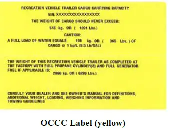
The upper portion of this yellow label is federally required and includes the maximum Occu-pant and Cargo Carrying Capacity that may be placed in or on the trailer as it was manufactured and weighed before leaving the factory. This maximum capacity would not include the weight of a full fresh water tank. The full load of water weight would need to be subtracted from the maximum cargo weight. Additions or other changes made to the trailer after it leaves the factory will affect (reduce) the OCCC. The lower portion of this label is provided voluntarily and indicates the weight value of the trailer as it was manufactured and weighed at the factory. It includes full propane tanks and full generator fuel (if so equipped).
NOTE:
The total weight capacity of the tires on your RV can be less than the GVWR. The calculation for the actual weight on the RV tires does not include the tongue weight. Your tow vehicle, not the RV tires, is actually carrying the tongue weight.
For example, if the tires are rated at 2,000 lbs. each x 4 tires = 8,000 lbs. and the RV has a GVWR of 9,000 lbs. with a tongue weight of 1,200 lbs. The actual weight on the RV tires is (9,000 – 1,200) which equals 7,800 lbs. which is within the weight rating of the tires.
The Federal Certification Label is required by the government to verify the trailer com-plies with all motor vehicle standards for Canada and the United States. It includes the following information: Manufacturer name, VIN, GVWR, GAWR (front/rear), tire and rim sizes and cold tire inflation pressures.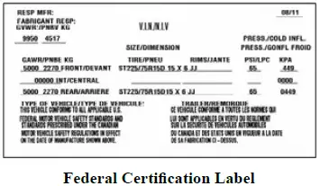 Tire and Loading Label provides information on the tire sizes, cold tire inflation pressures, the VIN and maximum cargo capacity. The maximum cargo capacity listed on the label does not include the weight of a full load of water. If you have further questions, please contact your dealer or our Customer Service department.
Loading Your Recreation Vehicle
Warning
- Never load the RV in excess of the GAWR for either axle. Overloading your RV may result in adverse handling characteristics and dam-age to the RV.
- DO NOT EXCEED YOUR GVWR! This means you should weigh your RV as loaded for your normal travel to determine the actual weight. If you exceed the GVWR, you MUST remove items from the RV, or drain liquids, then re-weigh the vehicle to ensure you have achieved a safe weight. Do not travel with full grey/black holding tanks. This not only wastes gas but, depending upon the location of the grey or black holding tanks, can affect handling characteristics Store and secure all loose items inside the RV before traveling. Overlooked items can become dangerous projectiles during a sudden stop.
Distribute cargo side-to-side so the weight on each tire does not exceed one-half of the GAWR for the either axle. Make sure any tie-down straps (if so equipped) on appliances or furniture are secure. Load heavy objects on the floor, or as low as possible.
Warning
- Your recreation vehicle’s load capacity is designated by weight, not by volume, so you cannot necessarily use all available space when loading the vehicle. Do not exceed your GVWR and ensure you are loading the vehicle as evenly as you can for the best possible handling. Ensure heavy items are secured so they do not shift during travel.
- Store items in areas designated for storage. Do not store anything in the areas reserved for the converter, electrical panels or furnace or water heater, etc.
- Read all Instructions for Weight Terms User Manual
-
Jayco Eagle Fifth Wheels 2023 Cargo Carrying Accessory Receiver User Manual
- https://autouserguide.com/jayco/fifth-wheels/jayco-eagle-fifth-wheels-2023-cargo-carrying-accessory-receiver-user-manual/
-
Cargo Carrying Accessory Receiver
Warning
Receiver is for cargo-carrying accessories ONLY. DO NOT tow any trailer or other vehicle. The load Limit for this receiver is 300 lbs. maximum. Use for towing or exceeding the load limit will void the warranty. Failure to follow the instructions can cause the carrier to collapse or items to fall which could cause an accident resulting in death or serious injury.Rear Bumper
Caution
Do not add items to the recreation vehicle’s rear bumper. Add-on items will eventually damage your bumper. Damage caused by such aftermarket equipment installation or improper loading voids the Towable Limited Warranty.The rear bumper of your RV is not designed to carry cargo. Items that extend beyond the bumper OR weigh over 100 lbs. (45kg) will place undue strain on the bumper. The 100 lb. bumper capacity includes the weight of the spare tire (if so equipped).
NOTE:
Some items may fall within the given weight range, (IE: bike racks) however, they can still cause damage. In addition, extra weight behind the axle may reduce the hitch weight which can adversely affect handling.Fifth Wheel Pin Box (customer supplied).
Hitch selection affects the towing and handling characteristics of your recreation vehicle. There are many kinds of hitches available and assuring that you have the correct hitch in-stalled is critical to a safe towing.
Ask your dealer about the proper class and type of hitch you need to purchase for your individual tow vehicle/RV combination. A fifth wheel requires a pin box hitch bolted directly to the floor of the truck box through the frame.
The hitch class rating based on the capacity that hitch has for towing and a weight classification. The weight classification is determined from the hitch’s weight carrying capacity (the pin box weight on a fifth wheel). Before selecting a hitch, you must know your GVWR and pin box rating. The rating of the hitch package purchased should be equal to or greater than the RV’s GVWR and the pin box rating.Caution
Using an oversized or undersized hitch can cause damage to the RV frame. We (as your RV manufacturer) cannot be responsible for the tow vehicle suspension system. The final ball height after the tow vehicle/fifth wheel combination is completely hooked up is a factor that must be considered. To avoid over-loading your trailer axles and minimize possible handling difficulties, your trailer should be level when hooked to your tow vehicle. Do not overload your tow vehicle.Equipment that sometimes gives autos, trucks and sport utility vehicles a softer ride can accentuate swaying when pulling a RV; conversely, suspension that is too stiff will increase vibration, bounce and accelerate wear of your tow vehicle and RV combination. Your recreation vehicle manufacturer cannot be responsible for the suspension system of any tow vehicle. There are a variety of tow vehicle suspension systems available that will affect the pin box height, stability, and levelness of a hooked-up RV. Make sure your dealer is aware of the tow vehicle you are using so a compatible hookup is achieved.
Fifth Wheel Pin Box
The fifth wheel factory-installed pin box is not interchangeable. Maintain the proper pin box weight on the hitch.
Fifth Wheel Pin Box Height
There is no recommended hitch height for fifth wheels; usually, the fifth wheel pin box is adjustable for variance in trucks and truck suspension systems. Adjust the hitch assembly so the tow vehicle and the fifth wheel are essentially levels. A high hitch will transfer weight behind the axles and cause the vehicle to fishtail. A low hitch will transfer additional weight to the hitch. Refer to the hitch manufacturer’s instructions to adjust the weight-distributing hitch to the proper height. If you have additional questions, consult with your dealer. Make certain your Dealer is aware of the tow vehicle you are using so a compatible hookup is achieved.
Fifth Wheel Hitching Procedure
The following procedure will help to assist you in securely hooking up your recreation vehicle to your tow vehicle.- Make sure the trailer wheels are blocked.
- Make sure the hitch lever is in its open or “cocked” position unless it has been designed to open automatically. Adjust the fifth-wheel travel trailer pin to the proper height. Lower the tailgate, if applicable.
- Back the truck so the hitch encircles the fifth-wheel/travel trailer pin.
- A gentle contact of the hitch saddle against the pin will cause the mechanism to close.
- Secure the hitch lever as specified by the manufacturer.
- Put the truck in drive (DO NOT press on the accelerator) and ‘bump’ the hitch to make sure it is locked.
- Be sure to raise the fifth-wheel landing gear all the way up.
- Attach the breakaway switch cable to the tow vehicle.
- Plug the wire harness/connector plug from the tow vehicle to the fifth wheel.
- Remove the wheel chocks from the trailer wheels.
Fifth-wheel landing gear can be operated manually. The fifth wheel landing gear must be fully retracted before moving or towing the RV to prevent damage.
Warning
DO NOT USE THE FIFTH-WHEEL LANDING GEAR TO SUPPORT THE TOW VEHICLE WEIGHT. The fifth-wheel landing gear is designed to bear the front-loaded weight of the RV only. -
Read all Instructions for Cargo Carrying Accessory Receiver User Manual
-
Jayco Eagle Fifth Wheels 2023 Wire Harness/Connector Plug User Manual
- https://autouserguide.com/jayco/fifth-wheels/jayco-eagle-fifth-wheels-2023-wire-harness-connector-plug-user-manual/
-
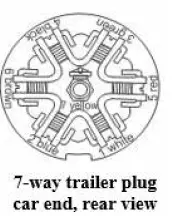
Wire Harness/Connector Plug
A 7-way wire harness/connector plug is wired into your trailer to connect electrical power from the tow vehicle for travel. This supplies power to the RV brakes, taillights, clearance lights, turn signals, brake lights, etc. Wiring to operate your brakes must be the same size in both the tow vehicle and RV (the RV brake wiring is a 12-gauge wire). When attaching wires to your tow vehicle, tape all the connections for moisture protection.
The connector plug may build up corrosion with extended use. It should be cleaned periodically to insure good electrical contact. Make sure the connector plug is kept clean and protected from road elements as you travel.NOTE:
A 12V circuit tester is recommended to verify the trailer connections.
Weighing Your Tow Vehicle and RV
When the RV is fully loaded it should be weighed. The actual weight of the vehicle, all options, liquids, the hitch weight, and your personal cargo is important for you to know so you do not exceed the GVWR. Two important factors when loading your RV are total weight and balance. It is imperative that you verify compliance within all applicable weight ratings. Overloading your RV will void the Towable Limited Warranty and the warranties of many component part manufacturers. Periodically weigh your RV at a public scale to determine proper load distribution. To obtain the side-to-side weights, there needs to be enough space on either side of the scale to accommodate the RV being partially off the scale. Keep in mind that individual scales will operate differently.
To weigh your tow vehicle and RV
Warning
- The total weight of your tow vehicle and RV must not exceed the GCWR. Do not assume that you can tow an RV that happens to be within the capacity of the tow vehicle hitch. By doing so, you may exceed the total GCWR of your tow vehicle and RV towing combination.
- It is important to redistribute the load to avoid component failure as well as to improve the handling characteristics of the vehicle and not void the Towable Limited Warranty.
Your RV must be weighed fully loaded (with food, clothing, fuel, water, propane, supplies, etc.).
- Weigh the RV including the tongue weight, while detached from the tow vehicle. This actual overall weight must be less than or equal to the GVWR for safe operation. If the overall weight is greater than the GVWR, some contents must be removed until the actual overall weight is less than or equal to GVWR.
- Hitch the RV to your tow vehicle. Weigh the RV and the tow vehicle to determine the GCW. Make sure that this rating is less than or equal to the GCWR as specified by the manufacturer of your tow vehicle. If this overall weight is greater than the GCWR, some contents must be removed to bring the combination into compliance with the listed ratings.
- Weigh the RV while attached to but excluding the tow vehicle. This will result in the actual weight that is exerted on all of the RV tires. This weight may be subtracted from the overall RV GVWR to determine the actual “tongue” weight.
- With the RV still attached to the tow vehicle, weigh each wheel position separately to ensure each tire is not overloaded.
To determine the wheel position weight - Pull the RV onto the scale so only one tire is on the scale. Record the weight. Your RV must remain as level as possible on the scale (even though an axle or side is not physically on the scale).
- To calculate the opposite side of the RV wheel position weight, subtract the first side’s weight from the weight determined in step #3.
If there is a difference in the weights on one side of the vehicle as compared to weights on the other side, components (tires, wheels, brakes, springs, etc.) on the heavier side could be overloaded, even though the total axle load is within the GAWR. Once actual weights are obtained, compare them to the Weight Information Label weight ratings to ensure you are below the posted minimum ratings. See the Weight Terms and Loading Your RV sections for important weight information.
-
Read all Instructions for Wire Harness/Connector Plug User Manual
-
Jayco Eagle Fifth Wheels 2023 Towing User Manual
- https://autouserguide.com/jayco/fifth-wheels/jayco-eagle-fifth-wheels-2023-towing-user-manual/
-
Towing
If your RV is equipped with the Command Control Bluetooth system, make sure you turn off your battery disconnect switch according to the following instructions.
Caution
- BEFORE TOWING YOUR RV ON THE ROADWAY: TURN OFF THE BATTERY DISCONNECT SWITCH!
- Certain components inside the RV can unexpectedly activate which could result in personal injury or property damage.
This caution label has been placed in an area near the battery disconnect switch on your RV.
NOTE:
On some models, the battery disconnect switch may be located in the compartment with the propane tanks.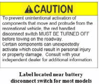
Warning
- Your RV braking system is rated for operation at GVWR, not GCWR.
- Whenever possible, do not travel with waste in the holding tanks. Liquid or debris in the holding tank(s) may affect the towing characteristics and may result in property damage or personal injury.
- The propane cylinder(s) should be turned off when traveling. Most refrigerators will keep food cold or frozen for eight hours without running while you travel.
Your RV will travel safely and comfortably at highway speed limits. It will take longer than a passenger automobile to reach that speed. Allow more time to go around vehicles you are passing. Avoid situations that might require sudden momentum changes as the length of the tow vehicle/RV combination affects your ability to quickly cut back into traffic. Swerves and sharp turns, especially at high speeds, could result in loss of control of the tow vehicle/RV. Slow down in advance of dips, bumps, and railroad tracks to reduce the jolting to your tow vehicle/RV combination. Proceed slowly and let the trailer tires pass over them before accelerating. Adverse weather conditions and extremes in terrain may affect the performance and handling of your tow vehicle. Do not operate the tow vehicle cruise control on icy or extremely wet roads, winding roads, heavy traffic, or in any other traffic situation where a constant speed cannot be maintained.
When descending a long hill, drop down into a lower gear or range. Avoid conditions that require excessive and prolonged use of your brakes. Apply and release brakes at short intervals to allow them to cool. The tow vehicle transmission and engine will help in controlling downhill speed and can lengthen brake life. Use care when accelerating or decelerating on a slippery surface. Abrupt speed changes can cause skidding and loss of control.
Know the weight and size of your towing combination and observe any posted weight and clearance limits. The added height of roof air conditioners, TV antennas, or floodlights may cause clearance problems around some tunnels, canopies, and hanging signs. When turning, the tires do not follow the path of your tow vehicle tires. The RV will make a tighter turn than the tow vehicle. Compensate for this action by carefully pulling the tow vehicle out into the intersection further than you would normally so that the RV clears the curb. When making a turn, check the road clearance and be aware of others. Swerves and sharp turns, especially at high speeds, could result in loss of control of the RV. If your camping destination does not have pull-through sites, pick a level site and back in carefully. Check to ensure there are no obstacles in your path and that you have plenty of vehicle clearance.
After the RV is in the desired location, set the tow vehicle parking brake. Block all RV wheels securely with wheel chocks to prevent it from rolling.RV Brake System
Even though your RV is equipped with brakes designed for GVWR, proceed with caution until you become accustomed to your RV’s stopping distance. Driving through water deep enough to wet the brakes may affect the stopping distance or cause the vehicle to pull to one side. Check the RV’s brake operation in a safe area to be sure they have not been affected. Never operate any vehicle if a difference in braking efficiency is noticeable.
Electric Brakes
Warning
Failure to maintain the brakes in proper working condition as specified in the operator’s manual supplied by the axle OEM will cause property damage, personal injury and possibly death. Consult with your dealer for assistance.The electric brakes are designed to work with the tow vehicle brakes. To maintain proper braking performance, both the RV and tow vehicle brakes must be used together. Separate use of the braking systems will cause accelerated wear and damage. When your RV is new, it is impossible to adjust the brake shoes precisely. It takes approximately 1,000 miles and/or 50 medium to heavy stops to “burnish” fit or “seat” the shoes to the brake drum. After the initial break-in period, your brake shoes must be adjusted accurately for the best performance and increased durability.
Braking system components include:
- Tow vehicle battery
- Tow vehicle brake controller
- Wire harness/connector plug
- Trailer battery
- Breakaway switch and alarms
The tow vehicle battery is the primary source of power for your RV’s electric brake operation. To ensure available power when needed, keep your tow vehicle battery and charging system working properly.
Brake Controller (customer supplied)
The brake controller should be installed in the tow vehicle to work in conjunction with the RV electric brakes. Consult with your dealer or the brake controller OEM to decide what is right for your towing combination.
-
Jayco Eagle Fifth Wheels 2023 Breakaway Switch User Manual
- https://autouserguide.com/jayco/fifth-wheels/jayco-eagle-fifth-wheels-2023-breakaway-switch-user-manual/
-
Breakaway Switch
Caution
NEVER use the breakaway switch and trailer brake system as a parking brake. Doing so would create a high amp draw on the battery and converter. This can cause damage to wiring, connectors and the breakaway switch.Your RV may be equipped with a breakaway switch. The breakaway switch is a crucial part of the RV braking system. Located on the travel trailer A-frame, or beside the fifth wheel pinbox, this switch will apply the RV brakes if the trailer becomes detached from the tow vehicle. Attach the breakaway switch lanyard to a permanent part of the tow vehicle when hitching your RV. On a travel trailer, do not attach it to the hitch ball or similar removable parts. If the RV becomes detached from the tow vehicle, the pull pin will be pulled from the switch. This automatically causes the switch to “close” and activates the RV brakes.
Hydraulic Brakes (if so equipped)
Your RV may be equipped with hydraulic surge brakes that operate automatically as the tow vehicle’s brakes are applied. When speed is decreased and brakes are applied, the weight of the trailer moving forward creates a reaction, which causes the brake fluid inside the wheel cylinder to activate the brake shoes against the drum. As a result of this design, backing the RV uphill may activate the surge brake system making it difficult to continue in reverse. To aid in backing up the RV:
- Prior to backing up a slope or through soft ground, pull the recreation vehicle forward slightly to assure that the actuator socket is in the forward position.
- Move the lever on the side of the actuator downward from the “towing position” along the curved slot in the actuator frame to the “backup position.” The slot has a notch at the bottom of its travel. Push the lever down to engage the locking notch.
- The RV will now back up. This lever will slide into the correct position when pulling forward.
It is extremely important to keep the master cylinder full at all times. An empty cylinder invites moisture.
Disc Brakes (if so equipped)
If your RV is equipped with disc brakes, see the manufacturer’s owner’s manual for detailed safety and maintenance information.
Towing Behind Your RV
Warning
If you do not have a Jayco factory-installed hitch receiver, towing items behind your Jayco RV, or overloading the rear, will void the warranty and may result in: damage to the RV or add-on items, towing difficulties, property damage and/or personal injury.NOTE:
IF YOU DO NOT HAVE A JAYCO FACTORY-INSTALLED HITCH RECEIVER, DO NOT TOW ANYTHING BEHIND YOUR RV. THE RV FRAME AND BUMPER ARE NOT DESIGNED FOR TOWING.NOTE:
A hitch equipped for trailer towing will have tabs to hang the safety chains and there will be a bracket for the trailer wiring plug. There should also be a label on the hitch stating the maximum towing capacity.Factory Installed Hitch Receiver (if so equipped)
Warning
- If you do not have a Jayco factory-installed hitch receiver, towing items behind your Jayco RV, overloading the rear, or failure to adhere to the specified weight capacities will void the warranty and may result in: damage to the RV or add-on items, towing difficulties, property damage and/or personal injury.
- The hitch receiver installed on your RV is a weight-carrying hitch only. Do not use weight distribution bars or equipment when towing. Using weight distribution bars or equipment with the hitch receiver will void the warranty and may cause damage that could lead to adverse trailer combination towing and handling, loss of control or an accident resulting.
NOTE:
IF YOU DO NOT HAVE A JAYCO FACTORY-INSTALLED HITCH RECEIVER, DO NOT TOW ANYTHING BEHIND YOUR RV. THE RV FRAME AND BUMPER ARE NOT DESIGNED FOR TOWING.Additional Towing – Multiple Trailer Combinations (if so equipped)
If your RV (applies to limited fifth wheel models only) is equipped with a factory-installed hitch receiver, you have the ability to tow an additional boat or another watercraft trailer behind your RV.
The hitch receiver may be used as a weight-carrying hitch to tow a boat or other watercraft trailer. Do not use a bar longer than 10 inches (254 mm). The maximum length of the drawbar is from the center of the fastening pin to the center of the ball. The maximum trailer tow rating of the fifth wheel hitch is 3,000 lbs. (1361 kg.) with a maximum tongue weight of 300 lbs. (136 kg.). The receiver may be also used for attaching a cargo basket/carrier for other items. Ensure the cargo carrier is properly attached to the hitch receiver and all cargo is properly secured in place. The cargo weight carrying capacity includes the weight of the cargo carrier. The maximum total weight when used to carry cargo is 300 lbs. (136 kg.)..
The trailer being towed by your RV must be properly equipped with brakes. Contact your tow vehicle dealer or manufacturer for assistance in determining whether a separate braking system is recommended and what the limits are for towing multiple trailer combinations. Check the state or province where your tow vehicle and RV are registered as well as any state or province where travel is planned in the U.S. and/or Canada for brake requirements and regulations.
These labels have been placed on the hitch receiver and on the rear bumper of your RV. Be sure to read, understand and follow the information on them.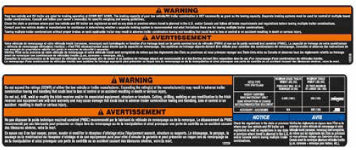
- Read all Instructions for Breakaway Switch User Manual
-
Jayco Eagle Fifth Wheels 2023 Second Trailer Hitching Procedure User Manual
- https://autouserguide.com/jayco/fifth-wheels/jayco-eagle-fifth-wheels-2023-second-trailer-hitching-procedure-user-manual/
-
Second Trailer Hitching Procedure
The following procedure will help to assist you in securely hooking up the second trailer to your RV.
- Make sure the second trailer wheels are blocked.
- Turn the tongue jack crank to raise the trailer tongue above the hitch ball.
- Open the coupler latch on the trailer hitch.
- Back the tow vehicle/ fifth wheel combination into the proper position.
- Turn the second trailer tongue jack crank to lower the coupler onto the hitch ball.
- Close the coupler latch after it is completely seated.
- Remove the dolly wheel or platform (if so equipped) and retract the tongue jack to its maximum height.
- Attach the breakaway cable to the hitch receiver on the RV fifth wheel.
- Attach the safety chains. See Safety Chains for additional information.
- Plug in the wire harness/connector.
- Walk around the RV and the second trailer making sure all exterior lights are working correctly.
- Remove the trailer wheel blocks.
Wire Harness/Connector Plug
A 4-way wire harness/connector plug is wired into your RV to connect electrical power from the RV to the second trailer for travel. This supplies power to the taillights, clearance lights, turn signals, brake lights, etc. The 4-way wire harness/connector is not wired for operating electric brakes. The connector plug may build up corrosion with extended use and should be cleaned peri-odically to insure good electrical contact. Make sure the connector plug is kept clean and protected from road elements as you travel.
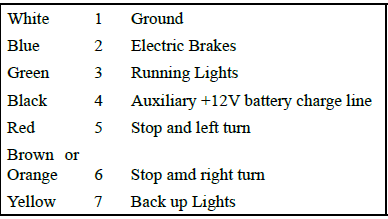

Entrance Door Step(s)
Make sure your entrance step is fully extended before exiting the vehicle and retracted prior to towing.
Lubricating the step mechanism
Carefully clean the area around the pivot points (the rivets involved in the motion of the mechanism). Lubricate these pivot points with an automotive-grade, non-staining lubricant every 30 to 60 days.
Wipe any excess lubricant off of the step and then clean the entire step after lubricating.Step Light
Your RV may be equipped with a switch located on the skirt (in front of the steps) which operates a light located under the step assembly.
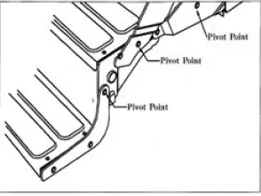
Stowable Entrance Door Step (if so equipped)
Warning
- Maximum Weight Capacity 500 lbs.
- Maintain hold of the steps until lowered all the way to the ground.
- Prior to use, legs must be adjusted properly to ensure the step is level.
- Ensure that both latches are engaged when the steps are stored.
- Do not try to lift the steps while the door is closed. This may cause damage to the steps and the door.
- Make sure people and pets are clear of the area when rotating the steps down to the ground or raising them for storage.
Failure to follow these guidelines could result in property damage or serious injury.
Your RV may be equipped with one (or two) sets of the Stowable Entrance Steps. With these steps, there is no accessible steps mounted on the exterior of the RV. They are a one piece solid (3 or 4 step) assembly that latches inside the doorway of the RV. The steps rotate down and out of the doorway and include two adjustable feet to provide stability while parked on rough terrain.
-
Read all Instructions for Second Trailer Hitching Procedure User Manual
-
Jayco Eagle Fifth Wheels 2023 Entrance Door User Manual
- https://autouserguide.com/jayco/fifth-wheels/jayco-eagle-fifth-wheels-2023-entrance-door-user-manual/
-
Entrance Door
Always hold onto the entrance door when opening or closing it. Damage caused because you failed to do so is not covered by the Limited Warranty.
Caution
Make sure the entrance door is completely closed and locked when traveling. Locking the door helps prevent it from opening unintentionally and keeps intruders from your recreation vehicle.The entrance screen door may be equipped with a slide panel that allows access to the entrance door handle and locks. The entrance door may also be equipped with both a regular door lock and a dead bolt lock.
Keys
Several keys are provided when you purchase your vehicle. Most keys have an individual key number stamped on the plate. Record these key numbers and keep the information in a safe place. You can order a key blank from your dealer to have duplicate keys made. If you lose the keys, contact your dealer or a locksmith for assistance.NOTE:
Locks on entrance and baggage doors need biannual lubrication using a light coat of silicone spray. Conditions such as rain, salt, dust and pollution may increase the maintenance needs.Rear Backup Camera Prep
Your recreation vehicle may be pre-wired for installation of a (customer-supplied and customer installed) rear backup camera and camera ON/OFF switch that can be used as an observation/security camera.
Some models are equipped with a camera accessory power wire that is pre-routed at the factory to the bedroom, or to the command center panel inside the entrance door. An ON/OFF switch can be installed (using the accessory power wire) either in the bedroom or the command center panel. The camera monitor is then plugged into the camera charge center in the bedroom or the command center panel to be used for observation or security purposes.
Some models may have a pre-installed power switch for the camera located in an exterior compartment (e.g. battery storage or utility center bay). Your dealer can tell you if your model comes with a switch pre-installed.
An instruction sheet is included in your warranty packet that details camera and switch installation, along with information to help you locate the power wire.Warning
- Camera/monitor system aids in the use of, but does not replace vehicle side/rear-view mirrors.
- Objects in camera/monitor view are closer than they appear. When backing up, proceed cautiously and be prepared to stop.
Campsite Hook-Up
- Refer to Electrical Systems section before connecting the shore line power cord (when using full hook-up) OR before starting the generator (if so equipped) or operating the vehicle on 12-volt power when dry camping.
- Refer to Fuel and Propane System section before using the LP system. Open the LP gas tank valve (if so equipped) slowly. There may be air in the lines and five to thirty seconds of time is needed to bleed air before LP vapor fills the lines.
- Refer to Plumbing Systems section before connecting the fresh water supply or turning ON the water pump or water heater.
- When using full hook-up, connect the sewer hose to the campsite sewer hook-up.
- If applicable, start the refrigerator and the cooling or heating system.
NOTE:
For extended dry camping, management of all your resources is essential. Check your battery levels and conserve battery power, use it sparingly.3.0 Leveling System (if so equipped)
The 3.0 Leveling System is an electric 4 or 6-point automatic leveling control. The system utilizes one main control board and a separate waterproof remote level sensor to measure and manage level point.
It can be operated from several user interface devices including:
- Auto Leveling Control Touch Pad – Mounted outside the RV within view of the hitch.
- MyRV® OneControl Touch Panel (OCTP) – Mounted on a wall inside the living space of the RV.
- MyRV® OneControl Leveling App – App available from Google Play or iTunes for Apple or Android devices.
- Linc® Remote Control – Located inside the entrance door (optional).
The following is an overview of each application. Refer to the Ground Control 3.0 manual included in your warranty packet for complete safety and operating instructions.
Warning
- Never use the auto leveling system to lift the RV off the ground. Lifting the RV so the wheels are not touching the ground will create an unstable and unsafe condition.
- The leveling system is designed only for leveling the unit and should never be used to provide service for any reason under the RV, such as changing tires or servicing the system. It is not recommended that you change a tire yourself.
- Park the RV on level, solid ground.
- Ensure all jack locations are clear of debris, obstructions or depressions.
- People and pets should be clear of the RV while the system is in operation.
- The battery should be fully charged or the RV plugged into shore power prior to operating the leveling system.
- Keep hands and body parts clear of fluid leaks. Hydraulic fluid leaks may be under high pressure and can cause serious skin-penetrating injuries.
- Using this leveling system in a manner other than its intended use will void the limited warranty.
Failure to act in accordance with these warnings may result in serious personal injury or death!
-
Jayco Eagle Fifth Wheels 2023 Auto Leveling Control Touch Pad User Manual
- https://autouserguide.com/jayco/fifth-wheels/jayco-eagle-fifth-wheels-2023-auto-leveling-control-touch-pad-user-manual/
-
Auto Leveling Control Touch Pad
- Red/Green LED indicates system status
- Up Arrow extends front jacks (landing gear)
- Down Arrow retracts front jacks (landing gear)
- Auto Level button places the system in the auto level mode
- The hitch Height button initiates the Hitch Recognition feature
- Retract All button puts leveling system in full retract mode
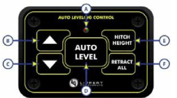
NOTE:
Pressing both arrow buttons simultaneously turns on the touchpad. Touchpad will time out after 7 minutes of non-use.Auto Level Touchpad LED Indicator status
- OFF – Touch pad is locked
- Solid Green – Touch pad is active
- Blinking Green – Jacks are moving
- Solid Red – Low battery
- Blinking Red – Error
The One Control touch screen or Leveling App will show the specific error. Refer to the troubleshooting section of the manufacturer’s manual to clear the error. Auto
Leveling Touch Pad
Unhitching the RV
- Before unhitching from the tow vehicle, ensure the RV is parked on a level surface and tires are choked.
- Extend the inner legs of both landing gear (front jacks) to within 4”- 5” of the ground by pulling on the quick-release pins.
- Turn on the touchpad by pressing both arrow buttons simultaneously. LED illuminates solid green.
- Press the UP arrow button to extend the front jacks to lift the front of the RV taking weight off the hitch.
- Uncouple the RV connection to the tow vehicle. Pull tow vehicle away.
Auto Leveling
When the leveling cycle has started, it is important there is no movement inside the RV until leveling is complete. Failure to remain still during leveling could affect the performance of the leveling system.
- Turn on the touchpad.
- LED will light up solid green.
- Select AUTO LEVEL and the auto-leveling process begins. The front of the RV will seek a position near level. Rear jacks will be grounded (on 4-point system). Side to side leveling will begin.
- Each jack will perform a final grounding touch.
On a 6-point system, the (2) middle jacks will be grounded to stabilize the trailer. The (2) middle jacks do not level the RV.
If the AUTO LEVEL sequence does not perform as described above, place the system in manual mode and test that the jacks operate correctly by using the One Control touch panel inside the RV.
One Control Touch Panel
- Press the button at the bottom of the touch panel to power up the display.
- Select MyRV® Control Panel from the menu listing.
- Select the Leveler icon.
The following functions can be operated using the One Control Touch Panel inside the RV. Standard Mode and Menu
- Basic Jack operation
- Unhitching instructions
- Auto Leveling
- Hitch Recognition
OneControl App (for phone or tablet)
- Download the OneControl App for your device from Google Play Store or iTunes.
- To access the OneControl App, ensure there is the power to the RV’s wireless network hub.
- Navigate to the device’s Wi-Fi settings. Turn the wireless feature on and connect to the MyRV® wireless network.
- A password will be required to access the network. The password is found on the RV’s wireless hub (8 capital alpha characters).
- Open the OneControl App on your phone or tablet.
- The App will request the user to “Agree” with a license agreement, and connect to the MyRV® system by entering the PIN (default is 1,2,3,4 for OneControl Touch Panel). It will prompt you to create a new PIN and then re-enter the new PIN.
NOTE: The PIN is not needed or asked for if the tablet is attached to the docking station and connected to the USB cable inside the RV. - The App will now display all functions. Choose Leveler.
The following functions can be operated using the One Control App. Basic Jack operation
- Read all Instructions for Auto Leveling Control Touch Pad User Manual
-
Jayco Eagle Fifth Wheels 2023 Linc Remote Control User Manual
- https://autouserguide.com/jayco/fifth-wheels/jayco-eagle-fifth-wheels-2023-linc-remote-control-user-manual/
-
Linc Remote Control
Configuring the remote to sync with the OneControl Touch panel:
- Press the chrome button on the bottom of the remote to turn it on. Enter the PIN (default is 0,0,0,0). The PIN can be changed after entering the default PIN. A menu will appear, choose Leveler from that menu.
- Turn the OneControl Touch Panel ON inside the RV.
- At the top of the Touch Panel screen press the “CONNECTED” icon quickly (6) times.
- A GEAR icon will appear at the top of the screen that says “OPTIONS”. Press the GEAR icon.
- Screen display changes to “Select Operation” with arrows on the left side of the screen. Use to arrows on left side of screen. Scroll to “WIRELESS CONFIG”.
- Press the ENTER button at the bottom of the screen.
- The screen will display “Wireless Configuration Press any Linc button to sync”.
- Press any button on the remote control while in Leveler mode and the remote will be connected.
Pressing the ABORT button on the touch screen will cancel the configuration sequence.
The following functions can be operated using the Linc Remote Control. Refer to the manufacturer’s manual for complete instructions.- Basic Jack operation
- Unhitching Instructions
- Auto Leveling
Troubleshooting
Refer to the manufacturer’s manual for troubleshooting information which includes the following:
- OneControl Touch Panel Error Codes
- Special Jack Error Codes on the OneControl Touch Panel
- How to manually override the jack motor
- Setting Zero Point Calibration
- Zero point is the programmed point that the RV will return to each time the Auto Level feature is used. Zero Point is only available on the OneControl Touch Panel.
- Preventative Maintenance tips
Stabilizer Jacks
Warning
- DO NOT USE THE STABILIZER JACKS TO LEVEL THE RV. It is important to remember that the stabilizer jacks are to be used only for support while occupying and moving around the RV. They are not designed to support the weight of the RV.
- The stabilizer jacks must be fully retracted before moving or towing the RV to prevent stabilizer jack damage.
Each stabilizer jack can be individually adjusted to stabilize the RV for use. When setting up on the soft ground, you may wish to place a wood pad or the equivalent under each stabilizer jack foot to help keep the jack from sinking into the ground.
Manual Stabilizer Jacks (if so equipped)
- To lower each jack, insert the jack crank onto the applicable stabilizer jackshaft.
- Turn the crank clockwise to lower each leg until it contacts the ground and stabilizes the RV.
To raise each jack, insert the jack crank onto the applicable stabilizer jack shaft and turn the crank counter-clockwise.
Electric Stabilizer Jacks (if so equipped)
Control switches for the stabilizer jacks are typically located on the (door) side of the unit above the stabilizer jack(s). To lower each jack, press the control switch until each leg contacts the ground and stabilizes the unit. To raise the jack, press the control switch until the jack is returned to the retracted position.
Manual Override
The electric stabilizer jacks may have a built-in manual override system. The override coupler is located on the end of the stabilizer jack opposite the electric motor. One of the wire motor leads must be disconnected to prevent backloading the motor and causing more damage. Disconnect the battery from the system prior to manual operation. Insert the 1/2” diameter crank handle inside the coupler. The slot in the end of the crank handle accommodates the pin inside the coupler to allow manual extension/retraction of the stabilizer jack. Rotate the handle clockwise to retract and counter clockwise to extend the jack.
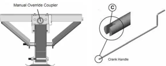
NOTE:
The gears can be stripped out if the stab jack is manually retracted/ extended to its fullest extent and the operator continues to rotate the manual override.The following functions can be operated using the Linc Remote Control. Refer to the manufacturer’s manual for complete instructions. One of the wire motor leads must be disconnected to prevent backloading the motor and causing more damage. Disconnect the battery from the system prior to manual operation. Insert the 1/2” diameter crank handle inside the coupler. The slot in the end of the crank handle accommodates the pin inside the coupler to allow manual extension/retraction of the stabilizer jack. Rotate the handle clockwise to retract and counterclockwise to extend the jack.
-
Jayco Eagle Fifth Wheels 2023 Emergency Towing User Manual
- https://autouserguide.com/jayco/fifth-wheels/jayco-eagle-fifth-wheels-2023-emergency-towing-user-manual/
-
Emergency Towing
Warning
Never allow anyone to go under the recreation vehicle while it is being lifted and/or being towed.If your recreational vehicle needs to be towed, please contact an emergency road service provider or a qualified service facility for assistance.
Wheel Lugs
After your first trip, check the wheel lug torque periodically for safety.
Lugs should be checked:
- After winter storage
- After a wheel removal
- Before starting a trip
- Following extensive braking
Lug nuts should be tightened in two stages. Lugs should be started by hand, then torqued to intermediate values (Stage 1) on the chart then torqued according to the final torque values on the chart. Refer to the Wheel Lug Nut Diagram below.
- Use the correct star pattern sequence to attach the recreation vehicle wheels.
- Start all nuts by hand to prevent cross threading.
- Tighten the nuts in the sequence shown.
NOTE:
The proper method of tightening wheel lug nuts is with a properly calibrated torque wrench and socket, not with an impact wrench or by hand. Do not use a 4-way lug wrench or any other type of wrench that does not measure the actual pressure applied to the lug nut. Lug nuts should be tightened according to the proper lug pattern on your wheels. Refer to the Wheel Lug Nut Diagram below.Warning
- Check and tighten wheel lug nuts regularly to make sure they did not loosen during travel. Wheel lug nuts must be applied and maintained at the proper torque levels to prevent loose wheels, broken studs and possible separation of the wheel(s) from your recreation vehicle. The lug nuts on the wheels of your recreation vehicle must be maintained according to listed torque values (see Wheel Lug Nut Torque Chart.) Over-torqued and/or under-torqued wheels may result in component failure.
- Wheels should ALWAYS be mounted and properly torqued by a qualified service technician using the proper tools.
- Failure to maintain proper torque of the wheel lug nuts could lead to separation of the tire and wheel while driving, possibly resulting in property damage or personal injury.
Wheel Lug Nut Diagrams
Because of the importance of having proper torque on the wheel lug nuts, you should always have the wheels mounted and properly torqued by a qualified technician using the proper tools.
Criss cross “star” patterns, as shown, must be followed during tightening sequence.
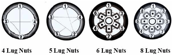
A Digital or Dial Torque Wrench is recommended.
Also applies to any service involving wheel or lug removal, during the life of the recreational vehicle.
Wheel Lug Nut Torque Values
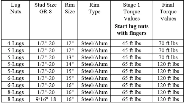
- Prior to travel and after excessive braking, wheel lug nuts should be checked for torque. Torque readings must fall within the Final Torque Values in chart above.
- Torque specifications should be checked using a proper torque wrench.
- If the torque falls below the Final Torque Values, additional torque is required.
- Check and re-torque lug nuts at 10 miles (16 Km), 25 miles (40 Km) and 50 miles (80 Km) and again periodically during travel. Refer to diagrams above for proper lug pat-tern and Final Torque Values. Thereafter check and maintain torque according to the Final Torque Values in the chart above.
Failure to follow these instructions may result in wheel loss, an accident, or loss of control, resulting in death or serious injury.
Lug Nut Pattern and Warning Label
The following labels showing the proper lug nut tightening pattern and a warning label are located on the driver side of the A frame hitch on travel trailers, and on the driver side of the pinbox on fifth wheel units. Lug pattern label will vary according to a number of wheel lugs.
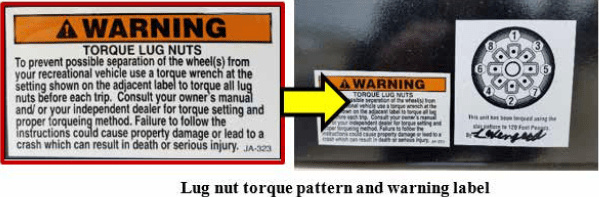
Because of the importance of having proper torque on the wheel lug nuts, you should always have the wheels mounted and properly torqued by a qualified technician using the proper tools. The proper method of tightening wheel lug nuts is with a properly calibrated torque wrench and socket, not with an impact wrench or by hand. Do not use a 4-way lug wrench or any other type of wrench that does not measure the actual pressure applied to the lug nut. Lug nuts should be tightened according to the proper lug pattern on your wheels. Refer to the Wheel Lug Nut Diagram below.
Jayco Eagle Fifth Wheels 2023 Torque Wrench Usage User Manual
Jayco Eagle Fifth Wheels 2023 Torque Wrench Usage User Manual
Torque Wrench Usage
- Tools should be maintained, in good condition, and stored appropriately.
- Avoid dropping or sliding a torque wrench. Dropping it can cause the instrument to lose reliable calibration.
- Damaged tools must not be used and must be removed from service for evaluation and either reported and re-calibrated or replaced.
- Do not use accessories or handle extensions unless specifically allowed by the torque wrench manufacturer.
- Do not use the torque wrench as the primary means of tightening or loosening fasteners.
- Torque wrenches are length specific.
- Grasp the torque wrench in the center of the handle when applying torque pressure.
- Place one hand on top of the other when using two hands.
- Apply torque in a slow, steady manner in a downward direction and avoid sudden “jerking” movements.
- When the wrench signals (by clicking, beeping or lights) that a specific torque has been reached, stop immediately.
Tires
Read and understand the following before taking your first trip in your RV.
Routine maintenance on your RV is important. To ensure your tires are operating safely, regular inspection of the tires and checking tire pressures is absolutely mandatory. Alignment, balance and bearing wear will affect tire wear. Make sure to look for cracking, bulging, uneven tread wear, etc.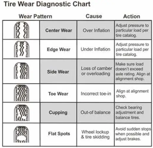
Caution
Tire wear should be checked frequently. Once a wear pattern becomes firmly established in a tire it is difficult to stop, even if the underlying cause is corrected.
Tire pressure
Danger
Failure to follow proper inflation guidelines may result in tire failure, which, under certain circumstances can cause loss of vehicle control or accidents that may result in property damage, bodily injury, and/or death.
You must follow the manufacturer’s inflation guidelines for maximum load capacity; underinflation is just as dangerous as overinflation.
Proper inflation should be monitored closely. Failure to do so could result in the overheating of a tire causing a blowout. Inflation pressure should be as recommended by the tire manufacturer or as the federal label for the recreation vehicle indicates. When you are using your Recreation Vehicle, check the inflation pressure weekly. Pressure should be checked when the tires are cold. During travel, tires heat up and pressure increases. Do not bleed air from hot tires or your tires may then be under-inflated.
NOTE:
Cold tire inflation pressure is defined as a tire that has not been used for three or more hours, or has been driven less than one mile. Tire inflation pressure of a hot tire may show an increase of as much as 6 psi over a cold tire.
Warning
- It is recommended that the tire pressure be checked at the beginning of each trip to obtain the maximum life of the tire. Follow the instructions listed on the Federal Certification label, to determine the correct tire pressure. Under-inflation may cause tire failures and swaying resulting in loss of control, injury, death, or property damage.
TOWABLE PRODUCTS ONLY
- Towable recreation vehicles are equipped with special trailer (ST) tires that have a maximum speed rating of 65 MPH (104 km/h). You should not exceed this speed rating. Exceeding the tire speed rating may result in tire failure, which could lead to an accident causing serious injury or death.
Changing A Tire
Warning
- Do not use the stabilizer jacks to support the recreational vehicle while under the vehicle or changing tires. The stabilizer jacks are designed as a stabilizing system only. Do not use the stabilizer jacks as a jack or in conjunction with a jack.
- Never raise the recreational vehicle by placing the jack under the axle, springs or any attachment parts.
Failure to comply with these guidelines could result in damage to the vehicle and risk causing serious injury or death.
When replacing tires:
- Be sure to use only tires that are rated for recreation vehicle use. The use of passenger tires should be avoided. The load rating/range embossed on the sidewall of passenger tires must be de-rated accordingly; they do not have the same load capability as tires that are specifically identified for recreational vehicle use. Failure to use tires that are properly matched to your recreational vehicle could lead to premature tire wear or less than optimum trailer handling.
- Be sure to replace it with a tire of the same size and specifications (refer to the Federal Certification label).
If you experience a flat tire on your recreational vehicle while driving, gradually decrease your speed and move the recreational vehicle to a safe place on the side of the road.
- Keep the recreational vehicle attached to the tow vehicle. Block the tire on the opposite side of the recreational vehicle from the tire you are changing.
- Loosen the wheel lug on the tire you are changing before jacking up the vehicle. DO NOT remove the lug nuts; only loosen them for ease of removal when the tire is off the ground.
- Locate the mainframe rail of the trailer (it spans from front to back just inside the tires).
- To raise the recreational vehicle, place the jack (hydraulic or screw) under the main frame rail. It must be just ahead of the front tire or just behind the rear tire.
Tire Replacement
Any service or warranty coverage on tires is to be handled by the tire manufacturer or the store representing the brand installed on your recreation vehicle. They are not to be returned to your dealer or recreation vehicle manufacturer. If you have questions regarding your tires, contact the tire manufacturer.
Read all Instructions for Torque Wrench Usage User Manual
Jayco Eagle Fifth Wheels 2023 Spare Tire Carrier User Manual
Jayco Eagle Fifth Wheels 2023 Spare Tire Carrier User Manual
Spare Tire Carrier
If your recreational vehicle is equipped with a spare tire, it will either be mounted under the unit (hoist) or on the rear bumper.
Hoist Mount
Warning
DO NOT exceed the maximum load capacities of 100 lbs. for the hoist. DO NOT use air driven guns or impact wrenches to lift the spare tire to the travel position.
Depending on your model, the spare tire may have (side or bottom) brackets or it will be mounted against the underside of the recreation vehicle (flush mount) to give it stability in travel.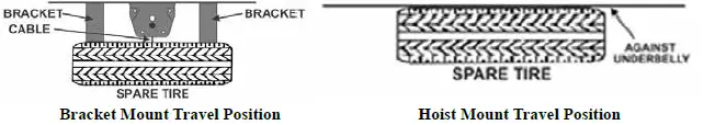
NOTE:
If your spare tire is a flush mount application, it must make contact with the underside of the recreational vehicle to insure maximum road clear-ance and stability in travel.
Raising and lowering the hoist
The crank handle to raise and lower the tire will be located (fastened to the sidewall) in a basement compartment of the recreational vehicle. Insert the crank handle into the crank access port located either in the center of the rear bumper, or on the sidewall of the RV. Turn the crank handle to raise/lower the tire. Two “crisp breaks” must be heard and felt to insure the proper seating of the tire for travel.
NOTE:
If the manual crank access port is located in a slideout, the slideout room must be in the travel position to allow the crank to reach the mechanism used to raise or lower the tire.
Securing the spare tire
To secure the spare tire in the travel position, put the steel hoist lift support located on the end of the cable through the rim of the tire. The hoist lift support clips need to seat inside the center hole of the tire rim. The valve stem of the tire MUST be pointed up (toward the bottom of the RV).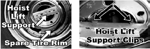
Bumper Mount
The spare tire bracket can be released and extended down to access a storage compartment at the rear of the trailer without removing the tire.
To extend the tire down
- Remove the cotter key from the pin holding the tire carrier in place.
- Remove the pin and extend the carrier away from the trailer.
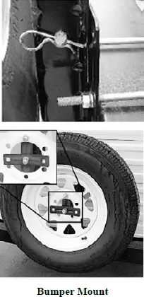
Always return the tire carrier to the upright position and lock it in place while traveling.
To remove the tire from the tire carrier
- Remove the lug nuts holding the tire in place.
- Remove the support bracket from the bottom lug.
- Pull the tire from the tire carrier.
To install the tire on the tire carrier
- Place the tire on the carrier with the top lug bolt inserted into one of the holes in the tire rim and the bottom lug bolt in the center of the rim.
- Install the top lug nut.
- Place the support bracket over the bottom lug bolt across the center of the rim (photo).
- Install the bottom lug nut over the support bracket.
- Tighten the lug nuts securely before returning to travel.
Vinyl Tire Cover (if so equipped)
Your tires are manufactured with components that cause “bleeding” onto the tire cover. To prevent this, it is recommended to use a separator (garbage bag, paper, cloth, etc.) between the tire and the cover.
Setting Up Your Recreation Vehicle
- Position the RV as desired.
- Level the RV (side-to-side). Leveling your recreation vehicle is important as the water drainage systems are designed with proper slope and must be level for proper operation, and the appliances perform best when level.
- Block the wheels securely to prevent the RV from moving.
Travel Trailer Set Up
- Unhook the wire harness/connector plug, safety chains and breakaway switch lanyard.
- Install the dolly wheel or platform.
- Release the weight distributing bars (customer supplied).
- Open the tongue jack coupler latch.
- Turn the tongue jack crank to raise the coupler above the hitch ball.
- Level the RV (front-to-back) with the tongue jack crank.
- Lower stabilizer jacks (If applicable).
- Pull the tow vehicle away.
Fifth Wheel Set Up
- Drop the landing gear (important!) See the operator’s manual for proper operation.
- Disconnect the wire harness/connector plug and breakaway switch lanyard.
- Drop the truck tailgate (if applicable).
- Gently put your truck into reverse (do not give it any fuel/acceleration). This effectively moves the kingpin off the locking bar which will allow you to disengage it.
- Step on the brake and apply the parking brake.
- Disengage the locking bar and unhitch.
- Pull the tow vehicle away.
- Adjust the fifth-wheel height for proper front-to-back leveling of the RV.
Read all Instructions for Spare Tire Carrier User Manual
Jayco Eagle Fifth Wheels 2023 Awnings (if so equipped) User Manual
Jayco Eagle Fifth Wheels 2023 Awnings (if so equipped) User Manual
Awnings (if so equipped)
Warning
- Awnings must be closed (and secured) while the RV is in transit.
- Keep clear of arm assemblies while opening, adjusting or closing the awning. Failure to obey this caution could result in injury and/or property damage.
- Always operate the awning according to the instructions.
- Periodically check that the fasteners are tight (tighten if necessary).
- Keep the awning fabric and arms clean.
Caution
The effects of wind and rain on an awning are unpredictable and can cause severe damage to the awning and/or the recreation vehicle.
Retract the awning:
- If wind or extended periods of rain are expected
- If you leave the RV unattended for a length of time, to avoid unexpected climate conditions.
Awning Care
Keep your awnings clean and in good condition to prevent costly repairs.
- Keep the awning fabric clean. For detailed cleaning information, refer to the manufacturer’s owner information.
- Do not use insecticides or other sprays near the awning fabric. These can cause stains, and could adversely affect the fabric’s ability to repel water.
- Do not expose the awning to adverse environmental conditions, corrosive agents, or other harmful conditions.
- Do not allow the corner of the entry door to contact the awning fabric. Otherwise, premature wear or tearing of the awning fabric could occur.
- Never close the awning (for storage) when wet. The combination of moisture and dirt could result in mildew, discoloration, and stains. If it is necessary to roll up the awning (temporarily) while it is wet, make sure you roll it out and let it dry (as soon as conditions allow) before rolling it up again.
- Do not allow dirt, leaves, or other debris to accumulate on the awning, which could cause abrasion and stains. Mildew could grow on dirt and organic debris, causing permanent discoloration, stains, and odors to the awning fabric.
- Do not use strong chemicals or abrasives to clean parts, as their protective surfaces will be damaged. Clean awning hardware (as needed) with a mild surface cleaner.
- Apply silicone spray lubricant as needed to the moving parts on the fabric roller tube assembly.
- Lubricate all pins and sliding surfaces of the arm assemblies with silicone spray, as needed.
- Do not use abrasive or corrosive cleaners, mildew removers, or hard bristle brushes on the awning fabric.
Vinyl awning fabric is durable and water-resistant. Wrinkling is a normal characteristic, which may be more noticeable when the awning is retracted, and after prolonged periods of stowage (rolled up). Leave the awning open during warm weather to minimize wrinkling. A slight “travel line” may appear where the door roller (if installed) contacts the fabric. This is normal and does not affect the integrity of the fabric.
To clean the fabric:
- Open the awning.
- Mix 1/4 cup soap with five gallons of fresh water. Always use a natural soap, not a detergent. The water should be cold to lukewarm, never more the 100° F.
- Liberally drench the fabric with cleaning solution.
- Close the awning and allow the cleaning solution to soak for five minutes.
- Open the awning and thoroughly hose off the top and bottom of the fabric with clean water. Repeat if necessary.
- Remove the solution COMPLETELY from the awning fabric.
- Make sure the fabric is dry before closing the awning. Air-dry only. Never apply heat to the fabric.
Your recreation vehicle may include one or more of the following options:
- Power window awnings
- Slide out awnings
- Power awning over entrance door
Power switches to operate the awnings are typically found in the control panel above the entrance door or if your RV has a touchscreen, the awning controls may be located there.
Power Awnings (if so equipped)
NOTE:
Electric awnings requires connection to a 120-volt power source. Make sure you have sufficient power available before operating your awning (refer to Electrical Systems, Calculating electrical load).
Each power awning will have its own control switch. Pressing and holding the switch will extend or retract the awning. The awning should automatically stop when the switch is released.
NOTE:
Do not overextend the awning. If the awning or awing skirt show signs of overextending, retract the awning until it is in the appropriate position.
- Most power awnings give you the ability to adjust the awning pitch (slope). This will help with water runoff and pooling. When adjusting the awning scope, be aware of entrance door and window clearances. Coming into con-tact with a door or window can damage or tear the awning fabric.
- NOTE:
Do not overextend the awning. If the awning or awing skirt show signs of overextending, retract the awning until it is in the appropriate position. - Most power awnings give you the ability to adjust the awning pitch (slope). This will help with water runoff and pooling. When adjusting the awning scope, be aware of entrance door and window clearances. Coming into con-tact with a door or window can damage or tear the awning fabric.
Most power awnings have a manual override in the event the awning will not retract.
Refer to the manufacturer’s user guide for detailed safety, operating, and troubleshooting information.
In Motion Detector (if so equipped)
Some patio awnings are equipped with a motion detector. If the patio awning experiences extreme or excessive movement, it will automatically retract to the travel mode position.
For detailed safety and operating information, refer to the manufacturer’s user guide.
Read all Instructions for Awnings (if so equipped) User Manual
Jayco Eagle Fifth Wheels 2023 Electric Slide Room User Manual
Jayco Eagle Fifth Wheels 2023 Electric Slide Room User Manual
Electric Slide Room
The mechanical components of the slide-out are gear driven. Electric-powered slideout room systems have a manual override to allow you to extend or retract the slideout room(s) in case of a power loss. Make sure you have sufficient power available before operating your slideout system. Level the RV prior to extending the slideout. Slideout switches are typically located inside the RV, either in the command center or on the wall. If your RV is equipped with a touchscreen control system, your slide room controls will be built into the touchscreen system.
General Slideout Operation
Warning
- Make sure the interior slideout room path and the slideout room itself is clear of people and objects before operating.
- Keep away from the slide rails and gear assembly when the room is in motion. They may pinch or catch on loose clothing causing personal injury.
Failure to follow these instructions could result in serious injury or death.
Caution
These guidelines should be followed when using your slideout room:
- Make sure the slideout is in the closed position prior to hooking the unit to the tow vehicle.
- The recreation vehicle must be level before operating the slideout room. Water leaks and other problems could result if the slideout is operated without leveling the RV.
- Do not place the excessive weight in the slideout room. It can cause the slideout room to malfunction and cause damage to the slideout.
- Do not over-extend/retract the slide-out room. Release the switch immediately once the room has been fully extended/retracted. Over-extending/retracting the slide-out room may result in damage to the stop rod and bracket.
- Additional support jacks are not needed under the slideout. Damage can occur to your slideout room from improper use of aftermarket support jacks.
- The auxiliary battery (customer supplied) must be fully charged and connected. If possible, the RV should be hooked up to 120-volt AC power so the converter operates.
- The RV must be level and the stabilizer jacks in the extended position.
- To extend the slideout, locate the slideout control switch and press the OUT section of the switch; hold until the slideout room stops (travel time is approx. 25 seconds).
- To retract the slideout, press the in the section of the slideout control switch and hold it until the slideout is fully retracted.
Operating the switch after the room is fully extended or retracted may damage the switch and motor. After the slideout is extended, visually inspect the slideout and the surrounding area to make sure the slideout has extended properly and has adequate clearance from any outside obstructions. If the slideout is equipped with rubber seals, verify that the corners of the black rubber seal are set up correctly. The seal corners are cut at a 45° angle. The top of the outside seal must overlap the side of the seal to avoid the possibility of water penetration. On the inside seal, the side seal should overlap the top.
NOTE:
For long-term storage, it is recommended the room be closed (retracted).
General Slideout Troubleshooting Checklist
NOTE:
For additional troubleshooting information, refer to the specific slideout system detail.
If the slideout does not move when the slideout switch is depressed, follow these steps:
- Check the auxiliary battery (customer supplied) for a full charge and good wire connections.
- Check the 12-volt fuse or circuit breaker.
- Check for loose connections at the slideout motor.
If the slideout still will not operate, follow these steps:
- If the slideout is extended, refer to the section on operating the specific slideout system installed on your RV.
- If the slideout is retracted, leave it in that position.
If the slideout extends crooked or only one side moves:
- Follow the steps on overriding the specific slideout system installed on your RV.
- You may need to push the side that is not sliding to get it to retract all the way.
Contact your dealer or customer service for repair assistance.
Slideout Systems – Your RV may be equipped with one or more of the following slideout systems. Operating the switch after the room is fully extended or retracted may damage the switch and motor. After the slideout is extended, visually inspect the slideout and the surrounding area to make sure the slideout has extended properly and has adequate clearance from any outside obstructions. If the slideout is equipped with rubber seals, verify that the corners of the black rubber seal are set up correctly. The seal corners are cut at a 45° angle. The top of the outside seal must overlap the side of the seal to avoid the possibility of water penetration. On the inside seal, the side seal should overlap the top.
Read all Instructions for Electric Slide Room User Manual
Jayco Eagle Fifth Wheels 2023 Flush Floor Slideout User Manual
Jayco Eagle Fifth Wheels 2023 Flush Floor Slideout User Manual
Flush Floor Slideout
For optimum performance, the slideout system requires full battery current and voltage. Although the system is almost maintenance free, actuate the room once or twice a month to keep the seals and internal moving parts lubricated.
NOTE:
For long-term storage, it is recommended the room be closed (retracted).
Troubleshooting the flush floor slideout; refer to the general troubleshooting checklist before proceeding.
Electric Operation
NOTE:
Install transit bars (if so equipped) on the slideout room during storage and transportation.
Extending/retracting the room
- Level the unit.
- Main Power switch at stepwell (locations may vary) must be ON.
- Verify the battery is fully charged and hooked up to the electrical system.
- Remove the transit bars (if so equipped) if extending the slideout, and install them if retracting the room for travel.
- Press and hold the IN/OUT switch in the OUT position until the room is fully extended and stops moving. Hold the switch in the IN position to retract the room.
- Release the switch, which will lock the room into position. If the slideout switch is held after the room is fully extended or retracted, the control will sense that the room has stopped and will shut the motor off after a few seconds.
Manual Operation for the flush floor slideout
Locate the crank extension under the inside of the frame (Fig. 1 and 2). Attach a standard fifth wheel landing gear crank handle, a ¾” socket and ratchet, or drill and nut driver. Rotate the extension clockwise to retract the slideout and counterclockwise to extend it. DO NOT attempt to disengage the motor as the actuator is “manual ready”.
Caution
- Always disconnect battery from system prior to manually operating system. Failure to disconnect battery can cause electricity to back feed through the motor and cause serious damage to the system as well as void the warranty.
- Use EXTREME CAUTION when extending/retracting the room using the manual override feature. The gears can be stripped out if the room is manually retracted/extended to its fullest extent and the operator continues to rotate manual override. Damage can also occur to the slide components, slide room structure or trim components. Damages due to misuse of the manual override feature will void any and all claims to the Limited Warranty.
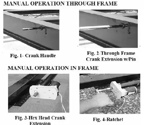
Schwentke In-Wall Slideout System
The in-wall slideout system requires no maintenance or adjustments. This system has two vertical columns with a drive motor located at the top of each column. The right and left motors are synchronized by a circuit board.
NOTE:
Do not operate the switch after the room is fully extended or retracted as damage can occur to the motor and/or switch.
To operate the slideout using a wireless remote (if so equipped):
- Press the on/off button to power on the remote.
- Press the corresponding button of the slideout you want to operate.
- Press and hold the (extend/retract) arrow button to move the room in or out.
- Press the on/off button once more to power off the remote.
ALWAYS allow the controller to stop both motors before releasing the switch button. DO NOT try to time the end of the stroke by releasing the button early.
Maintenance
Warning
Do not work on your system unless the 12-volt DC (auxiliary battery) and 120-volt AC electrical systems (shore line power cord) have been disconnected.
This slideout system requires very little maintenance. It contains a pre-lubed bearing that is lubricated when the room is moved in and out. Do not spray oil or grease on the rails while the room is extended.
Troubleshooting the in-wall slideout system
Checking Fuses:
The in-wall slide requires a minimum 30-amp fuse. Check the load center for blown fuses and replace any if necessary. If the fuse blows immediately upon replacement, there is a problem with the wiring to the in-wall slide control box. A qualified service person should be called to check and repair it.
Obstructions:
Check both inside and outside for possible obstructions. Also, check for smaller objects that may be wedged under the floor or in the sides of the unit. Remove any obstructions before proceeding.
Error Codes:
Refer to the error codes section for codes and instructions on how to locate the in-wall slide controller.
Low Voltage:
The in-wall slide controller can operate with as little as 8 volts; however, with lower voltages, the amperage requirement is greater. Check the voltage at the controller and if it is lower than 11 volts, it is recommended that the battery be placed on a charger until it is fully charged. It may be possible to “jump” the RV battery temporarily to extend or retract the room. Consult Customer Service before attempting to “jump” the auxiliary battery.
Only 1 Side Moving: The slide room has a separate motor to operate each side of the room. If only one side is moving, with another person’s assistance, press the switch to extend or retract the room while pushing the non-moving side in the appropriate direction. On larger rooms it may be necessary to have 2 or more people pushing the room. Non-moving side moved manually: Try to push the non-moving side in and out. If a motor shaft has broken it will be possible to move that side of the room several inches by hand. Larger rooms may require several people to push. Debris in the rack: Check all 4 gear racks on the side of the room for debris.
Status LEDs lights:
Locate the slide controller for the slideout in question. Check the status LED lights while pressing the slideout direction switch (in both the extend and retract mode).
Read all Instructions for Flush Floor Slideout User Manual
Jayco Eagle Fifth Wheels 2023 Manual override for in-wall slideout User Manual
2023 Jayco Eagle Fifth Wheels Manual override for in-wall slideout
Manual override for the in-wall slideout
The slideout system comes with an “electronic” manual override. In the event, the slide-out does not extend or retract follow these steps to override the system which should allow the slide-out to be retracted.
NOTE:
Fuses for the slideouts can be found in the load center and may be designated as auxiliary or slideout motors.
- Locate the slideout system controllers. There should be one for each slideout on the recreation vehicle. They are typically located on the forward wall or ceiling of a basement compartment. In some models, they may be behind a cargo-lined panel.
- The malfunctioning controller should have a flashing red LED indicating a halt signal fault (will flash 8 or 9 times).
- Press the “mode button” six times quickly, then press a seventh time and hold for approximately 5 seconds.
- The red and green LEDs will flash indicating you are in override mode. Release the mode button.
- Using either a wall or command center panel switch, press and hold the switch toward the word IN or RETRACT until the unit comes in completely. This will allow you to get the recreation vehicle to a service center to have the slideout malfunction diagnosed.
Caution
Call your dealer or Customer Service if:
- During the override procedure, the motors are not synchronized. Visually watch the room, and if one side is moving significantly slower than the other (or not at all).
- If the system stalls out before reaching the end of the stroke OR if the room does not close and seal tightly.
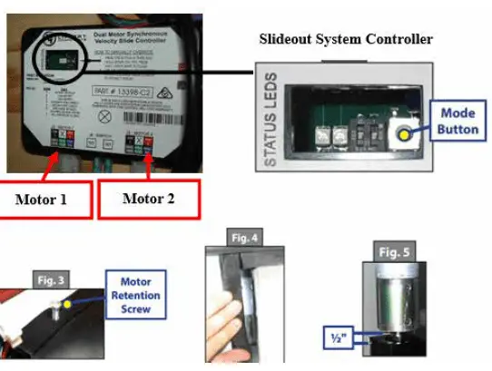
Manually pushing in the slideout
- Locate the slideout system controller.
- Unplug motor 1 and motor 2 connectors at the bottom of the slideout controller. This releases the motor brakes for each motor.
- The slideout room can now be manually pushed in. Larger rooms may require several people to push or pull them.
- Keep both sides of the slideout relatively even while pushing/pulling.
- When the room is completely in, plug both motor connectors back into the control module. This will apply the motor brakes for road travel.
Disengage motors, manually retract the room and travel lock
- Locate and remove the motor retention screw, which can be found near the top of each vertical column (Fig. 3).
- Bend back the wipe seal and visually locate the motor (Fig. 4).
- Pull the motor up until it disengages (about 1/2 inch).
- Repeat this process for both sides of the slide room.
- Physically push/ pull the room back into the opening; keep both sides relatively even.
- The room must be travel locked to keep the room in place for road travel.
Warning
DO NOT MOVE THE RV UNLESS THE MOTORS ARE PLUGGED IN TO THE CONTROLLER AND THERE IS BATTERY POWER TO THE RV. THIS SETS THE BRAKES ON THE SLIDEOUTS TO PREVENT THEM FROM MOVING DURING TRANSIT.
Error Codes
When an error code occurs during operation, the board LEDs lights will indicate where the problem is. For motor-specific faults the green LED will blink (1) time for motor #1 and (2) times for motor #2. The red LED will blink 2 to 9 times depending on the error code.
Error codes are as follows:
- 2 times Battery capacity is low enough to drop below 6 volts while running. 3 times Battery (low) voltage is below 8 volts at the start of a cycle.
- 4 times Battery (high) voltage is greater than 18 volts.
- 5 times Excessive motor current (high amperage) also indicated by (1) side of the slide continually stalling.
- 6 times Motor short circuit: motor or wiring to motor has shorted out.
- 8 times Hall signal not present: encoder not providing a signal; usually a wiring problem.
- 9 times Hall power short to ground: the power to encoder has been shorted to ground; usually a wiring problem.
The board will need to be reset after an error code. Energizing the extend/retract switch will reset the board; energizing it a second time will return it to normal operation.
Refer to the Schwintek Slide Room Operation Guide for additional troubleshooting information, or contact Lippert at (866) 524–7821 or at www.lci1.com.
Norco Slideout System
The Norco slideout system is a cable-driven slide-out used typically on towable products.
- The cables guide the room in or out, while the Accu-Slide mechanism evenly powers the corners keeping the room square.
- Motors and cables are behind the interior fascia board around the slideout opening.
- Cables may stretch over time. The average stretch will be approximately 1/8” but it will not affect the function and does not require adjustment.
- Slideout runs off the DC power in the RV.
- Rubber wipes prevent debris from entering the unit and actuation guides the bulb seals to close tightly.
- The self-locking motor freezes the room in any position of travel.
- Slideout is supported by rollers or wear bars not the cables. Cables are used to keep the slideout balanced on the rollers.
- If the room will not activate, generally there is no 12V power to the drive motor. The motor is equipped with a hex drive override shaft. This drive can be activated using an electric drill and the flexible shaft provided with each unit (or use a ratchet to actuate the motor) to pull the room in or out. If the motor is functioning, check the room for obstructions.
Norco Slideout Manual Operation
- Locate the included flexible shaft in your owner’s packet.
- Attach the flexible shaft to the 1/4” hex fitting on the end of the motor.
- Attach 1/4” socket & ratchet, or drill to the other end, and turn in the proper direction to move the room.
- If the cables tighten, and the motor is difficult to turn, REVERSE THE DIRECTION. OVER-TORQUEING CAN HAPPEN, RESULTING IN SEVERE DAMAGE.
Read all Instructions for Manual override for in-wall slideout User Manual
Jayco Eagle Fifth Wheels 2023 Power Gear Slideout User Manual
Jayco Eagle Fifth Wheels 2023 Power Gear Slideout User Manual
Power Gear Slideout System
Manual Override – The slideout system is equipped with a manual override that allows you to extend or retract the room in the event of a loss of power.
Caution
- Always disconnect the battery from the system prior to manually operating the system. Failure to disconnect the battery can cause electricity to back feed through the motor and cause serious damage to the system as well as void the warranty.
- Use EXTREME CAUTION when extending/retracting the room using the manual override feature. The gears can be stripped out if the room is manually retracted/extended to its fullest extent and the operator continues to rotate manually override. Damage can also occur to the slide components, slide room structure or trim components. Damages due to misuse of the manual override feature will void any and all claims to the Limited Warranty.
If the room does not move when the switch is pressed, check the following:
- Make sure the slideout system is turned on.
- The battery is fully charged and connected.
- Transit bars have been removed (if so equipped).
Warning
When the motor brake is disengaged the slideout room WILL NOT lock into place and will not be sealed. When the room has been manually retracted, be sure to install transit bars (if so equipped) and return the motor brake lever to its normal engaged position in order to seal and lock the room into position.
If the room still does not move when the switch is pressed, follow the steps below to manually override the slideout room:
- Turn the Main Power OFF. The override will not work if it has power going to it. Do not work on the system unless the battery is disconnected.
- Locate the slideout controller. There are two versions of the controller.
- Version 1, unplug the 6 pin wiring harness from the controller.
- Version 2, remove one of the motor leads, either the motor I or motor II lead from the controller.
- Locate the slideout motor (Fig. 1) mounted to one of the slideout rails. Some models may require removal of the underbelly or cover to access the motor. In a bedroom slideout, it may be located under the bed.
- Rotate the brake lever, on the backside of the motor, counter-clockwise (looking from the rear of the motor) about 1/8 of a turn to the released position (Fig. 2). This will release the brake that holds the room in the place.
- Locate the manual override for the slideout system (Fig. 1).
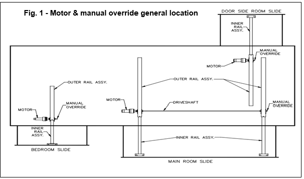
- The room is now free to move. Using either a 5/8” or 3/4” wrench or socket, crank the room either in or out completely. If the slideout system is supplied with a gearbox override (optional), use the crank handle to move the room.
- When the rooms is fully in or out have one person apply pressure to the wrench/ratchet and return the brake lever to its engaged position. This ensures the room is locked into a seated position.
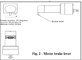
- Install the transit bars (if so equipped) to the slideout room and take the unit to an authorized dealer for service.
Refer to the Power Gear® Electric Slideout Operation Manual for detailed operation, safety and troubleshooting information.
Power Gear Slim Rack Slideout System
The Power Gear® Slim Rack slideout is typically used for slideouts 144” long and longer.
- It is operated by a 12VDC electric motor.
- The system is equipped with a manual override allowing the room to be extended/retracted in the event of a power loss.
- The system has a controller (Fig 1) with programmable stops that stop the motor when the room is fully extended or retracted.
- The controller has the ability to detect faults for easier troubleshooting.
- A wall-mounted touchpad allows room movement and provides end-user feedback.
When the motor brake is disengaged the slideout room WILL NOT lock into place and will not be sealed. When the room has been manually retracted, be sure to install transit bars (if so equipped) and return the motor brake lever to its normal engaged position in order to seal and lock the room into position.
Read all Instructions for Power Gear Slideout User Manual
Jayco Eagle Fifth Wheels 2023 Operating Slideout User Manual
Jayco Eagle Fifth Wheels 2023 Operating Slideout User Manual
Operating the Slideout
The slideout will not function until the stops are properly set or faults are cleared. A solid “ON” GREEN LED indicates room movement.
The RED LED indicates a fault or a problem with the system. (Refer to the Fault Diagnostics / Troubleshooting).
Prior to moving the slideout room set the parking brake.
To ensure ample voltage is being supplied to the slideout system motor, power should be supplied from one of the following sources:
- Attach the RV to shore power.
- Have the motor home engine running.
- Turn on the generator.
Extending/retracting the room
- Engine or generator must be running, or plugged into shore power.
- Transmission must be in park or neutral (if applicable).
- Set the parking brake and level the unit.
- Remove transit bars (if so equipped) if extending the room; install if retracting.
- Turn ON the on/off switch or key.
- Press and hold the OUT button. To retract, press and hold the IN button. There will be a slight delay before the room begins moving.
- The GREEN LED should be solid ON when room is in motion.
- Release the OUT button when the room is fully extended or the IN button when fully retracted, and stops moving.
- Turn OFF the on/off switch or key.
Fault Diagnostics / Troubleshooting
The control has the ability to detect and display several faults. When a fault is detected, room movement stops and two different LEDs will flash in a pattern.
The RED FAULT CODE LED will flash a number of times corresponding to a specific fault code (refer to the Fault Code Chart).
The GREEN ROOM MOVEMENT LED will flash GREEN a number of times corresponding to which motor has the associated fault.
Example: (4) RED flashes and (2) GREEN flashes indicate a motor fault on motor 2.
MAJOR and MINOR faults; faults must be cleared for the room to operate normally.
- MINOR faults can be cleared by pushing and releasing the IN or OUT buttons on the wall touchpad.
- MAJOR faults must be cleared by pushing and releasing the SET STOPS/CLEAR FAULTS button located on the back of the wall touchpad.
NOTE:
For MAJOR faults, the control must be overridden by following the EMERGENCY RETRACT MODE in the OVERRIDE MODES section.
| Fault Code | Fault Type | Fault Codes | ||
| Description | Possible Cause | Possible Solution | ||
|
1 |
Major |
Stops not programmed |
|
Steps need to be pro grammed by an authorized service facility. |
|
2 |
Minor |
System Fault |
|
Run room in opposite direction. If it continues to move in the opposite direction, remove obstruction, excessive weight in room or repair of damaged component. If room stops moving in opposite direction, observe fault code and refer to this chart |
|
4 |
Major |
Excessive Battery Voltage |
|
|
|
Park brake LED flashing |
|
|
||
|
6 |
Minor |
Supply voltage to control box is 17 0 V DC or greater |
Check 2-pin power connector at control box. If the voltage is 17. VDC or higher, contact
O.E.M for power and ground supplies |
| Park brake LED flashing |
|
|
| Low voltage LED flashing | Incoming violated to control box is below
12.0 VDC |
Check 2-pin power connector at control box. If voltage is below 12.0 VDC contact
O.E.M for power and ground supplies. |
Preventative Maintenance
The Power Gear® slideout system requires very little maintenance. Read and follow these procedures:
- When the room is extended, visually inspect the slide rail assemblies. Check for the excess buildup of dirt or foreign material; remove any debris that may be present.
- If the system squeaks or makes any noises, blow out any debris from the gear rack arms and apply a dry lubricant to prevent and/or stop squeaking.
Refer to the Power Gear® website www.powergearus.com for additional information.
Override Modes
In the event of component failure or loss of system power, your slideout can be manually overridden and retracted for travel.
Read all Instructions for Operating Slideout User Manual
Jayco Eagle Fifth Wheels 2023 Emergency Retract Mode User Manual
Jayco Eagle Fifth Wheels 2023 Emergency Retract Mode User Manual
Emergency Retract Mode
Use this procedure when there is NO loss of power or electrical problem with the system.
- Remove the touchpad (Fig 4) from the wall.
- Prior to clearing the MAJOR fault, record the number of RED & GREEN flashes observed on the touchpad (Fig 6).
This information will help your dealer/service center in troubleshooting the slideout system. - Press and hold the SET STOPS/CLEAR FAULTS button on the back of the touchpad for five (5) seconds (Fig 2). Both RED & GREEN LEDs will be on solid while pressing this button. After 5 seconds, the GREEN LED will begin flashing and the RED LED will remain solid on.
- The unit is now ready to retract the room. Press and hold the ROOM SLIDEOUT MO-TOR buttons 1 and 2 on the back of the touchpad (Fig 3).
Caution
It is very important to note that during this procedure, the slideout control has NO stop locations. Use a second person to assist in determining when the room is retracted. Damage to the room can occur if the room is retracted too far. - Press the IN button on the front of the wall touchpad until the room is fully retracted. If one side of the room needs to retract further in order to get a good seal, press and hold the motor button corresponding to ONLY the motor you want to move. Press the IN button on the front of the touchpad to retract the room the remainder of the way.
- Re-install the wall touchpad.
- Take the unit to an OEM-certified dealer for repairs.
Manually Retract Room with Ratchet and Socket If the power is lost to the slideout motor(s) or the override mode above will not work, the room may be manually retracted using a ratchet and socket attached to the end of the coupler.
- Gain access to the VERTICAL CHANNEL assembly from inside or outside of the coach (whichever is more convenient). Remove the trim and flange pieces on the slide-out room box.
- If applicable, remove the top screw from the bulb seal at the top of the VERTICAL CHANNEL (Fig 8).
- Pull down the bulb seal and remove the motor cover (Fig 9). The motor seal may stick to the bulb seal.
- Using a pick tool, remove the end of the retaining spring from the motor spring clip (Fig 10A). If not equipped with a retaining spring, loosen the motor retaining screw (Fig 10B).
- Unplug the motor from the harness and remove the motor by lifting it up and out.
- Repeat steps 1-4 for the other side.
- Place a socket wrench with a 3-inch extension and a 5/8” deep well socket (Fig 12) through the motor access opening and seat the socket onto the coupler (Fig 13). One person alternating from side to side of the room can retract a 1500 lb. room with or without a ramp.
- NOTE:
One person on each side of the room with a ratchet and socket will expedite the process. Room moves ¼ inch for every 30 to 40 degree turn of the wrench.
- NOTE:
- Secure the room in place by either:
- Re-installing the motors (making sure the end of the retaining screw is re-hooked to the motor spring clip (Fig 10A).
- Torque the motor retaining screw to 40 inch/lbs. (Fig 10B) and the motor retainer is fully engaged.
- Use a travel lock (a 2×4 cut to size) etc.
- Refer to Fig 10A and 10B for proper seating of the motor.
- Have the slideout room serviced by an OEM-authorized dealer as soon as possible. Do not operate the room until service is complete as damage to the room may result.
Manually Retract Room with Ratchet and Socket If the power is lost to the slideout motor(s) or the override mode above will not work, the room may be manually retracted using a ratchet and socket attached to the end of the coupler. Press the IN button on the front of the wall touchpad until the room is fully retracted. If one side of the room needs to retract further in order to get a good seal, press and hold the motor button corresponding to ONLY the motor you want to move. Press the IN button on the front of the touchpad to retract the room the remainder of the way.
Read all Instructions for Emergency Retract Mode User Manual
Jayco Eagle Fifth Wheels 2023 Power Gear Ram Slideout User Manual
Jayco Eagle Fifth Wheels 2023 Power Gear Ram Slideout User Manual
Power Gear Ram Slideout System
Manual Override Procedure
The system has been equipped with 3/4” hex override couplers located on the drive component of the system. Due to the size and weight of some rooms, assistance may be needed to push the room in.
Use the following steps to mechanically operate the room.
- Locate the ABS motor access cover for the slideout.
This cover will be located inside one of the storage compartments under the slide room up at the top of the compartment. - Remove (4) screws holding the panel to the top of the compartment. Remove the cover.
- Unplug the motor leads at the connector. Gray connector with red and black wires.
- To release the motor brake you must depress the spring lock lever, which then allows you to pivot the brake lever, which in turn releases the brake. These parts are located inside the rubber boot wire tied over the motor. You must manipulate these parts without removing the rubber boot. As noted on the side-by-side photo, removing this boot will void your motor warranty. These photos will help you figure out how this works. The side-by-side photo (below) shows the spring lock lever and the brake lever.
- The spring lock lever is a thin metal arm with a slight bend at the end, which will hold the brake lever in the released position.
- The brake lever is the heavier thicker metal arm with the hole in the end.
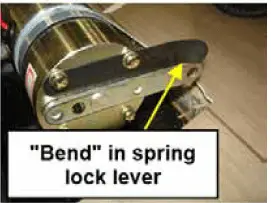
- The normal position for these two levers is to be parallel to each other as shown in the first side-by-side photo.
The motor brake is engaged with levers side by side. - The brake lever is moveable; the spring lock lever is not moveable. To release the brake lever, you must push the bent end of the spring lock lever away from the brake lever; this will allow you to pivot the brake lever so it moves over on top of the spring lock lever. The bent end will hold the brake lever in the released position. (photo shows this “bend”).
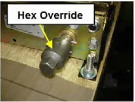
- Once the brake motor is released, you will need to re- move the skirting on the side of the slideout floor where the hex override is located.
- Use a ratchet with a 3/4” socket (or wrench) to turn the hex override and manually move the slideout.
- When the slideout is retracted, check to make sure you have a good seal, and re- place the skirting on the slideout.
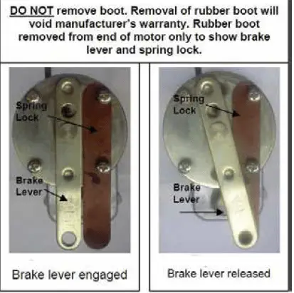
- Return the brake release lever back to the “engaged” position (parallel to the spring lock lever). Pressing the bent end of the spring lock lever will allow the brake lever to be moved.
- Plug the motor connector back in again.
- Replace the plastic motor cover with the (4) screws removed previously.
- Take the unit to an authorized dealer for service.
For further information, refer to the manufacturer’s owner’s manual.
The Electrical System
The RV electrical system is comprised of two independent electrical systems. One operates off of 12-volt DC power and the other off of 120-volt 60hz AC power. All installations have been made in compliance with industry standards applicable on the date of manufacture. Because the electrical equipment and associated circuitry are engineered into a dedicated system specific to your RV, do not make unauthorized changes or add fixed appliances to it. Changes or additions made after delivery may result in a hazardous condition. Service and/or modification of the electrical system should only be performed by qualified electrical technicians using approved materials, components, and methods meeting current safety and code requirements. Consult your dealer’s service department for assistance. To read more about the various components incorporated into the RV electrical system, please refer to the information contained in your Warranty Packet. For motorized vehicles, consult the Chassis Guide for information pertaining to the chassis drivetrain electrical system.
Electrical System Maintenance
Before working on the electrical system:
- Make sure the inverter/charger (if so equipped) is turned “off” before disconnecting batteries. Disconnect the shore power cord.
- If equipped with a generator, turn off the generator and disable the automatic generator start functionality.
- Turn off the battery disconnect switch (if so equipped).
- Turn off the 120V main circuit breaker.
- Disconnect the negative 12VDC battery terminal from the battery.
Warning
Use caution when using metal tools. If a tool contacts a battery terminal or metal connected to it, a short circuit could occur which could cause personal injury, explosion, or fire.
Read all Instructions for Power Gear Ram Slideout User Manual
Jayco Eagle Fifth Wheels 2023 Command Center User Manual
Command Center
The command center is typically located inside the entrance door or in the living area of the RV, and contains switches and controls. Command center applications, configurations, and components may vary by model. Command Center Panel or Command Center Panel with Switch Modules
Items found on these panels may include:
- Fuel gauge and hour meter with switches for fuel pump and fuel levels; fuel station (if so equipped) on/off switch
- Lighted red pump and water heater switches (electric and LP gas)
- Generator start/stop switch; may include an hour meter
- Tank heater switches Light switches for porch lights, exterior security lights, interior lights, awning LED lights, front cap LED accent lights, power entry step
- Cargo bed red lighted control switch
- Slideout control switches (press and hold to extend / retract)
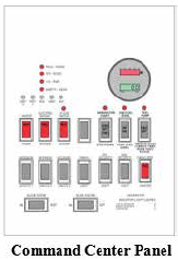
- Awning control switches (press and hold to extend / retract)
- Systems Monitor with LED indicators for tank levels and battery charge status
- Auto leveling control panel (for leveling the RV)
- Inverter panel (power switch with display)
- Power bunk bed lift control switch
- Speaker selector switch.
Touch Dimmer Switch
Some models may include a touch dimmer switch next to the Command Center panel.
- Turn the ceiling lights ON or OFF: Tap the LED light on the dimmer.
- Dimmer: If lights are off, press on the LED light and lights will begin turning on gradually until fully lit. If lights are on, press on the LED light and lights gradually begin to turn off.

The dimmer has a memory and remembers what light setting was last used. When turned ON again, the lights return to that setting.,
NOTE:
If your RV model includes the 5-way/8-way remote control, the LIGHT button on the remote only controls the awning LED lights.
GFCI Receptacle
There is a ground fault current interrupter (GFCI) engineered into the electrical system. It is designed to reduce the possible injury caused by electric shock. The GFCI will not protect against short circuits or circuit overloads.
Test all GFCI receptacles monthly
- Push in the GFCI “TEST” button. The GFCI “RESET” button should pop out indicating the GFCI receptacle has been “tripped” and interrupted 120-volt power.
- Push in the GFCI “RESET” button to restore 120-volt power.
Contact your independent dealer for assistance if the GFCI “RESET” button does not restore 120-volt power and pops back out.
- A “tripped” GFCI breaker indicates that an abnormally high 120-volt current flow (a ground fault) was detected. All ground faults must be repaired before the use of the recreation vehicle.
Command Control System (if so equipped)
The Command Control System encompasses several types of Bluetooth-controlled systems in your Recreation Vehicle.
The Command Control System is capable of controlling some or all of the following features depending on the Bluetooth system and your model:
| RV Auto Leveling System | Power Jacks and Stabilizers |
| Interior and Exterior Lighting | RV Slideout Rooms |
| Power Awnings | Generator |
| TV and Bed Lifts | HVAC Thermostat |
| Gas and Electric Water Heaters | Water Tank Levels (black, gray, fresh) |
| Battery Levels | Back Up Camera Systems |
| Water Pump | Kitchen and Bath Vents and Covers |
| Door Locks | TV, Radio and DVD Systems |
| Automatic Fireplace Control | Automatic Ramp Door (Toy Hauler) |
| Propane Sensor | Temperature Sensor |
NOTE:
On some systems, the switches are turned on with a Control App or the touchscreen override switches at the command center panel. If a device is turned on with the app or the touchscreen and then the touchscreen or the app were to fail, that device would not be able to be turned off using the command center panel switches. To regain command center panel control, battery power would need to be disconnected from the RV to reset the system. This can be done by turning off the Battery Disconnect switch or removing the power cable from your battery, then turning the Battery Disconnect switch back on or re-attaching the battery cable.
Read all Instructions for Command Center User Manual
Jayco Eagle Fifth Wheels 2023 BMPRO RVMaster System User Manual
Jayco Eagle Fifth Wheels 2023 BMPRO RVMaster System User Manual
BMPRO RVMaster System
The following is an overview of the BMPRO system.
Refer to the BMPRO RVMaster user guide for complete operating, setup, and programming instructions. A digital version of the operator manual may be included with the system. On the HOME screen (upper right corner) press the SETTINGS button (the small Gear icon) and scroll the screen down until you see USER MANUAL. Tap to open. To return to the beginning, tap the screen and a drop-down appears at the top of the screen. Select the back arrow at the top left to return to the menu screen. To get back to the display HOME screen, press the left-facing triangle button at the bottom of the screen.
The RVMaster Bluetooth touchscreen is a wall-mounted control giving you the freedom to operate multiple RV functions from one location inside the RV.
The touchscreen and remotes connect to the RVMaster Node via Bluetooth. The RVMaster Controller (touchscreen) has Wi-Fi capabilities to connect to the internet to download the latest app updates. The system has a downloadable app available for your smartphone, tablet or smart device called RVMaster.
The following list describes some of the features this system may control. Depending on your model or system, not all of these features will be available.
- RV auto-leveling systems
- Power jacks and stabilizers
- Interior and exterior lights
- RV slide-out rooms
- Power awnings
- Generator
- TV and bed lifts
- HVAC thermostat
- Gas and electric water heaters
- Freshwater, black water, and gray water tank levels
- Battery levels
- Back-up camera systems
- Water pump
- Kitchen and bath vents and vent covers
- Door locks
- TV, radio, and DVD systems
- Automatic fireplace control
- Lowering/raising the automatic ramp door (toy hauler)
RVMaster Switches (remote controls)
The system will come with multiple individual smart remote controls (or RVMaster Switches). Depending on your floor plan or system, these can be programmed for individual room control. The remotes are installed on the wall in each room.
Pairing the remote controls
Remote controls come from the factory paired to your system. If remotes get “un-paired” from the RV Bluetooth system, press the arrow keys at the bottom of the touchscreen until PA appears in the Menu Display. Press the RET button and the display will blink on and off indicating the system is ready for pairing. Press and hold any two buttons on the remote control. The PA display will go out when the pairing is complete. The remote will now be able to operate the systems labeled on the individual buttons for that specific room and remote.
Remote Batteries
The RVMaster Switch remote controls use a 3V Lithium CR2032 coin cell battery.
To access the battery on the back of the remote, remove the remote from the wall:
- Pull the bottom of the remote away from the wall. There will be an audible snap as it releases from the clip.
- Lift the remote upwards to unhook it at the top.
- The remote will separate from the wall mount.
To replace the remote on the wall:
- Hook the top of the remote on the top of the wall bracket.
- Push the bottom of the remote back in place. There will be an audible snap as it attaches to the mount.
Touchscreen Control Panel
The row of buttons at the bottom of the touchscreen control certain pre-programmed features and allow control of the slideouts, awnings, lights and water pump. In the event the touchscreen is not working, this Control Panel will allow manual operation separate from the touchscreen.
NOTE:
- Buttons #1 through #4 are pre-programmed from the factory and cannot be changed to perform other functions.
- Button #1 – Turns all interior lights ON or OFF. Press once for ON, and press again for OFF.
- Button #2 – Turns all outside lights ON or OFF, which include security lights, awning lights, and ramp door lights (toy hauler). It does not operate the front cap LED lights. Press once for ON, and press again for OFF.
- Button #3 – Turns inside and outside lights ON or OFF. Press once for ON, and press again for OFF.
- Button #4 – Turns water pump ON or OFF. Press once for ON, and press again for OFF.
- Arrow Buttons – Used to select awnings or slideouts, pair your smartphone or tablet to the touchscreen system, pair the dedicated remotes, or to turn the touchscreen display OFF.
- RESET Button – There is a small pinhole above the left arrow on the Menu Display that will reset the touchscreen.
- EXT Button – Used to extend either slideouts or awnings. Used in conjunction with the arrow buttons to select an awning or slideout (also used when pairing your smartphone or tablet to the system).
- RET Button – Used to Retract either slideouts or awnings. Used in conjunction with the arrow buttons to select an awning or slideout (also used when pairing wall-mounted remotes to the system).
Menu Display (between arrow buttons) uses the arrow keys to scroll through the selections.
- Menu Display shows A1 or A2 (awnings). Cycle between awnings with the arrows. Press and hold EXT or RET to extend or retract the selected awning.
- Menu Display shows b1 or b2 (bunk lifts).
- Cycle between bunk lifts with the arrows press EXT or RET to operate.
- Menu Display shows J1, J2, J3 or J4 (jacks).
- Cycle between jacks then press EXT or RET to operate.
- Menu Display shows S1, S2, S3 or S4 (slideouts).
- Cycle between slides using the arrow buttons. Press and hold EXT or RET to extend or retract the selected slideout.
- Menu Display shows OF (must then press the EXT button) to turn off all loads (lights and fans plus touchscreen). This does not shut down the generator. Press any of the numbered light buttons to turn the touchscreen back on.
- Menu Display shows PA (pair). Press EXT to pair your phone or tablet or press RET to pair one of the wall-mounted remote controls. The PA on the small display will flash on and off indicating the system is in pairing mode and can be connected to a Bluetooth smart device. When the device is paired, the PA display will go out.
Read all Instructions for BMPRO RVMaster System User Manual
Jayco Eagle Fifth Wheels 2023 Turning on touchscreen User Manual
Turning on the touchscreen system
The touchscreen system automatically boots up when power is turned ON to the RV.
If the touchscreen system requires a reset, or if the touchscreen has been turned off:
- Pressing either of the arrow keys, or a numbered key will turn the system ON (EXT or RET keys will not turn on the system).
- Two splash screens with the BMPRO logo will appear first during boot-up.
- To go to the RV Master touchscreen, press the icon for the touchscreen (or let the bootup process finish).
- The RV Master touchscreen is now active and ready to use.
NOTE:
Pressing the RESET button on the touchscreen will also reboot the touchscreen.
Pairing a smart device to the RV Master app
Download and install the BMPRO RV Master app from the Google Play Store or the Apple App Store. When the app is started, press the Menu Display arrow keys until the small display shows PA. Then press the EXT button to put the system in pairing mode. Open the Bluetooth setting on your phone and select “RVGenius” in the list of devices available. Once connected this app will control the devices in the RV. Up to (3) personal Bluetooth devices can be connected to the RVMaster system. Only (1) one device at a time can be paired.
NOTE: The RVMaster Motors screen automatically locks on your smart device after connecting to the app to prevent inadvertent operation of the sys-tems in the RV. The lockout indicator on the screen must swipe to unlock the motor controls. When operating any motor control, the system locks out all other control devices (e.g. smartphone or command panel) until the motorized device in use has stopped.
Electrical System
- Kitchen and bath vents and vent covers
- Door locks
- TV, radio and DVD systems
- Automatic fireplace control
- Lowering/raising the automatic ramp door (toy hauler).
RVMaster Switches (remote controls)
The system will come with multiple individual smart remote controls (or RVMaster Switch-es). Depending on your floor plan or system, these can be programmed for individual room control. The remotes are installed on the wall in each room.
Pairing the remote controls
Remote controls come from the factory paired with your system. If remotes get “un-paired” from the RV Bluetooth system, press the arrow keys at the bottom of the touchscreen until PA appears in the Menu Display. Press the RET button and the display will blink on and off indicating the system is ready for pairing. Press and hold any two buttons on the remote control. The PA display will go out when the pairing is complete. The remote will now be able to operate the systems labeled on the individual buttons for that specific room and remote.
Remote Batteries
The RV Master Switch remote controls use a 3V Lithium CR2032 coin cell battery.
To access the battery on the back of the remote, remove the remote from the wall:
- Pull the bottom of the remote away from the wall. There will be an audible snap as it releases from the clip.
- Lift the remote upwards to unhook it at the top.
- The remote will separate from the wall mount.
To replace the remote on the wall:
- Hook the top of the remote on the top of the wall bracket.
- Push the bottom of the remote back in place. There will be an audible snap as as it attaches to the mount.
Touchscreen Control Panel
The row of buttons at the bottom of the touchscreen control certain pre-programmed features and allow control of the slideouts, awnings, lights and water pump. In the event the touchscreen is not working, this Control Panel will allow manual operation separate from the touchscreen.
- NOTE: Buttons #1 through #4 are pre-programmed from the factory and cannot be changed to perform other functions.
- Button #1 – Turns all interior lights ON or OFF. Press once for ON, and press again for OFF.
- Button #2 – Turns all outside lights ON or OFF, which include security lights, awning lights, and ramp door lights (toy hauler). It does not operate the front cap LED lights. Press once for ON, press again for OFF.
- Button #3 – Turns inside and outside lights ON or OFF. Press once for ON, press again for OFF.
- Button #4 – Turns water pump ON or OFF. Press once for ON, press again for OFF.
- Arrow Buttons – Used to select awnings or slide outs, pair your smart phone or tablet to the touchscreen system, pairing the dedicated remotes, or to turn the touchscreen display OFF.
- RESET Button – There is a small pinhole above the left arrow on the Menu Display that will reset the touchscreen.
- EXT Button – Used to extend either slide outs or awnings. Used in conjunction with the arrow buttons to select an awning or slide out (also used when pairing your smart phone or tablet to the system).
- RET Button – Used to Retract either slideouts or awnings. Used in conjunction with the arrow buttons to select an awning or slide out (also used when pairing wall-mounted remotes to the system).-
Menu Display (between arrow buttons) use the arrow keys to scroll through the selections.
- Menu Display shows A1 or A2 (awnings). Cycle between awnings with the arrows. Press and hold EXT or RET to extend or retract the selected awning.
- Menu Display shows b1 or b2 (bunk lifts).
- Cycle between bunk lifts with the arrows press EXT or RET to operate.
- Menu Display shows J1, J2, J3 or J4 (jacks).
- Cycle between jacks then press EXT or RET to operate.
- Menu Display shows S1, S2, S3 or S4 (slide outs).
- Cycle between slides using the arrow buttons. Press and hold EXT or RET to extend or retract the selected slide out.
- Menu Display shows OF (must then press the EXT button) to turn off all loads (lights and fans plus touchscreen). This does not shut down the generator. Press any of the numbered light buttons to turn the touchscreen back on.
- Menu Display shows PA (pair). Press EXT to pair your phone or tablet or press RET to pair one of the wall-mounted remote controls. The PA on the small display will flash on and off indicating the system is in pairing mode and can be connected to a Bluetooth smart device. When the device is paired, the PA display will go out.
Turning on the touchscreen system
The touchscreen system automatically boots up when power is turned ON to the RV. If the touchscreen system requires a reset, or if the touchscreen has been turned off:
- Pressing either of the arrow keys, or a numbered key will turn the system ON (EXT or RET keys will not turn on the system).
- Two splash screens with the BMPRO logo will appear first during boot-up.
- To go to the RVMaster touchscreen, press the icon for the touchscreen (or let the bootup process finish).
- The RVMaster touchscreen is now active and ready to use.
NOTE Pressing the RESET button on the touchscreen will also reboot the touchscreen.
Pairing a smart device to the RVMaster app
Download and install the BMPRO RVMaster app from the Google Play Store or the Apple App Store. When the app is started, press the Menu Display arrow keys until the small display shows PA. Then press the EXT button to put the system in pairing mode. Open the Bluetooth setting on your phone and select “RVGenius” in the list of devices available. Once connected this app will control the devices in the RV. Up to (3) personal Bluetooth devices can be connected to the RVMaster system. Only (1) one device at a time can be paired.
Read all Instructions for Turning on touchscreen User Manual
Jayco Eagle Fifth Wheels 2023 LCI One Control App User Manual
Jayco Eagle Fifth Wheels 2023 LCI One Control App User Manual
LCI One Control App
The OneControl System is a Bluetooth-controlled system incorporating a touchscreen typically located inside the entrance door. This system will control certain systems within your RV through the use of the touchscreen such as awnings, the leveling system, lighting, slide-outs etc.
NOTE: The systems described are a typical representation of what you could see on your smart device. If specific apps are not displayed on your device they are not installed and may not be available for your RV.
The One Control System will not operate the hall light, lights located inside each slide-out, exterior amber/red marker lights, or the LED strip lights located on the front or rear caps.
Bluetooth Operation of the One Control® System
Refer to the One Control ® App section of this manual or the manufacturer’s user guide for information on using the Bluetooth app.
Touchscreen operation
The touchscreen has four selections on the left side of the screen: HOME, DEVICES, SET-TINGS, and HELP. There are also (3) touch buttons on the screen for lighting.
- DEVICES: The DEVICES button will bring up selections for slideouts, stabilizers, auto leveling or lighting. Pressing the LIGHTING button brings up choices for lights in the RV. These are the same lighting selections found on the HOME screen. Pressing the SLIDES button will open a selection screen showing all the slides on the RV. Selecting one of the slides will open another screen that has In and Out buttons (also labeled + and -). Pressing and holding either button will extend or retract the slide. The back arrow at the upper left returns you to the previous screen. Pressing the STABILIZERS button will open a selection screen showing available stabilizers. Selecting a stabilizer will open the control screen that allows you to retract or extend the stabilizers. Press the back arrow at the top left to go back to the previous screen. If your RV has Auto Leveling, refer to the OneControl Manual for detailed operating information.
- SETTINGS: The SETTINGS button will bring up selections for Diagnostics, Re-sync Devices, Units, Developer, and System Clock. Refer to the One Control manual for detailed operating information.
- HELP: The HELP button will bring up a link for an electronic version of the manual (or manuals) and any videos that may explain the operation of the system.
- For additional information on using the touchscreen system, refer to the manufacturer’s user guide.
LCI One Control® App(if so equipped)
Some models may include a Bluetooth control module that works with the LCI One Control App for your smartphone, tablet, or another smart device. When connecting to this app, certain systems in your RV can be controlled remotely from your smart device. This free app is available for download for your smartphone, tablet, or smart device.
NOTE: The systems described are only a typical representation of what you could see on your smart device. If specific apps are not displayed on your device they are not installed and may not be available for your RV.
Connecting to the Bluetooth Control module
A Bluetooth control module is mounted in the basement area of the RV. A Password and a Device Name are required for this Bluetooth connection. The Password and Device Name can typically be found on a label located inside a cabinet near the entrance door of the RV. The password and device name will also be located on a label on the control module in the basement area although this may not be easily accessible.
The password is (6) numerical digits. To connect: enable Bluetooth on your smart device, scan for available Bluetooth connections, and the Device Name will name appear as a connection. Select and it should prompt for the 6-digit password.
- Awning Operation: Select the AWNING icon, the screen opens showing the awnings. If there are multiple awnings, there will be a selection for each awning at the left of the screen. Select the awning you want to control, then press and hold the EXTEND (B) or RETRACT (C) buttons. Select the back arrow (A) to return to the previous screen
- Leveler Operation: Select the LEVELER icon, the screen opens showing the leveler control panel. This screen will allow you to extend and retract the jacks and to auto-level the RV. Press the AUTO LEVEL button (A) to begin leveling the RV. Refer to the Lippert User Guide for the One Control system for more detailed information. Select the HOME icon to return to the previous screen.
- Slide-out Operation: Select the SLIDES icon which will open the slide-out screen. The screen can display up to (4) slide-outs. Slide-outs will be numbered 1-4 on the touchscreen. Press Slide 01, and then press and hold the OUT (A) button to extend the slide or the IN (B) button to retract it. Repeat this action on the remaining slide-outs. Select the back arrow to return to the Device Selection screen.
IMPORTANT SAFETY FEATURE
If Slide 01 is missing from the list, this indicates a problem with the bedroom slide-out. In order for the slideout to function properly, the bedroom door MUST BE OPEN. An electronic door catch has been installed to the wall in the bedroom behind the door. A second piece is mounted to the door. If the door is closed, the Slide 01 notification on the touch-screen display will disappear and the slide-out will NOT operate. When the bedroom door is opened and the catch pieces connect, the Slide 01 notification will appear on the touchscreen display and the slide-out can then be operated normally.
NOTE: This same safety feature applies to the slide-out switch on the wall or on the Command Center switch panel. The bedroom door must be open and the catch pieces connected for the bedroom slide to work.
Operating the Lights: Select the LIGHTING icon and the Lighting Control screen opens allowing you to control lighting in your RV.To operate, scroll through the list and find the light you want. Individual lighting controls will appear on this screen. If the switch is ON, the light bulb for each item will illuminate. If the ALL ON switch is selected, all the lights shown on the screen will turn ON. Selecting ALL OFF turns all the lights OFF. The lights will light in steps to prevent a power surge. Light switches may have to be toggled twice for them to operate as this system is multiplexed with the command center panel and other wireless controllers in the RV. The One Control System will NOT operate the hall light, lights located inside each slide-out, exterior amber/red marker lights, or the LED lights located on the front or rear caps.
Inverter (if so equipped)
A factory-installed inverter converts 12-volt DC to useable 120-volts AC and supplies continuous AC power to the appliance plugged into it. It is important that you familiarize yourself with the inverter’s function and operation. The inverter should be “off” when not in use.
NOTE: The factory-installed inverter is not intended for use, nor should be used, with any medical device(s). The inverter may, however, be used with some CPAP machines, depending on the CPAP model. Consult your CPAP machine’s instruction manual before use to ensure proper operation.
If your recreation vehicle is equipped with a residential-style refrigerator, the inverter may be used to supply the 120-volts AC necessary to power the refrigerator.
Maintenance
There are no customer-serviceable parts inside the inverter case and the manufacturer’s warranty will be void if the case has been removed. The inverter cooling fins and the cooling fan should be kept clear of any obstructions.
Command Center Switch (if so equipped)
Your RV may have an inverter remote display on the Command Center switch panel. There are power and select buttons, Status/Display indicators and a single-line digital alpha-numeric display. The display can show measured battery voltage, AC output power, inverter settings, and error codes.
Refer to the Inverter manufacturer’s manual in your warranty packet for further operating instructions, error codes, changing inverter settings and safety information. The POWER button is used to turn the inverter on and off. To turn on the inverter and the LED display press and hold POWER for 1 second until you hear a beep.
NOTE: When in Inverter Mode you will be able to cycle through Battery Voltage, Inverter Power, inverter settings and error codes.
When in Bypass Mode you will be able to cycle through Battery Voltage, inverter settings, and error codes. Inverter Power will not be available because the inverter is idle.
The STATUS and DISPLAY indicators indicate the inverter status:
- STATUS & DISPLAY LEDS – both GREEN – Unit is plugged into shore power. The panel is in Bypass Mode and will display battery voltage in DC volts.
- STATUS LED AMBER, DISPLAY LED GREEN – Inverter Mode is active. Inverter is ON and will display battery voltage in DC volts (not connected to shore power).
- STATUS & DISPLAY LEDS – both AMBER – Inverter Mode is active. Inverter is ON, pressing the SELECT button will display the inverter power output. Display shows power output in KW.
- TATUS LED FLASHES AMBER, DISPLAY LED IS OFF – If the unit is in Inverter Mode, and you plug in shore power, the STATUS LED will begin flashing AMBER and the unit will switch to Bypass Mode within 20 seconds of detecting an AC input.
- If the STATUS LED is RED and the DISPLAY LED is OFF, the display will show an error code of E01 through E12. This indicates a fault in the inverter circuit that needs attention. Inverter will shut down.
Read all Instructions for LCI One Control App User Manual
Jayco Eagle Fifth Wheels 2023 Power Converter User Manual
Power Converter
The power converter converts 120-volt AC power to usable 12-volt DC power when the shore power cord is connected to an external power source.
The converter has a built-in protective thermal breaker that will shut it down should overheating occur. Overheating can be caused by operating the converter above its maximum power output for an extended period of time, or by an obstruction to its ventilation airflow. To reduce converter heat build keep unnecessary 12-volt lights and motors turned off. Keep the converter cooling fins and fan clear of obstructions.
- USE ONLY A DEEP-CYCLE BATTERY FOR RV USE. Car batteries (CCA rating) are not designed for RV applications.
- If using multiple batteries they must be the same brand and type. Adding more batteries will provide longer use of DC appliances when not on shore power but may reduce charging efficiency.
- The battery works in conjunction with the converter to supply DC power to the RV. A battery is typically only necessary if you do a lot of dry camping or have slide-outs and/or a leveling system.
- A reverse polarity fuse provides protection for the converter when a battery is used. If the battery is connected back to the fuse board this fuse would blow pre-venting damage to the converter.
- Dimming or flickering lights usually indicates an overloaded converter. Remove some of the load by turning off DC lights or appliances.
- Fan is controlled by load. It will begin running at 3 to 6 amp DC draw. It increases in speed with a higher load until 14 to 15 amps. The fan is at maximum speed and stays there even with more load. If the load drops below 6 amps DC, the fan shuts off.
CAUTION
It is important that the fluid level of any connected batteries be checked on a regular basis. All batteries will “gas” and lose some fluid when continuously connected to any charging source (does not apply to “gel-cell” batteries). Before checking for converter output voltage, the battery cables must be disconnected at the battery. Make sure the converter is plugged into an AC source (105-132 AC volts). Check the converter output voltage at the battery with a voltmeter. Place the voltmeter probes on the disconnected battery cables. If the voltage reads 13.6VDC with no load, the converter is functioning properly. If the converter output voltage at the battery reads in the 0.0VDC range, or the battery is not charging, check for:
- An open inline fuse in the battery wire
- An open wire between the converter and the RV battery
- Loose ground connection
- Improper torques
If the converter fuses and AC voltage are good, but the converter output still reads zero volts, the converter is not functioning properly.
Modes of Operation
Absorption (Normal) Mode: 13.6VDC range. Batteries are being charged, just at a slower rate. The converter will not work without AC input.
Float Trickle Mode: To get your converter into this mode, reduce the load on the system to almost nothing but the battery. Let the system sit for approximately 44 hours.
The converter voltage will drop to 13.2VDC. If the converter sees any load during this period or after it is in Float Mode it will revert back to Absorption (Normal) Mode. 13.6VDC.
Bulk Mode: The converter will not jump into the Bulk Mode unless the battery is below 50% of charge, or approximately below 13.2VDC output voltage. There is no way to force it to go into Bulk Mode. Red LED indicates a blown fuse.
Inspection and maintenance
If the 12-volt power converter is not working (auxiliary battery not being charged) check the reverse polarity fuse(s) located on the end of the converter.
There are no customer-serviceable parts inside the converter case and the manufacturer’s warranty will be void if the case has been removed. If you have further concerns contact your dealer. For detailed safety and operating information, refer to the manufacturer’s owner’s manual.
Converter w/Charge Wizard (if so equipped)
Some converters may be equipped with a charge wizard There are (3) possible charging modes; NORMAL, BOOST, and STORAGE. The charge wizard will automatically select the best mode to charge your battery. A green LED next to the wizard mode button will indicate by flashes, which mode is currently being used.
Normal Mode: Green LED flashes once per second; battery is between 50% and 90% charged. flashes 2-3 times per second; the battery is 90% charged. Output voltage is 13.6VDC and the converter is safely completing the charge of the battery.
Boost Mode: Green LED is on solid. The output voltage is 14.4VDC to rapidly charge the battery up to 90% of full charge.
Storage Mode: Green LED flashes every 6-8 seconds. The output voltage has been reduced to 13.2VDC; the RV battery is fully charged and converter is maintaining the charge.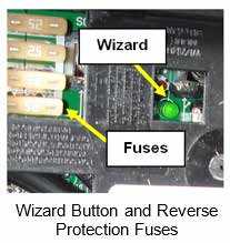
Manual Mode (not recommended): The manual mode button is used to override the charge wizard. Refer to the converter owner’s manual for additional information.
Reverse Battery Protection:
Reverse polarity fuse(s) provide protection for the converter when a battery is used. If the battery is connected back to the fuse board a fuse will blow preventing damage to the converter. Four easily accessible fuses are located next to the wizard button. Replace with fuses of the same type and rating.
12-Volt DC System. The majority of your recreation vehicle lighting is powered by 12-volt electricity. The 12-volt DC system is composed of components that will operate when the following conditions are met:
- Power is supplied by the tow vehicle alternator when the engine is running and the 7-way trailer plug is connected. This powers the RV’s running lights, brake lights, turn signals, and brakes. In addition, the 7-way trailer plug provides a common ground and a 12-volt charge line to charge the auxiliary battery.
- The converter will supply interior 12-volt DC power when the power cord is plugged into campground power. The converter will also charge the RV battery in most situations. (Refer to Battery Disconnect)
- The auxiliary battery powers many interior 12-volt components including the lighting fixtures, water pump, 12-volt motors, 12-volt appliances, etc. It also powers the breakaway switch.
Read all Instructions for Power Converter User Manual
Jayco Eagle Fifth Wheels 2023 Auxiliary Battery User Manual
Auxiliary Battery
- Do not store anything inside the battery compartment(s) or near the batteries that could touch the battery or battery cable terminals. Contact with the battery or battery cable terminals could cause an electrical short circuit, discharge the batteries, or start an electrical fire.
- Keep sparks, cigarettes and flames away from the batteries as the hydrogen gas they create may explode. Do not connect a booster battery or other power source that outputs more than 14.2-volts DC to lead acid or AGM batteries. Use adequate ventilation when charging or using batteries in an enclosed space. Remove metal jewelry and always wear eye protection when working around batteries.
- Do not allow battery electrolyte (acid) to come into contact with skin, eyes, fabric or painted surfaces. Electrolyte is a sulfuric acid solution that could cause serious personal injury or property damage. If your hands, eyes, clothes or the painted surface of your motor home are exposed to electrolyte, flush the exposed area thoroughly with water. If electrolyte gets in your eyes, immediately flush them thoroughly with water and get prompt medical attention.
The combined 12-volt DC loads in your recreation vehicle can become more than the power converter is able to produce. This demand can be met by using an auxiliary battery for a limited period of time. The 12-volt system is designed for usage with a Group 27 or 31, deep cycle battery.
Dry camping
The auxiliary battery should be fully charged prior to dry camping. If the auxiliary battery is not being recharged and power is being drawn from it, it will eventually discharge. Plan your electrical usage accordingly. You can test the auxiliary battery voltage using a volt-ohm meter (customer supplied).
A fully charged lead acid or AGM auxiliary battery will read 12.7 volts DC and 1.265 spe-cific gravity at 80°F (32°C). The auxiliary battery is considered discharged at 10.89 volts, and dead at 10.65 volts. If the voltage drops below those levels, irreversible damage can occur. Typically, a deep cycle battery has an amp-hour rating of 75-100 amps.
If you run the furnace and refrigerator simultaneously, you will be using approximately (12.0 + 3.0) 15.0 amps per hour. This does not include any 12-volt lights, or any other 12-volt component. If the furnace and refrigerator in this example operated constantly, a 75 amp-hour battery would become fully discharged in 5 hours.
The auxiliary battery should be installed in parallel with the battery in your tow vehicle. When the 7-way trailer plug is connected, both batteries power the RV. Do not allow it to discharge your tow vehicle battery below the level required to start the engine. To prevent this from occurring, disconnect the 7-way trailer plug or install a battery isolator. When the tow vehicle engine is operating with the RV connected, the tow vehicle charging system will charge both batteries.
Replacement and maintenance
Some equipment in your RV will draw small amounts of current even when turned OFF. To prevent the auxiliary battery from being discharged when your RV is not connected to shore line power, disconnect the auxiliary battery negative cable at the battery. During storage, it is important to check the voltage monthly and recharge the auxiliary battery as needed. If you remove the auxiliary battery from your RV, store it in a dry, cool area per the manufacturer’s instructions.
When it is time to replace the auxiliary battery, Group 27 or Group 31 true deep cycle batteries are recommended to increase run time of electrical components while dry camping (operating solely on battery power). Do not reverse the positive and negative battery cables (doing so will blow the reverse polar-ity fuse(s) that protect the power converter).
For more information
Please contact the battery manufacturer for additional information on the auxiliary batteries. Battery Isolator For Your Tow Vehicle (customer supplied)
You may want to consider the installation of a battery isolator on your tow vehicle as a convenience feature: It receives current from the tow vehicle alternator and controls the distribution of energy to both the RV auxiliary battery and the tow vehicle battery. It serves as a check valve to prevent energy from being drawn from your tow vehicle chassis battery (so you can start your tow vehicle engine). Your dealer can assist you with the selection, purchase and installation.
DC to DC Power Converter (customer supplied)
If installing lithium batteries in the recreation vehicle, install a DC to DC power converter between the tow vehicle battery charge line and the trailer lithium battery(s) to prevent lithium battery damage.
Battery Disconnect Switch (if so equipped)
The Battery Disconnect switch is typically located in an enclosed exterior compartment. The style of the disconnect switch may vary per model. This switch does not shut off all power, but only shuts off the 12VDC power to the main 12V fuse panel, and the interior of the vehicle. Batteries can still be trickle charged by the converter, and there will still be power to some devices.
Rotating Dial Disconnect Switch
When this switch is ON, there will be a green area showing a “1” along the top of the switch. To turn the switch OFF, turn it counter-clockwise until you see the red area along the left side of the switch showing a “0” (zero).
Lever Type Disconnect Switch
To operate this switch, turn the lever counter-clockwise to turn off all 12VDC power to the fuse panel in the RV. The lever can be removed and is equipped with a lanyard to keep the key from getting lost.
Load Center
The Load Center contains 12VDC fuses and 120VAC circuit breakers for almost all of the electrical appliances and circuits in the RV. The 120V main breaker may be located in this panel and will turn off all 120-volt power to the RV. Load center location, appearance and configuration may vary by model. Refer to the diagram inside the load center for specific fuse assignments. Motor homes may have separate small panels for breakers and fuses. They are normally located in close proximity to each other type in the bed platform. The converter is mounted separately, typically under the bed platform.
120-Volt Circuit Breakers
The 120-volt AC circuit breakers located inside the load center protect all 120-volt wiring and components from circuit overloads and short circuits. Should a circuit overload or short circuit occur the circuit breaker protecting the affected circuit will “trip” preventing the flow of electricity through that circuit.
If a circuit breaker trips, shut off the appliance on that circuit (i.e., power converter, etc.) and allow the circuit breaker to cool down for a brief period of time. After it cools down, reset the circuit breaker by moving its lever “off” and then back to the “on” position. If the circuit breaker re-trips or frequently trips, contact your dealer to have the electrical problem diagnosed and repaired. A circuit breaker identification label is permanently attached to the inside surface of the 120-volt Load Center.
CAUTION
Circuit breakers and fuses will not offer complete protection of the electrical system in the event of a power surge or voltage spike.
Replacement
Only replace circuit breakers with those of the same specified type, voltage, and current rating. Never replace a circuit breaker with one listed at a higher amperage rating. Please contact your dealer for repair assistance when replacing circuit breakers.
WARNING
Replacement circuit breakers must be of the same voltage, amperage rating, and type. Never use a higher-rated replacement circuit breaker; doing so may cause a fire by overheating the RV wiring.
Read all Instructions for Auxiliary Battery User Manual
Jayco Eagle Fifth Wheels 2023 Approximate Electrical Load Ratings User Manual
Jayco Eagle Fifth Wheels 2023 Approximate Electrical Load Ratings User Manual
Approximate Electrical Load Ratings
| 12 VOLT SYSTEM | |
| Exterior Entertainment Center | 5-7 AMPS |
| Fan | 1.5 AMPS |
| Furnace | 12.0 AMPS |
| Generator Start | 95.0 AMPS* |
| Illuminated Switch | .125 AMP |
| Inverter | variable |
| Leveling sSystem | 95.0 AMPS* |
| LP Detector | .125 AMP |
| Light; LED | 1.7 AMPS |
| Light; Vanity | 4.2 AMPS |
| Lights; Aisle | 1.0 AMP |
| Lights; Baggage Compartment / Shower | 1.4 AMPS |
| Lights; Decorative Wall / Map / Porch | 1.5 AMPS |
| Lights; Double -12” | 2.0 AMPS |
| Lights; Double -18” | 2.5 AMPS |
| Power Awning | 10.0 AMPS* |
| Power Vent | 5.0 AMPS |
| Refrigerator | 3.0 AMPS |
| Step Cover | 10.0 AMPS* |
| TV Plate/Antenna Booster | 1.0 AMP |
| Water Heater | 6.0 AMPS |
| Water Pump | 7.0 AMPS |
Momentary Load
| 120 VOLT SYSTEM | |
| Air Conditioner | 18 AMPS |
| Coffee Maker | 6-12 AMPS |
| Converter (each) | 8 AMPS |
| DVD System | 3 AMPS |
| Fireplace | 15 AMPS |
| Hair Dryer or Curling Iron | 10-14 AMPS |
| Microwave | 15 AMPS |
| Refrigerator | 6 AMPS |
| Satellite Receiver | 2 AMPS |
| TV | 2-4 AMPS |
| Vacuum Cleaner | 8 AMPS |
| Washer/Dryer | 12 AMPS |
| Water Heater | 12 AMPS |
120-Volt 30-amp AC Electric System (if so equipped)
The 30-amp 120-volt 60hz AC electrical system is designed to operate on 1 leg of 120-volt power at a maximum current flow of 30-amperes. Exposure to voltages higher or lower than a nominal 120-volts will damage or shorten the service life of the electrical system and appliances. The 30-amp 120-volt 60hz AC electrical system can be powered by the 120-volt 60hz utilities found in campgrounds or by 120-volt 60hz generator power. The following electrical components will only operate when your recreation vehicle is connected to shore or generator power: 120 to 12-volt power converter, air conditioner, refrigerator, microwave oven, television(s), home theater system(s), electric water heater, washer, dryer, fireplace, and appliances plugged into convenience receptacles.
CAUTION
- Make certain the external power source you connect the power cord to is a properly wired 30-amp NEMA TT-30 RV receptacle and not 240-volt AC. PLUG INTO 30-AMP SERVICE ONLY.
- Circuit breakers and fuses will not offer complete protection of the electrical system in the event of power surge or voltage spike.
30-amp Power Cord
WARNING
- Do not hook up the power cord to any receptacle until you have verified proper polarity and grounding. Polarity indicators can be purchased in most electrical and hardware stores.
- Do not use any cheater plug, adapter or extension cord to reconfigure incoming AC power or break the continuity of the circuit connected to the grounding pin.
- Do not connect the power cord to an outlet that is not grounded, or adapt the power cord plug to connect it to a receptacle for which it is not designed.
- Do not remove the grounding pin to connect to a non-grounded receptacle. Removal of the ground pin disables an important safety feature designed to prevent shock and electrocution hazards.
- Do not connect the power cord to an extension cord. Use of an improper extension cord will cause overheating of the cord as well as potentially cause premature failure of the AC equipment.
Read all Instructions for Approximate Electrical Load Ratings User Manual
Jayco Eagle Fifth Wheels 2023 Solar Package User Manual
Solar Package
CAUTION
If expanding upon OEM installed solar package, ensure all components are compatible with an existing product. Any additional equipment will reduce Car-go Carrying Capacity (CCC) when installed. Your recreational vehicle may be equipped with a factory-installed solar panel kit that includes lithium batteries, a DC/DC power converter (allows charging from the tow vehicle connection.), Solar Panels, and an energy management control system. For care and operation, please refer to the manufacturer’s instructions provided with your RV. Never connect your tow vehicle harness to a recreation vehicle equipped with a lithium battery without a DC/DC power converter installed. Direct tow vehicle charging may cause permanent damage to the lithium battery unless the vehicle charge line is properly voltage regulated or disconnected.
Adding solar panels or equipment will affect the carrying capacity of your recreation vehicle. Vehicle weight ratings should be considered before adding these components. Your recreation vehicle may be wired with a (exterior) plug-in that will allow the batteries to be trickle charged using a free-standing solar panel. In most models, the solar panel kit is a customer-purchased and installed option. The solar plug location will vary by model, but may be located on the exterior sidewall, on the A-frame of the RV, in the outside utility center, or mounted up on the roof. There are capped-off wires located in the area of the battery. These wires are the battery charging wires. Once these wires are properly connected to your battery, you will then be able to plug the solar panel into the charging port.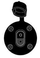
Solar System
When the system is connected properly, the solar panel will supply power to the battery, the battery will supply power to the converter, and the converter will supply power to all the 12V systems as needed.
Replacing Lighting
Replacement lighting must be the same type, voltage, and wattage listed on the lamp fixture. Use of incorrectly sized replacements can overload lamp circuits and may create a fire hazard by overheating the fixture.
Exhaust Gas Fumes
WARNING
- Avoid inhaling exhaust gases as they contain carbon monoxide, which is a potentially toxic gas that is colorless and odorless.
- If you are in a recreation vehicle with either a nearby tow vehicle engine running or the generator (if so equipped) running there is a potential for exhaust fumes to filter back into the recreation vehicle.
To avoid breathing exhaust gases, follow these precautions:
- Always shut OFF the tow vehicle engine, generator engine (if applicable), etc., while refueling.
- Do not run the tow vehicle engine, generator engine (if applicable), etc., in confined areas, such as a closed garage, any longer than needed to move your RV in or out of the area.
- Windows should be closed while driving or running the generator (if so equipped) to avoid drawing dangerous exhaust gases into the RV.
- If you suspect that exhaust fumes are entering the RV have the cause determined and corrected as soon as possible.
The best protection against carbon monoxide entry into the RV is a properly maintained ventilation system and an active carbon monoxide detector. To allow for proper operation of the RV ventilation system, keep the ventilation inlet grill(s) clear of snow, leaves, or other obstructions at all times.
See the Occupant Safety section of this manual for additional information on carbon monoxide safety.
Propane Gas System
Propane or LP (liquefied petroleum) gas is an efficient form of energy when proper handling and safety precautions are observed. The propane system in your furnishes the fuel for cooking, heating, and hot water and can be an alternative energy source for refrigeration. Propane is heavier than air; and tends to flow to lower areas and will sometimes pocket in these low areas, such as the floor. Your recreation vehicle is equipped with a propane alarm (refer to the Safety Precaution section, Combination Carbon Monoxide (CO)/Propane Alarm).
WARNING
Propane cylinders should not be placed or stored inside RV. LP-gas cylinders are equipped with safety devices that relieve pressure by discharging gas into the atmosphere.
The propane fuel system is comprised of numerous components such as the propane container, hoses, the propane gas regulator, piping and copper tubing to each appliance. Although your recreation vehicle has been carefully tested at the factory, and by your selling dealer for leakage, travel vibrations can loosen fittings. Have the propane system checked at all connections soon after the purchase of your recreation vehicle, and after the initial filling of the propane tanks. Continued periodic checks of the propane system at 5,000 miles of travel (or at least once a year), by a qualified propane service representative as part of your normal maintenance is recommended. Hand-tighten the LP gas system valves only, do not use a wrench or pliers as over-tightening may damage the valve seals and cause them to leak.
NOTE:
All propane lines have been checked with air pressure at the time of manufacture. Dealers are required to recheck and adjust pressure before retail delivery.
Read all Instructions for Solar Package User Manual
Jayco Eagle Fifth Wheels 2023 Fuel and Propane System User Manual
Jayco Eagle Fifth Wheels 2023 Fuel and Propane System User Manual
Fuel and Propane System
Warning
- DOT propane cylinders must be transported and stored in an upright position so the pressure relief device will function properly. Laying a DOT propane cylinder on its side may potentially create a very dangerous situation.
- The pigtail hose must be installed to avoid tension or pulling stress at either end of the hose. Keep the pigtail hose away from sharp edges of the cylinder collar, rigid corners, walls, doors or other compartment structures including the cover.
- Before entering a propane or fuel service station make sure all pilot lights are extinguished. Shut off the gas to all appliances by closing the propane gas main shut-off valve. Always shut OFF any engine before refueling. Do not smoke and do not operate other ignition sources while refueling.
- If you suspect your propane container has been overfilled, contact your dealer or a qualified propane technician for assistance immediately. Do not attempt to service a propane container overfill yourself.
Propane “container” is a general all-inclusive term used to describe a vessel that is used for storage and delivery of propane gas.
The most common of these are:
DOT (Department of Transportation) cylinders are transportable and are commonly used on recreation vehicles. The capacity of DOT propane cylinders is expressed in pounds. DOT propane cylinders are required to be removed from the RV for filling and must be filled by weight by a qualified propane facility. DOT Propane cylinders are equipped with an OPD (over fill protection device) designed to reduce the potential of overfilling. DOT propane cylinders are also equipped with an ACME service valve that is for connection of the TYPE 1 ACME pigtail hose assembly to the RV two-stage regulator.
The TYPE 1 ACME pigtail hose assembly is a wrench less, right hand threaded connector that features a thermally sensitive sleeve and excess flow device. Max output is 200,000 BTU/hr. It is used to connect propane cylinders to regulators, hoses and other fittings. It is not for use on gas grills and other low pressure devices. DOT cylinders equipped with an OPD and ACME type 1 service valve are identified by the triangular service valve knob.
DOT cylinders are typically marked with “top” or an arrow to indicate the correct orientation of the cylinder(s). Do not mount, store or transport any cylinder other than the in proper position indicated. Be sure to securely re-install DOT cylinder(s) after they have been removed for filling or replacement. Always close the service valve and install a dust cap or plug when transporting or storing disconnected containers whether full or empty.
ASME tanks are permanently mounted to the RV and are commonly used on RV motorhomes. The capacity of ASME tanks is expressed in gallons. ASME tanks are filled while the tank is attached to the motorhome by a qualified propane facility. ASME tanks are equipped with an automatic stop fill valve designed to reduce the potential of overfilling. ASME propane tanks are also equipped with a P.O.L. service valve that is for connection of the supply hose with a left hand threaded brass P.O.L. fitting from the tank service valve to the two-stage regulator. Not for use on gas grills and other low pressure devices.
NOTE:
Tanks are to be installed, fueled and maintained in accordance to State and Local codes, rules, regulations or laws.
Propane is a true gas compressed into a liquid form. As the fuel is released from the container, it changes to vapor which is then used for the operation of the appliances. Propane will not run through the appliances in a liquid state. Propane expands 1½ percent for every ten degrees of increase in temperature. It is imperative to leave sufficient space inside the container to allow for the natural expansion of gas during warmer weather.
The main shut-off valve must be kept closed at all times unless you are using the propane system or filling the propane cylinder. When the cylinder is disconnected from the hose, install the valve cover that is attached to the container. Close the propane cylinder main shut-off valve by hand tightening only. Use of tools create to over-tighten the valve (damaging the interior seals on the cylinder valve seat). If this type of damage occurs, the cylinder will not close properly.
This propane label should be kept permanently affixed to your RV. “Use propane only” Label.
Read all Instructions for Fuel and Propane System User Manual
Jayco Eagle Fifth Wheels 2023 Servicing or Filling User Manual
Jayco Eagle Fifth Wheels 2023 Servicing or Filling User Manual
Servicing or Filling
Have the recreation vehicle checked for leaks at the connections on the propane system soon after the purchase and the initial filling of each propane cylinder.
When you have a new cylinder filled for the first time, make sure your propane supplier purges your new cylinder of trapped air. Otherwise, an
an improper mixture of gas and air will make it impossible to light your propane appliances.
No one should be inside the RV and only the qualified propane service technician should be near the RV while the propane tank is being filled. The new propane container must be carefully purged for best performance and must NEVER BE OVERFILLED. This “shut off for re-fueling” label should be kept permanently affixed to your RV.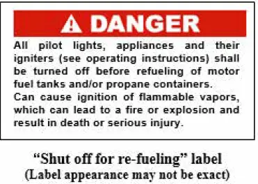
The position of the propane container(s) and the hoses are critical to proper operation and propane flow. Follow these instructions to make sure your propane container(s) are connected properly.
LP Gas Container Overfil
Never allow your propane tank to be filled above the maximum safe level as indicated by the fixed liquid level gauge. Do not allow the visible gauge to be used for filling. Overfilling the propane container above the liquid capacity indicated on the container could allow liquid propane to enter the system that is designed for vapor only creating a hazardous condition. The propane piping system is designed for use with propane only. Do not connect natural gas to this system. This label should be kept permanently affixed to your RV. Refer to your Warranty Packet for more information on the LP gas system components.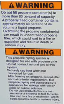
Maintenance
Propane gas is normally non-corrosive – you need not worry about the inside of your container. However, the outside should be kept free from rust by a periodic coat of paint in a light reflective color. Rust, scratches and/or dents can affect the safety of the cylinder. Inspect the cylinder at regular intervals.
Ifs a problem, have it evaluated by a qualified technician and discard it. DOT requires that a visual inspection be made prior to each filling.
Any cylinder that has been exposed to fire, leaks or seems dam-aged should not be refilled. Do not attempt to repair any containers, container valves, regulator or appliances by yourself. Use only trained certified pro-pane gas service technicians to perform repairs.
DOT cylinders may only be used for 12 years after their manufacture date (the number of years for certification may vary in your area). After that, the cylinders must be “recertified” which provides another five years of use. The cylinders can be recertified every five years thereafter. Federal DOT (Department of Transportation) regulations require periodic inspections and re-qualifications of the propane cylinders. DO NOT USE damaged or rusted containers.
Verify with your local propane dealer that all required inspections and certifications have been completed on the propane cylinder within the correct time period before refilling the cylinder. Have the LP system checked for leakage each time a cylinder is refilled or after any part of the propane system has been disconnected.
Hoses, Pipes, Tubes and Fittings
The hoses, pipes, tubes and fittings used in your propane system are designed to withstand pressures exceeding those of the propane system. However, because environment and time can both contribute to the deterioration of these components, they must be inspected for wear at regular intervals.
Be sure to inspect the hose before each season and when having the tank refilled. Look for signs of deterioration such as cracks or loss of flexibility. When replacing the hose or other propane components, make sure to always replace them with components of the same type and rating (check with your dealer).
Fittings are used to connect the various system components to each other. The P.O.L. fitting at the end of the propane supply hose is made of brass so pipe sealants are not necessary to prevent leaking. It also has a left-handed thread, which means that it is turned clockwise to remove, and counter-clockwise to tighten. The P.O.L. fitting has been designed to help restrict the flow of LP gas in the event of a regulator failure or hose malfunction.
Read all Instructions for Servicing or Filling User Manual
Jayco Eagle Fifth Wheels 2023 Propane Regulator User Manual
Propane Regulator
Warning
Propane regulators must always be installed with the regulator vent facing downward. Regulators that are not located in baggage compartments have been equipped with a protective cover. Make sure the regulator vent faces downward and (if applicable) the cover is in place to minimize vent blockage that could result in excessive gas pressure causing fire or explosion.
Single stage regulator
Some models are equipped with a single-stage regulator.
Two-stage regulator
The two-stage regulator has the only moving components in the propane system. Its sole function is to reduce the pressure from the propane containers to a safe and consistent low operating pressure. The first stage reduces the container pressure to 10-13 lbs. The second stage reduces the 10-13 lbs. of pressure further to an operating pressure of 11” W.C. (water column) or 6.35 oz. of outlet pressure to your appliances. The second stage is adjustable and will need to be adjusted by your dealer or qualified pro-pane service technician for optimum performance (this adjustment should always be made with a properly calibrated manometer).
If the pressure is too high, it affects performance and safety; if the pressure is too low, your appliances will not operate correctly.
If your recreation vehicle is equipped with the “automatic” two-stage regulator, with both cylinders full of propane, turn the lever on the regulator towards the cylinder you wish to use first. This will now be the “supply” cylinder and the other the “reserve”. Slowly open both cylinder valves. The indicator on top of the regulator will turn bright green. When the cylinder becomes empty, the indicator will change to bright orange. Now turn the regulatory lever to the side of the “reserve” cylinder and the green signal should return. You may now remove the empty cylinder to have it refilled without interrupting the flow from the full bottle. After filling the cylinder, connect the pigtail hose and slowly open the bottle valve. Refer to the manufacturer’s information included in your warranty packet and follow all safety instructions and warnings listed.
Propane Use and Safety
Propane is a colorless and odorless gas that, in its liquefied state, resembles water. An odorant (usually a sulfur compound) is added as a warning agent. If you smell propane within the vehicle, quickly and carefully perform the procedure listed on the propane system label. This label has been placed in the vehicle near the range for models equipped with a propane system. When a propane container is low, there may be a concentration of an onion or garlic-like odor, which can be mistaken for a propane gas leak. After the propane container has been refueled, the odor will usually disappear. If not, turn off the valve(s) and have the propane system inspected by your dealer or qualified propane service representative.
Propane Leak Test
Leaks may be found easily with a soapy water solution. Do not use a solution containing ammonia or chlorine when locating leaks. These products are corrosive to copper gas lines and brass fittings, which could result in the deterioration of the copper and brass components. Apply the soapy solution to the outside of the gas piping fittings. If a leak is present, the soapy solution will “bubble” at the leak point. If a leak is indicated, shut off the propane system valve(s) and contact your dealer or qualified propane service representative immediately.
Danger
Never use an open flame to test for a propane leak. Do not check for leaks using products that contain ammonia or chlorine; these products can cause cracks to form on the metal tubing and brass fittings.
When the cylinder becomes empty, the indicator will change to bright orange. Now turn the regulatory lever to the side of the “reserve” cylinder and the green signal should return. You may now remove the empty cylinder to have it refilled without interrupting the flow from the full bottle. After filling the cylinder, connect the pigtail hose and slowly open the bottle valve. Refer to the manufacturer’s information included in your warranty packet and follow all safety instructions and warnings listed.
Read all Instructions for Propane Regulator User Manual
Jayco Eagle Fifth Wheels 2023 Using Propane System User Manual
Jayco Eagle Fifth Wheels 2023 Using Propane System User Manual
Using the Propane System
Use the following steps for propane operation:
- Close ALL burner valves, controls and pilot light valves.
- Open the main valve in the propane tank slowly to avoid a rush of propane vapor through the excess flow valve, causing propane “freeze-up.” Should you experience propane “freeze-up”, close the main valve and wait 15 minutes before trying again.
- Listen carefully as propane begins to flow. If a hissing noise is heard for more than one or two seconds, close the main valve and contact your dealer to have the propane system tested.
- Light the appliances as needed and directed in the appliance manufacturer’s owner manual located in the Warranty Packet.
Keep the propane container valves closed at all times unless you are using the propane gas system or are having the propane container filled.
Make sure that you read and fully understand ALL safety requirements for handling and operation of the propane system.
The propane system must be handled with care. If you have any questions or concerns, consult with your dealer and/or the specific appliance manufacturer.
If you have double cylinders on your recreation vehicle, use only one at a time. Otherwise, the propane supply will be drawn equally from both cylinders until the supply has been to-tally exhausted. Using one cylinder until it is empty and then using the second cylinder will allow you to fill the empty cylinder at your convenience without running out of propane.
Cooking With Propane Gas
Warning
- Do not turn gas range burner controls to ON and allow gas to escape before lighting.
- Do not use portable fuel-burning equipment (i.e., wood and charcoal grills or stoves) inside the recreation vehicle.
Unlike homes, the amount of oxygen supply is limited due to the size of the recreation vehicle. Proper ventilation when using the cooking appliance(s) will help avoid the danger of asphyxiation. It is especially important that cooking appliances not be used for comfort heating, as the danger of asphyxiation is greater when the appliance is used for long periods of time.
FAILURE TO COMPLY MAY RESULT IN DEATH OR SERIOUS INJURY.
These warning labels are located in the cooking area to remind the user to provide an adequate supply of fresh air for combustion.
Calculating Propane Gas Usage
Most RV gas appliances are operated intermittently, and each has a different BTU rating. You will need to consider this when planning your propane supply and consumption. Unless there is heavy use of hot water, the water heater consumption of propane is minimal. During cool temperatures or high wind conditions, furnace consumption can be extremely high. To calculate your propane supply, take the BTU ratings for your propane appliances and divide that into the BTU availability. Each gallon of propane gas (3.785 liters) produces about 91,500 BTUs (96,528 kilojoules) of heat energy.
Propane consumption chart
The following chart provides average propane consumption information.
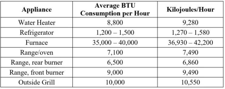
Traveling With Propane
NOTE:
Some states prohibit propane appliance operation during travel, especially in underground tunnels. Know the laws for the areas where you travel.
Danger
All pilot lights, appliances and their igniters (see operating instructions) should be turned off before refueling of motor fuel tanks and/or propane containers.
These can cause ignition of flammable vapors, which can lead to a fire or explosion.
FAILURE TO COMPLY COULD RESULT IN FIRE, DEATH OR SERI-OUS INJURY.
Use care when fueling your motor fuel tanks and/or propane containers. Make certain your propane tank is properly fastened in place.
Installing Propane Cylinder(s)
Single Cylinder Mounted On A-Frame (if so equipped)
- Connect the 3/8” low pressure hose to the outlet of the two stage regulator.
- Attach the regulator with the “Z” bracket on the center of the front wall with the vent pointing down.
- Attach the protective plastic cover to the regulator.
- The regulator has a 90° elbow that directs the inlet toward the trailer curbside.
- Place the cylinder on the bracket provided on the
- frame and position it so the outlet of the cylinder valve is pointed directly outward to the curbside wall.
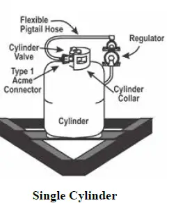 Attach the 1/4” inverted flare x 24” Type 1 pigtail hose to the regulator inlet and the right-hand swivel nut to the cylinder valve.
 - Secure the cylinder to the A-frame bracket using the bolts, nuts, and washers provided.
Read all Instructions for Using Propane System User Manual
Jayco Eagle Fifth Wheels 2023 Double Cylinder Mounted On A-Frame User Manual
Jayco Eagle Fifth Wheels 2023 Double Cylinder Mounted On A-Frame User Manual
Double Cylinder Mounted On A-Frame
When a second cylinder is installed, a tee check valve is used to replace the 90° elbow at the top of the regulator and another 1/4” inverted flare x 24” Type 1 pig-tail is added. The regulator stays in its original position. Place the second cylinder on the A-frame bracket so the cylinder valve is pointed to the roadside of the recreation vehicle.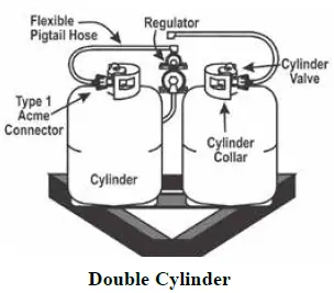
- Secure the second cylinder to the A-frame using the bolts, nuts and washers provided.
- Attach the second 24” hose to the tee check valve on the regulator and the right-handed swivel nut to the cylinder valve.
Located in a recessed compartment or housing (if so equipped)
- Connect the 3/8” low-pressure hose to the outlet of the two-stage regulator.
- Place the cylinder on the bracket in the recess compartment or housing and secure them so the outlets of the cylinder valves are facing the “sidewalls” of the compartment or housing (opposite of each other).
- Mount th4. Attach the 1/4” inverted flare x 18” Type-1 pigtail hose regulator on the center back wall of the compartment or housing so the vent is pointed downward. to the regulator inlet and the right hand swivel nut to the cylinder valve.
- Attach the 1/4” inverted flare x 18” Type-1 pigtail hose to the regulator inlet and the right hand swivel nut to the cylinder valve.
Main Supply Hose – Low Pressure
Attach the main supply hose from the regulator to the brass manifold fitting in the frame of the trailer. The swivel brass nut on the main hose will be your final attachment.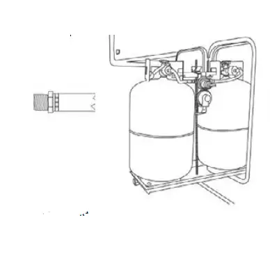 Each time the propane container is removed:
- Check that ALL fittings are tight.
- Check that ALL connections are tested with a propane leak detector (or soapy water) solution.
- Open the main valve slowly to avoid a fast rush of propane to the excess flow valve causing propane freeze up. If you experience a propane “freeze-up,” close the main valve and wait at least fifteen (15) minutes before trying again. Refer to the regulator manufacturer’s operator manual.
- Listen carefully – a “hissing” sound longer than one second may indicate a propane leak. If you feel there may be a leak present, close the valve and contact your dealer or qualified propane technician for repair assistance.
Replace all protective covers and caps on the propane system after filling. Make sure the valve is closed and the compartment door is securely latched.
Plumbing System
There are two different water systems in your recreation vehicle:
- The freshwater system consists of the freshwater holding tank, faucets and connections, water pump, water heater, tub/shower. On some models, it may also include the water purification system or outside shower assembly (if so equipped).
- Depending on your model, the wastewater system consists of the wastewater and sewage holding tank(s), drains and toilet. Models with a cassette toilet will only have the wastewater system.
Plumbing System Maintenance
- Check all fittings, pressure and waste, for leaks before each trip or before vehicle storage as part of your normal maintenance:
- Inspect all faucets, the water purification system (if so equipped), and sink connections (including drain baskets or filters).
- Inspect connections at the water pump and water heater (if so equipped).
- At the end of every trip, you should drain any unused water from the freshwater system.
Typically, there are labels affixed to the exterior of the recreation vehicle sidewall that indicate the locations of the water system drains and fills. Be aware some drain valves may be located inside the vehicle (once the exterior label is found, go inside to find the drain corresponding location).
Refer to the manufacturer’s operating manual included in your warranty packet for the detailed operating, sanitizing, and winterizing information for each water system component.
When a second cylinder is installed, a tee check valve is used to replace the 90° elbow at the top of the regulator and another 1/4” inverted flare x 24” Type 1 pig-tail is added. The regulator stays in its original position. Place the second cylinder on the A-frame bracket so the cylinder valve is pointed to the roadside of the recreation vehicle. Attach the main supply hose from the regulator to the brass manifold fitting in the frame of the trailer. The swivel brass nut on the main hose will be your final attachment.
Read all Instructions for Double Cylinder Mounted On A-Frame User Manual
Jayco Eagle Fifth Wheels 2023 Monitor Panel User Manual
Monitor Panel
Monitor panel locations may vary by model. Typical locations are on the command center panel, on an interior wall, or on the exterior utility center. Some models may be equipped with a touchscreen system that monitors tank levels electronically. The monitor panel allows you to monitor the fresh water, grey water, black water and auxiliary battery levels. These functions are controlled using the tact switches. It operates on 12-volt DC power supplied by either the converter or auxiliary battery. No power is drawn from the battery unless a switch is pushed or turned ON. Fuses for the monitor panel are located in the load center. Refer to the manufacturer’s operator’s manual for additional information.
NOTE:
If your RV has secondary black or gray tanks, there may be an additional tank monitor. It is typically labeled as a convenience center.
Operation
Press only one tact switch at a time. As you push either the FRESH, BLK GREY1, or GREY2 switch, one or more LED lights will illuminate (from left to right) indicating the content level for that tank. When pushing the “BATT” switch, the LED lights illuminate from left (lowest) to right (highest) to indicate the estimated auxiliary battery condition.
NOTE:
When using shore power all (4) LEDs will light. If disconnected from shore power, (3) LEDs will light to indicate a full charge (4th LED may blink).
The LEDs on the panel indicate the following:
C= Charge at 12.7 volts
G = Good at 12.1 volts
F = Fair at 11.6 volts
L = Low at 6.0 volts
Tank monitors on the touch screen have a constant readout. There are no buttons to push. Tank levels are displayed by percentage from 0% to FULL.
Level Alert Button (if so equipped): some models may be equipped with a Level Alert Button. When this LED flashes a tank requires attention. To silence the alarm press the level alert button.
Water pump switch (if so equipped)
This switch may be located on the monitor panel, the utility center, or both. On some models, the water pump control may be on one of the selectable screens for the touch screen. When the water pump switch is ON (lit), the water pump will run until it reaches 45 lbs. of pressure. It will recycle when pressure drops. Turn the switch OFF when the water pump is not being used.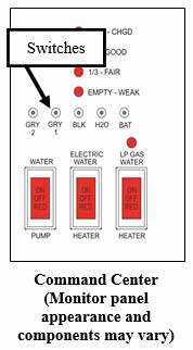
Water heater switch(s) (if so equipped)
These switches can be located on the monitor panel, the command center, or in the case of a touch screen system, on one of the selectable screens of the touch screen. Switches will light up when turned on. The “LP GAS” water heater switch (12V) enables the propane operation of the water heater, and the “ELECTRIC switch (120V) enables the electric operation of the water heater. Normally both switches should be turned on to provide the fastest hot water recovery time. The water heater can be operated in electric-only or gas-only modes by pressing each switch independently. If the RV is equipped with a tankless water heater, there will be only an LP Gas switch on the command center panel.
DSI FLT – Direct Spark Ignition Fault (if so equipped)
This light located between the water heater switches will indicate a problem with the LP portion of the water heater. When the LP GAS switch is turned on, the light will blink quickly 3 times and the water heater will ignite. The light will then remain off. If the light comes on and stays on, it indicates the gas side of the water heater has not fired and there is a problem with the igniter.
NOTE: This light will not appear on touchscreens, RV remote controls or on a Wi-Fi app, only on the Command Center switch panel.
Press only one tact switch at a time. As you push either the FRESH, BLK GREY1, or GREY2 switch, one or more LED lights will illuminate (from left to right) indicating the content level for that tank. When pushing the “BATT” switch, the LED lights illuminate from left (lowest) to right (highest) to indicate the estimated auxiliary battery condition. Tank monitors on the touch screen have a constant readout. There are no buttons to push. Tank levels are displayed by percentage from 0% to FULL.
Read all Instructions for Monitor Panel User Manual
Jayco Eagle Fifth Wheels 2023 Fresh Water System User Manual
Fresh Water System
All water contains contaminant and mineral particles that can cause fresh water system odors. Untreated well water is a major source of water system odors. The fresh water (potable water) system needs periodic sanitization to take care of all the components in the plumbing system to discourage the growth of bacteria and other organisms that can contaminate the water supply.
WARNING
- DO NOT drink water deemed microbiologically unsafe or of unknown quality.
- Avoid traveling with full fresh, black or grey water holding tanks. The weight of holding tank contents in not calculated into the RV cargo car-trying capacity. Traveling with full tanks could cause you to exceed the individual tire ratings and/or the RV GAWR or GVWR. Traveling with full tanks can also affect your vehicle handling characteristics.
Do not remove the potable water label from your recreation vehicle. You should use a non-toxic drinking water hose dedicated only to supplying the recreation vehicle with fresh water. To reduce the chance of contamination, prevent the non-toxic drinking water hose from coming into contact with the ground.
NOTE: If needed, sanitize the water system prior to travel.
Water Pressure Regulator (customer supplied)
CAUTION
A water pressure regulator is recommended to prevent damage to the plumbing system or components. To prevent damage when using the city water connection, a 45 lb. (315 KPa) rated water pressure regulator is recommended. Excessive pressure from the water supply source may be encountered in some parks, especially in mountain regions when using the freshwater inlet or black tank flush. Water pressure regulators are available to protect your recreational vehicle’s plumbing system against such high pressure.
Fresh Water Holding Tank
- Do not cap, block or modify the fresh water tank overflow tubes in any way. Enough water pressure can build up during the filling process to damage the plumbing system if the overflow tubes are obstructed.
- Be careful not to overfill the freshwater holding tank. It can pressurize the tank, causing leakage and water damage and void the warranty. DO NOT leave the tank unattended while filling.
There may be several ways to fill the freshwater tank depending on the model. For details of each method, refer to the Utility Center or Water Connection section. There are plastic overflow tubes in the freshwater holding tank which allow water to flow out of the water tank. Occasionally, you may see water coming from the overflow tubes when the freshwater holding tank is filled. This is normal and can be a result of the recreation vehicle being parked on an incline, or the motion caused by starting or stopping during travel.
12-volt Water Pump
There must be sufficient 12-volt DC power to run the water pump when your recreation vehicle is not hooked up to city water. Once activated, the water pump (also known as the demand pump) will self-prime, and provide water. The water pump continues to run until maximum pressure is achieved and shut off. The water pump will automatically restart when it senses a drop in the water pressure. The pump is designed for intermittent use only. Using the pump continuously or with high pressure will shorten the life of the pump and is not covered in your warranty. Some cycling may occur, depending on the volume of water being released. The water pump is engineered with a check valve to prevent water from back flowing into the freshwater supply tank.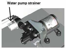
NOTE: The water pump switches should be in the OFF position when the recreation vehicle is left unattended for any amount of time.
Maintenance
Periodically check the in-line water pump strainer for accumulated debris. To clean, shut off the water pump, unscrew the clear cap, remove the re-useable metal strainer, clear any debris, then reinstall. Normal pump maintenance consists of checking and cleaning of the strainer, normal sanitizing and winterizing and occasionally checking all plumbing hardware and fittings for tightness. Lack of sanitizing can lead to premature pump failure and poor performance over time. Scale build-up on the diaphragm and valves, can cause low flow and leak back (occasional pump cycling with no faucets open or tank filling up when hooked up to city water). For additional information on the care and operation of the pump, read the safety and operating information in the pump manufacturer’s owner’s manual.
Water Pump Switch
Most water pump switches illuminate when the water pump is activated. Typical switch locations are in the back of the unit or on the monitor panel, or the switch may be art of a touchscreen system (if so equipped). When the water pump switch is ON the pump runs until 45 lbs. of pressure has been achieved. The red light will stay on.
Draining The Fresh Water System
Water tanks may be drained through a valve located near the tank. A recreational vehicle with a demand pressure pump system will have low-point drains attached to the water lines (normally located near the water tank). These low-point drains will release water in the supply lines by opening the valves and all faucets. The water heater has its own drain plug.
To drain the permanent fresh water holding tank and supply lines:
- Turn the water heater power OFF (turn off the electric and LP gas switches).
- Open all faucets, including the outside shower faucet (if so equipped).
- Open the “fresh tank drain” valve. Methods to drain the freshwater tank may vary by model. Fresh water tanks can be drained by one of the following methods:
- A white plastic drain is attached to the exterior wall.
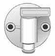
Exterior Fresh Water Drain
- A valve located inside the RV adjacent to the water tank (turn 45° to open or close).
- Pull the white “T” handle on the fresh water holding tank to drain the water.
- Low point drains are installed at the lowest point of the water lines. A label is placed on the outside of the RV to indicate where
the drains are located. The type of drain may vary by model. You will have either an interior or exterior drain. - Interior drains: the drains will need to be operated from inside the RV. Once the label is found on the exterior sidewall, the drains will be found at a corresponding location in the interior.
- Exterior drains: Open the “low point drains” by removing the black screw-on caps on the water lines (coming out from the underbelly). The drains will typically need to be opened from outside the RV.
Read all Instructions for Fresh Water System User Manual
Jayco Eagle Fifth Wheels 2023 Water Heater Bypass User Manual
Water Heater Bypass
The water heater bypass valve is typically located in the utility center compartment. It allows you to bypass the water heater when winterizing or sanitizing to avoid damage to the water heater. The valve has (2) positions NORMAL and BYPASS.
City Water Connection Inlet
Use a non-toxic drinking water hose dedicated only to supplying fresh water. To prevent contamination, keep the non-toxic drinking water hose from coming into contact with the ground. Install the city water connection inlet cap when the fresh water connection is not being used. The fresh water connection should be disconnected (i.e., the non-toxic drinking hose disconnected) when the recreation vehicle is unattended for any amount of time. If something would happen to the water system, this may help limit water damage to a smaller area.
WARNING
A check valve is located inside the city water connection inlet on the utility center. NEVER depress the check valve on the “CITY WATER CON-NECTION” inlet with pressure in the line. It will cause irreparable damage to the valve function and the inlet will leak water.
2-Valve Position and Routing Information:
Green Handle: Receives water from Sanitize/Winterize inlet on front panel. Sideways: Water goes from the inlet to the pump.
Down: Water goes to the freshwater tank.
Blue Handle: Receives water from the City Water Connection inlet on front panel. Sideways: Water goes to fixtures in the RV (cold).
Down: Water goes to or from the freshwater tank.
City Water (Pressurized fresh water source)
- Connect the fresh water hose to the city water inlet.
- Set the color coded valves to the CITY WATER setting:
- Green handle pointing left
- Blue handle pointing right
- Water heater bypass lever – NORMAL.
- Connect other end of the hose to the pressurized fresh water source.
- Turn ON the pressurized water source.
- Water should now be available to all fixtures in the RV.
To disconnect from city water, turn off water at the pressurized source first. Disconnect the hose from the water source, (to release pressure off the system) then disconnect the hose at the city water connection on utility center last.
Filling the Fresh Water Tank (Pressurized fresh water source)
- Connect the fresh water hose to the CITY WATER inlet on the utility center.
- Turn handles to TANK FILL position.
- Green handle pointing left
- Blue handle pointing down
- Water heater bypass lever – NORMAL
- Connect the other end of the hose to a pressurized fresh water source (faucet or spigot).
- Turn the pressurized water source ON, the tank should begin filling.
- When water has reached the desired level, turn the pressurized water source OFF. DO NOT OVERFILL (tank level can be viewed on the monitor panel inside the RV).
- Disconnect water source from the spigot/faucet first, then disconnect from the city water fill inlet on the utility center.
Dry Camping (pump supplies water from the freshwater tank)
- Make sure the freshwater tank has an adequate supply of water.
- Set the color-coded valves to the DRY CAMPING setting:
- Green handle pointing down
- Blue handle pointing right
- Water heater bypass lever – NORMAL
- Turn the pump switch ON. The LED indicator light below the pump switch will be lit if the pump has power.
- Water should be available to all fixtures. Pump runs when a fixture is opened.
- Turn pump OFF when water is not being used.
- NOTE: To fill the fresh water tank without a pressurized water source, refer
to SANITIZE (Siphon Fill) section, and use a container holding fresh po-table water and your fresh water hose. Water will be drawn into the tank by the pump. There is no gravity fill inlet on the recreation vehicle.
Sanitizing the Plumbing System (with a storage tank water heater) When to sanitize
- When your RV is new.
- At the beginning and end of each season.
- When the water system becomes contaminated or every three months of use.
Preparing to Sanitize
Prepare a chlorine solution using 1/4 cup of household bleach (sodium hypochlorite solution) to one gallon (3.785 liters) of water in a container. Prepare one gallon of solution for every 15 gallons of tank capacity. This will result in a residual chlorine concentration of 50 ppm in the water system.
If a 100-ppm concentration is required, use ½ cup of household bleach with one gallon of water to prepare the chlorine solution. One gallon of the solution should be used for each 15 gallon of tank capacity.
NOTE: Fresh water tank sizes vary by model. Contact your dealer or Customer Service for your specific tank size.
How to Sanitize
- Turn water heater power OFF (both electric and LP gas on standard storage water heater). Set the colored valves to SANITIZE/WINTERIZE setting:
- Green valve pointing left
- Blue valve pointing down
- Set the red water heater bypass lever (located in the utility center compartment) to BYPASS. Red lever will be pointing up.
- Level the recreation vehicle and drain the fresh water system (see Draining the Fresh Water System). Do not drain the water heater or remove the water heater drain plug.
- Close the low point drain valves and the fresh water tank drain valve.
- Remove and bypass the water filter:
- Full System Canister water filter (if so equipped):
Turn water valves off at the canister. Remove the canister lid, take the filter out of the canister, then replace the lid and turn the water valves back on. - Bypass the cartridge water filter (if so equipped):
Use the clear plastic tube (supplied with RV) to bypass the water filter. - NOTE:
Filters should be replaced at the beginning of the camping season or if they have been exposed to contaminated water, sanitizer or antifreeze.
- Full System Canister water filter (if so equipped):
- Attach a short section of garden hose to the SANITIZE/WINTERIZE inlet at the utility center. DO NOT use your fresh water hose for sanitizing.
- Insert the other end of the short hose into a container holding the chlorine solution.
- Turn the pump switch ON (red LED will light). The solution will be drawn into the fresh water tank. Turn the pump OFF when solution has been drawn into the tank. To aid in siphoning, set the container on a surface approximately (2) feet off the ground. The drain valves must be turned OFF.
- Disconnect the short hose from the SANITIZE inlet. Leave the colored valves in the SANITIZE position.
- Power Fill Water Tank Attach your fresh water hose to the CITY WATER inlet at the utility center. Connect the other end of the hose to a pressurized water source. Turn the water on and finish filling the water tank with fresh water. DO NOT OVERFILL THE TANK! Use the LED indicators on the tank monitor inside the RV at the Command Center panel to monitor water level in fresh water tank. Siphon Fill Water Tank If there is no pressurized water source available, fresh water can be siphoned into the water tank from an external container (bucket). Fresh water hose should be connected to the SANITIZE inlet, other end of the hose placed in the bucket of water. Colored valves should still be in SANITIZE position. Turn the pump ON and water will be siphoned into the tank. DO NOT OVERFILL THE TANK! Use the LED indicators on the tank monitor at the Command Center to monitor water level in fresh water tank.
- When the tank is full, turn off the water source. Disconnect the hose from the faucet/spigot first. Then disconnect the hose from the utility center panel.
At this point the following conditions should be met:- Power to the water heater is OFF. The water heater is set to bypass.
- Water filter has been bypassed or removed (depends on model).
- Sanitizer has been put into the tank.
- Water tank is full having been topped off with fresh water.
- Set the valves to the DRY CAMPING setting.
- Green valve points down
- Blue valve points to the right
- Water Heater Bypass valve is still set to BYPASS.
- Turn the water pump ON and sanitized water will flow into the water lines from the water tank (when a fixture is opened).
- Open hot water faucets one by one until water begins to flow continuously and a chlorine smell is noticeable. Close hot water faucets. Repeat this process with the cold water faucets. Include outside shower faucets (if so equipped) and outside kitchen faucets as well (if so equipped).
- Turn OFF the water pump.
- Let the solution remain in the tank and lines for at least four hours when disinfecting with 50-PPM residual chlorine, and for at least one hour if using a 100-PPM chlorine concentration.
Read all Instructions for Water Heater Bypass User Manual
Jayco Eagle Fifth Wheels 2023 After draining the system User Manual
Jayco Eagle Fifth Wheels 2023 After draining the system User Manual
After draining the system
- For a tank-type (storage) water heater, the power should still be OFF (both electric and LP Gas switches). The water heater must be BYPASSED.
- Put the vinegar solution into the freshwater tank.
Set the colored valves to the SANITIZE setting.- Green valve points left
- Blue valve points down
- Attach a short hose to the SANITIZE/WINTERIZE inlet. Put the other end of the hose in a container with the vinegar solution. Do NOT use your fresh water hose. Turn the water pump ON. The solution will be drawn into the freshwater tank When the container is empty, turn pump OFF, and disconnect hose from utility panel. To aid in siphoning, place the container approximately (2) feet off the ground. The drain valves must be closed.
- Fill the fresh water tank full of clean (potable) water. Use water either from a pressurized source or from a container.
- Set the valves to the DRY CAMPING setting. Turn the pump ON to send water through the lines. Run water through all faucets (hot and cold, including outside shower and outside kitchen if applicable) until the chlorine smell is gone.
- Close all faucets including the outside shower and an outside kitchen (if applicable). Turn the pump OFF.
- Drain the system again, but do not drain the water heater (water heater power still OFF and the water heater is bypassed).
- Close low-point drains and fresh water tank drains.
- Refill the fresh water tank with clean potable water. Use the CITY WATER inlet or SANITIZE/WINTERIZE inlet depending on which fill method you use.
- Open faucets and check that the chlorine smell is gone.
- Drain the system one more time.
- Replace the water filter:
- Canister filter: Turn off the water valves at the canister filter. Remove the canister lid, put the filter back into the canister, and replace the canister lid. Turn the water valves back on.
- Cartridge filter: Remove the clear plastic bypass tube and replace the water filter cartridge.
- Reset the water heater bypass valve to NORMAL.
- Refill the water tank using one of two methods from Step 18 previously. All drain valves should be turned OFF.
- After filling the water tank, set the valves to either DRY CAMPING (which uses the water pump) or CITY WATER (which uses pressurized water) to send water through the plumbing system.
Winterizing the Plumbing System
Preparing your recreation vehicle for colder weather or storage is very important for most states and Canada. Failure to prepare your RV may cause water supply lines and the water heater to freeze. The RV should be winterized at the end of the camping season or when it will be exposed to temperatures that will fall at or below 32°F (0°C). Repairs due to freezing are not covered by warranty.
CAUTION
If the recreation vehicle is going to be stored in a non-temperature controlled environment with a risk of temperatures reaching 32°F (0°C) or lower, the plumbing system must be winterized with RV antifreeze. Repairs due to freezing are not covered under the terms of the Towable Limited Warranty. If you choose to perform the winterization process yourself, read and understand the following information before starting. It may be easier to winterize the RV with the aid of a second person.
- NOTE: The winterization process may vary slightly due to different plumb-ing configurations between models.
Appliances (refrigerator, dishwasher or clothes washer) must be winterized. Refer to the appliance owner’s manual for additional information or contact your Dealer or Customer Service for assistance. The water heater must be drained to prevent damage from freezing. There is a separate water heater bypass valve at the utility center.
DO NOT DRAIN THE WATER HEATER WHILE IT IS HOT OR UNDER PRESSURE! Antifreeze should be kept out of the tank (storage) water heater. - NOTE: The preferred method to winterize your recreation vehicle is by using RV antifreeze in the plumbing system.
Winterize with ANTIFREEZE METHOD
WARNING
Automotive antifreeze (ethylene glycol) and windshield washer antifreeze (methanol) are poisonous. Never use these products in your freshwater system. These products are harmful and may be fatal if swallowed. Requires non-toxic RV antifreeze in the water lines and does not require any special tools. Use ONLY RV ANTIFREEZE in your freshwater system for freeze protection. No other product or commodity should be used. Antifreeze should never enter the water heater, RV water filter, refrigerator, refrigerator water filter, or freshwater tank.
- Turn the water heater power OFF. The Gas and Electric switches inside the RV at the Command Center should be OFF. The water heater should never be drained when HOT or under pressure.
- Level the RV and drain the freshwater plumbing system. Refer to Draining the Fresh Water System.
- A water heater should be emptied after draining the plumbing system. The water heater bypass valve should be set to BYPASS.
- Remove water filter:
- Cartridge Style: Replace the filter with the bypass tube supplied with the RV.
- Canister Style: Remove the lid, remove the filter, and replace the lid.
- Make sure the “fresh water tank drain” and “low point drains” are closed. This includes the refrigerator/washer low point drains (if so equipped).
- Set the colored valves to WINTERIZE setting:
- Green handle points left
- Blue handle points right
- The water heater bypass valve should be set to BYPASS. The red lever should be pointing up.
- Attach a short hose to the SANITIZE/WINTERIZE inlet. Place the other end of the hose in a container of antifreeze. Do NOT use your fresh water hose for winterizing.
- Turn the water pump ON with the pump switch on the utility center panel (LED indicator light will be lit if the pump has power). Antifreeze will be drawn into the water lines when a fixture in the RV is opened. To aid in siphoning, place the container approximately (2) feet off the ground. The drain valves must be closed.
- Open the hot water faucets one at a time (kitchen/bath sinks, shower, outside shower, and an outside kitchen (if equipped) until RV antifreeze begins to flow continuously. Then close each faucet. Repeat with all the cold water line faucets (kitchen/bath sinks, shower, outside shower, and an outside kitchen (if equipped). Flush the toilet several times until you see antifreeze in the bowl,
When you are finished adding RV antifreeze: - Turn the water pump OFF with the switch on the utility center panel.
- Remove the hose and container from the SANITIZE/WINTERIZE inlet. Put the cap back on the inlet. Leave the colored valves in WINTERIZE position.
- The water heater bypass valve should remain in the BYPASS position.
- Pour 1 cup of RV antifreeze into any/all drain P traps (sinks and bathtub).
- Wipe any RV antifreeze out of the sinks, shower (or tub), toilet, washing machine tub, and dishwasher tub with a soft, dry cloth.
Contact your dealer if you require further assistance.
CAUTION
Water can accumulate in the flexible hose and dump connector of the macerator system. When winterizing the RV, antifreeze must be added to the macerator system.
Read all Instructions for After draining the system User Manual
Jayco Eagle Fifth Wheels 2023 Winterize with Air Pressure User Manual
Jayco Eagle Fifth Wheels 2023 Winterize with Air Pressure User Manual
Winterize with Air Pressure
This method uses compressed air to blow out any remaining water in the system after initially draining water lines using drain valves. Tools required would be an air compressor and a blowout plug.
WARNING
Before applying air pressure to the utility center, the (2) colored valves (GREEN and BLUE) MUST be set to 45° or damage may occur to the utility center.
Never apply air pressure to the water system with any of the valves in the closed position. Air pressure applied to a closed valve, faucet or low-point drain could potentially damage the seals and cause water leaks. If you have questions, consult your RV dealer. Using RV antifreeze is the preferred method of winterization.
Recommended air pressure is 30 PSI MAX. Exceeding this pressure may rupture water line couplings and void your warranty.
- The water heater power should be OFF (ELECTRIC and GAS switches). The switches are located inside the RV at the Command Center panel.
- The water heater bypass valve should be set to NORMAL. Lever pointing to the left as shown.
- Level the RV and drain the fresh water tank, the tank (storage) water heater and the hot and cold water lines. Open all low-point drains and the fresh water tank drain. Faucets inside the RV should be opened to relieve pressure to allow water lines to drain. Refer to Draining the Fresh Water System section.
- If your RV has a Spray Port on the outside of the trailer, this port should be drained at this time. Refer to Winterize the Spray Port section for the procedure.
- Remove the drain plug from the tank (storage) water heater located outside the RV (Fig 1). DO NOT REMOVE THE DRAIN PLUG IF THE WATER HEATER IS HOT OR UNDER PRESSURE. RELEASE PRESSURE AND LET IT COOL DOWN.
- The water filter should be removed for winterizing. See the Water Purification System section. Your RV may have one of two types of filters:
- Full System Canister Filter: Remove the canister lid, take out the filter, and then reattach the lid to the empty canister.
- Cartridge Water Filter: Remove the cartridge filter and replace it with a bypass hose (supplied with your RV).
- NOTE: Filters should be replaced at the beginning of the camping season or if they have been exposed to contaminated water, sanitizer or antifreeze.

- Turn the (color) valve handles to the TANK FILL position.
- Green valve points left
- The blue valve points down
- Low-point drains should be open to removing water from the lines.
- Open all faucets in the RV. If there is an outside shower, attach the shower hose to the shower, and open the shower faucets. If there is a sink at the outside kitchen, open those faucets as well.
- Run the water pump until the pump is dry (approximately 15 to 20 seconds). Do not operate the pump longer than that without water, it can damage the pump.
- After the water is drained from the lines, turn the Green and Blue valves so they are at 45°.
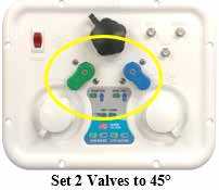
- Attach a blowout plug to the City Water Inlet on the utility center panel.
- Attach the air hose to the blowout plug. Set the compressor to 30 PSI. Green and Blue valves must be set at 45° before applying air pressure 30 PSI Max.
- Blow air into the utility center (30 PSI Max). Water lines should be clear in 5 to 10 minutes.
- Turn off the air supply, remove air hose and blowout plug.
- Close low-point drains, and replace the water heater drain plug.
- Set the water heater bypass valve to the BYPASS position. The red lever points up.
- Set the colored valves to the WINTERIZE positions.
- Green valve points left
- The blue valve points right
- Pour 1 cup of RV antifreeze into any/all drain P traps (sinks and bathtub).
- Wipe any RV antifreeze out of the sinks, shower (or tub), toilet, washing machine tub, and dishwasher tub with a soft, dry cloth.
Refer to the Utility Center manufacturer’s User Guide for additional operating information. Winterize the Black Tank Flush (if so equipped) – See the Black Tank Flush section. Winterize the Macerator system (if so equipped) – See the Macerator Pump System section.
Water Heater
Your RV may be equipped with either a tank (storage) water heater or a tankless water heater. The following is an overview of both systems.
- Hydrogen gas may result if you have not used the water heater for two weeks or more. HYDROGEN GAS IS EXTREMELY FLAMMABLE. To reduce the risk of injury under these conditions, open the hot water faucet for several minutes at the kitchen sink before you use any electrical appliance connected to the hot water system. If hydrogen is present, you may hear what sounds like air escaping through the pipe as the water begins to flow. Hydrogen gas may be present even after the water has been drained from the water heater tank. Open the faucet at the sink and allow the system to vent for five to ten minutes. Do not smoke or have any open flame near the open faucet while venting. On DSI water heater models, make sure the switch is OFF.
- Do not alter the operation or change the design/construction of your water heater. For your safety, only factory-authorized parts should be used on your water heater. Accessories marketed for recreation vehicles, such as an “add-on” electric heating elements, are not recommended by the manufacturer. Such items are not approved to be installed and could create an unsafe condition and will void all warranties.
- If you smell propane gas then STOP! and follow the procedures listed in the Propane System Section before attempting to operate the water heater.
Tank (Storage Water Heater (if so equipped)
The water heater manufacturer has preset the sensing limit to maintain the water temperature when the water heater is activated. Read the safety and operating information in the manufacturer’s user guide before attempting to activate the water heater.
Gas/Electric DSI Tank (Storage) Water Heater System (if so equipped)
Make sure the water heater is filled with water before use as even momentary operation of the water heater without water in it may result in damage to the tank and/or controls. Always open both the hot and cold water faucets when filling the fresh water tank to allow air pockets to be forced out of the water heater. The thermostat on your water heater is not adjustable and is designed to maintain a water temperature of 130°F (54°C). The water heater does not have a pilot. It is equipped with an ignition device that automatically lights the burner. Do not try to light the burner by hand.
Read all Instructions for Winterize with Air Pressure User Manual
Jayco Eagle Fifth Wheels 2023 Black Grey Water System User Manual
2023 Jayco Eagle Fifth Wheels Black Grey Water System User Manual
Black/Grey Water System and Tanks
Water from the sinks and shower flows into the gray water (or wastewater)holding tank. Water from the toilet will flow into the black water (or sewage) holding tank (see Black/Grey Water Holding Tanks).
Drain Pipes with P-Trap (if so equipped)
The drain pipes may be equipped with a “P-trap” installed to help prevent odors from escaping into the RV. During travel, water from the P-traps may spill and permit odors into the RV. By adding water and using a RV approved deodorizing agent you will dissolve the contents faster and will keep the drain lines and tanks clean and free flowing. These chemicals are available at an RV supply store or your dealer. Your RV may be equipped with a dry sealing valve that prevents the escape of odors from your waste system and eliminates the need for P-traps. Should the RV drain piping system become clogged, it is important that the dry valve be removed before passing a mechanical cleanout tool through the piping to open the drain. Passing a cleanout tool through the waterless valve may cause damage to the internal seal that may potentially allow sewer gases to escape into the RV interior. The waterless trap can be unscrewed from the water lines. A label has been placed near the location of the waste valve that reads as follows: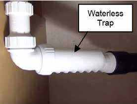
Your RV may be equipped with a dry sealing valve that prevents the escape of odors from your waste system and eliminates the need for P-traps. Should the RV drain piping system become clogged, it is important that the dry valve be removed before passing a mechanical cleanout tool through the piping to open the drain. Passing a cleanout tool through the waterless valve may cause damage to the internal seal that may potentially allow sewer gases to escape into the RV interior. The waterless trap can be unscrewed from the water lines. A label has been placed near the location of the waste valve that reads as follows:
REMOVE WATERLESS TRAP BEFORE USING MECHANICAL DRAIN CLEANING DEVICES
Sewer Hose Storage
Depending on your RV model, the sewer drain hose may be stored in an exterior compart-ment marked “Sewer Hose” or it may be located in the hollow square tube bumper. The bumper has removable plastic end caps, and the hose slides inside the hollow bumper.
Vents
Vent pipes and vents release air from the grey and black water holding tanks. On most models the exterior vent cap is attached to the roof and must be kept clear of obstructions to perform as intended. On some models, the vent pipe may be part of the drainage system referred to as a “wet vent” where water flows downward as air flows upward in the same pipe. Some models are equipped with a side vent system. On these models this label will be next to the termination valve. This label should not be removed from your recreation vehicle.
Black Grey Water Holding Tanks
Dump the gray and black water holding tanks before traveling to avoid carrying unnecessary weight. The weight of the holding tank contents is not calculated
into the RV cargo carrying capacity. Traveling with full holding tank(s) could cause you to exceed the individual tire ratings and/or the RV GAWR or RV GVWR. Potential damage to suspension components, such as springs, tires and axles, could result. If you are dry camping and cannot immediately empty your holding tanks, reduce your vehicle speed until you reach a dumping station. When connected to the sewer drain line at a campground, keep the black tank drain valve closed until the holding tank is at least ¾ full. This will provide sufficient water to assist in complete draining of the black water holding tank. Repeat as needed.
WARNING
Never travel with full black or grey water holding tanks. This not only wastes your fuel but depending on the location of the tank(s), it can affect your tow vehicle handling characteristics.
CAUTION
- Never leave the black tank drain in the open position continuously when connected to the campground sewer system. Leaving the drain open will allow the liquid to drain out increasing the potential for a blockage in the tank. Keeping the drain in the closed position will prevent debris from accumulating in the tank.
- Do not add automotive antifreeze or caustic chemicals, such as laundry detergents, into the holding tanks. Although these products may have a deodorizing effect, they may damage the plastic and rubber parts of the plumbing system or the components.
Before using the recreation vehicle, or after dumping the grey and black water holding tanks, always add the proper amount of deodorant to the black water tank to prevent odors and help break down holding tank contents (unless winterizing). Follow the deodorant bottle or package instructions. Driving to a disposal site will normally loosen any accumulated waste debris or solids from the sides of the holding tanks.
Black and Grey Tank Drains
There are labels on the exterior of the recreation vehicle indicating the location of the grey and black tank drains (also called dump valves). Depending on your model, you may have one or two valves. With one valve, the gray and black tank will release contents simultaneously. With the 2-valve set up, it is recommended that you release the black tank first, followed by the grey tank. This will help rinse and debris from the outlet and sewer hose.
- To make drainage easier, level the RV.
- Remove the sewer hose housing dust cap and attach the sewer hose (customer sup-plied).
- Place the end of the sewer hose into the approved
dump station. - Open the black tank dump valve (depending on your model the valve may be located under the RV, or on the utility center). Close the dump valve when the
black water holding tank is empty. - Open the grey tank dump valve (depending on your model the valve may be located under the RV or on the utility center). Close the dump valve when the
grey holding tank is empty. - Remove, clean and store the sewer hose.
- Close the sewer hose housing dust cap. You can locate dump stations throughout the United States and Canada in Woodall’s, Rand McNally Camp Guide, Good Sam Camp Guide, KOA Kamp grounds Camp Guide and various other publications. Some fuel stations also have dump stations. Please contact your RV dealer for assistance in the purchase and installation of a sewer hose or sewer hose extension (if needed).
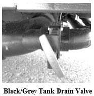
Sewage (black) tank preparation
WARNING
It is important to add enough water to prevent solid waste buildup. Follow the directions listed below and in the manufacturer’s operator manual.
- Release one to two quarts (1 or 2 liters) of water into the toilet bowl.
- Follow the directions on your RV-approved toilet chemical bottle (customer supplied) and put the recommended quantity of holding tank chemical into the toilet bowl.
- Flush the toilet and allow at least two gallons (8 liters) of water to flow into the holding tank.
Waste (grey) holding tank preparation
No special preparation is required, however, placing a small quantity of chemicals into this tank, such as baking soda or an approved RV chemical, will reduce odors from food particles in the system.
Cleaning and Maintenance
The toilet should be cleaned regularly for maximum sanitation and operational efficiency. Use only RV approved chemicals. Do not use chlorine (undiluted) or caustic chemicals, such as laundry bleach or drain opening types, in the toilet system. These products damage the seals in toilets and dump valves.
Macerator Pump System (if so equipped)
Your RV may be equipped with a macerator pump system used to discharge waste from the gray and black waste tank. The system has a 1-1/2 inch diameter flexible hose that runs from the pump (under the RV) and is stored in an exterior storage compartment. The system when powered on can discharge waste (uphill if necessary) up to a distance of 150 feet.
Read all Instructions for Black Grey Water System User Manual
Jayco Eagle Fifth Wheels 2023 Draining and Winterization User Manual
Jayco Eagle Fifth Wheels 2023 Draining and Winterization User Manual
Draining and Winterization
If the recreation vehicle is to be stored over the winter months, the water heater must be drained to prevent damage from freezing. Damage to the water heater caused by freezing is not warrantable. It is recommended the water heater be drained and bypassed during the winterization process, particularly if introducing RV antifreeze into the plumbing system. Never drain the water heater when it is HOT or UNDER PRESSURE.
To drain the water heater:
- Turn off electrical power to the water heater either at the switch from the electrical element of at the breaker.
- Shut off the propane supply to the water heater.
- Turn off the water pump.
- Open both hot and cold water faucets.
- Remove the anode rod from the tank.
For detailed information see the Winterizing the Plumbing System.
Tankless Water Heater (if so equipped)
The tankless water heater uses less LP gas than storage tank model water heaters since it only uses energy when hot water is demanded. There is no pilot light to burn when no hot water is needed. The tankless water heater supplies an unlimited supply of hot water on demand (once lines are purged of standing water). As hot water is used, the cold water enters the heater. A water flow sensor detects the flowing water and automatically ignites the burner. Water circulates through the heat exchanger and is heated to the set temperature. When the tap is closed, the unit shuts down. The tankless water heater does not require an anode rod to prevent corrosion, or a by-pass. valve for winterizing. It is not affected by high altitudes. The output temperature of the water depends on the temperature of the inlet water AND the amount of hot water that is drawn. If the inlet water temperature is over 65 º F, the tankless water heater will generate water in the range of 105°F to 120°F (on low flame) depending on the water flow selected by the user.
Operating Tips
- Purge air out of ALL hot and cold water lines.
- Open the water heater door and turn the power switch “ON”.
- Set GMC (gas modulator dial) to appropriate setting.
- Normal weather – set dial to the middle area.
- Extreme cold weather – set dial to the extreme right (large flame).
- Extreme hot weather – set dial to the extreme left (small flame).
- Open hot water faucet to a medium water flow. It may take a few seconds for the water to travel from the water heater to the faucet.
- To reduce temperature:
- Turn GMC dial “counter-clockwise”.
- Increase hot water flow.
- Gradually add cold water.
- To increase temperature:
- Turn GMC dial “clockwise”. NOTE: Use caution not to increase the dial too much which could cause the hot water temperature to rise to the point the water heater “limits’ and turns OFF the flame (flame shut off is approxi-mately 131° F).
- Reduce hot water flow.
Refer to the manufacturer’s manual for detailed operating and safety information.
Winterization
Freezing of the water heater and its plumbing components will result in severe damage not covered by warranty Follow the recommendation(s) below if the unit is to be stored in a freezing environment for a long period of time. At the start of the winter season or before traveling to a location where freezing conditions are likely, the unit must be winterized. The very small amount of water present in the heat exchanger DOES NOT require the in-stallation of a bypass kit. Refer to the Winterization section for details.
Pressure – Temperature Relief Valve
WARNING
SCALDING INJURY-EXPLOSION
- Valve is not serviceable; if defective it must be replaced.
- Tampering with valve will result in scalding injury. Do not place a plug or reducing coupling on outlet part of valve. If you use a discharge line allow complete drainage for both valve and line.
- Tampering with valve will void the warranty.
THIS VALVE IS A SAFETY COMPONENT AND MUST NOT BE REMOVED FOR ANY REASON OTHER THAN REPLACEMENT. THE PRESSURE RELIEF VALVE SHOULD ONLY BE REPLACED BY A QUALI-FIED SERVICE TECHNICIAN.
Maintenance
Inspect your water heater monthly and have it serviced at least once a year by the manufacturer’s recommended service technician. If you have questions, contact your RV dealer, the manufacturer, or Customer Service.
Outside Shower (if so equipped)
A handheld shower assembly with both hot and cold water may be included for use outside of your recreational vehicle .It may be located in a separate outside shower compartment or at the utility center (if so equipped).
- Be sure the water heater is ON and had sufficient time to heat the water.
- If dry camping, be sure the 12-volt water pump is ON.
- Remove the handheld shower from its holder.
- Turn ON the hot and cold faucet knobs, and adjust the water temperature as desired.
- To activate the handheld shower turn ON the sprayer head attachment (some models). To turn off the water always close the hot/cold control (faucet) knobs. The lever on the shower head will not completely stop the flow of water (this is intentional to allow for draining). After the water has been allowed to drain from the shower head, return it to the outside shower storage. Any remaining water in the shower hose will drip or run out; this is not a leak but performs as intended. If you are dry camping, turn the water pump OFF. Turning off the water with the shower head lever can also create a condition where the hot and cold water will mix through the outside shower faucet, thereby reducing the temperature of the hot water and give the appearance that the hot water heater is not working properly.
- NOTE: The shower head may be removed from the hose so that it will drain faster. If you remove the shower head, be sure to reassemble it prior to stor-age.
- NOTE: When putting the shower assembly back into the storage compartment, make sure the hose is not pinched or the shower head is positioned in a way it can be damaged.
Read all Instructions for Draining and Winterization User Manual
Jayco Eagle Fifth Wheels 2023 Black Tank Flush User Manual
Black Tank Flush
The black tank flush (no fuss flush) inlet is typically located on the utility center panel (if so equipped) labeled as “Tank Flush”. For models not equipped with a utility center, the inlet is located on the side of the recreation vehicle. The location may vary depending on your model. Attach a garden hose (connected to a pressurized fresh water source) to the black tank flush inlet. The water goes directly into the black water holding tank sprayer connection, allowing you to remove debris and preventing accumulation. A check valve is incorporated in the plumbing lines to prevent back flow. Flush the black water tank each time the grey and black water holding tanks are dumped or as needed.
- NOTE: Utility center (if so equipped) valve positions do not affect the tank flush function. It does not matter where they are positioned when operating the tank flush.
- NOTE: To help insure debris does not clog the tank sprayer orifices, use “TANK FLUSH” every time the waste holding tank is emptied.
- Dump the black water tank (see Gray Tank Drain & Black Tank Drain) and leave the black tank drain valve open.
- Connect a garden hose from the water supply source to the black tank flush.
- With the water source turned ON, flush the black water holding tank until the water running out of the black tank drain valve is clear (not discolored or cloudy).
- Disconnect the garden hose and close the black tank drain valve. Fasten the sewer hose housing dust cap back on the tank flush inlet.
CAUTION
- The black tank drain valve must be OPEN any time there is a hose (water supply) connected to the black tank flush.
- Do not leave any hose (water supply) connected to the black tank flush when it is not in use.
WARNING
Do not use the same hose to fill your fresh (potable) water tank that is used for the black tank flush.
Winterize the Black Tank Flush
- Black tank should be empty prior to winterizing.
- Rinse the black tank prior to blowing it out with air.
- Attach the 4” sewer hose to the dump connector under the RV.
- Open the waste gate valve for the black tank (under the RV).
- NOTE: If the RV has a macerator system, you need to open the bypass valve for the macerator under the RV. This will allow the black tank to drain through the 4” sewer hose.
- Attach a garden hose to the TANK FLUSH inlet at the utility center.
- Attach the other end of the hose to a pressurized water source. Turn water on.
- Flush tank until water appears clear in 4” sewer hose.
- Turn off water, disconnect the hose from faucet, disconnect hose from tank flush.
- Connect the blowout plug to the Black Tank Flush inlet at the utility center panel.
- Colored valves have no effect on the black tank flush inlet.
- Connect the air hose to the blowout plug. Set the compressor to 30 PSI maximum.
- Open the black tank drain gate valve, macerator bypass valve is open also.
- Blow air into the flush inlet for 30 to 60 seconds.
- Disconnect the air hose, compressor and blowout plug.
- Close the black tank drain gate valve and close the macerator bypass valve.
Draining the Spray Port
With fixtures and drain valves open in the RV to drain the water lines, connect the blue-coiled hose to the brass quick connect fitting at the Spray Port.
- Remove the spray nozzle from the other end of the hose.
- Hold the open end of the hose near the ground and any water in the line should drain out.
- Disconnect the hose from the fitting, and store in the RV.
- Close the port cover.
Winterizing the Spray Port with Antifreeze (if so equipped)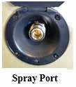
- As you are putting antifreeze into the water lines, attach the hose to the Spray Port.
- Have a container close by to capture antifreeze.
- Pull the trigger on the spray nozzle until antifreeze comes out (into the container).
- Release the nozzle and disconnect the hose from the port.
- Rinse out the hose before storing it.
Tank Heaters (if so equipped)
Your recreation vehicle may be equipped with heaters for the fresh, gray, black water tanks and the water lines or drain lines. These heaters will prevent water in the tanks and lines from freezing down to -11°F (-24°C) (contingent on recreation vehicle setup). The larger tank heaters are 120VAC and attach directly to the tanks. The thermostat con-trolled tank heaters will cycle on at 44°F (7°C) and off at 64°F (18°C). Water line or drain line heaters are smaller and operate on +12VDC and will be attached to the water lines or drain lines. The +12VDC heaters stay on constantly. All of the heaters are controlled by a single ON/OFF switch that is typically located on the command center panel or in the bathroom. The switch lights up red when ON and controls the heater circuit.
CAUTION
- In order for the 120VAC tank heaters to be in operation, the recreation vehicle MUST be hooked up to shore power or under generator power.
- If the recreation vehicle is not operating on shore power or generator power, only the +12VDC heaters will operate. This can result in the tanks freezing.
- The red light on the command center tank switch does not necessarily indicate that ALL heaters are operating; it is a only a warning that the heater circuit is ON.
The tank heater switch should be turned ON:
- When liquid is present in the holding tanks and the outside temperature approach-es and maintains freezing conditions 35°F (2°C) or colder.
The tank heater switch should be turned OFF:
- When there is NO liquid present (tanks are empty).
- When dumping the black and gray holding tanks and the drain pipes.
- When fresh water tank and supply lines are empty or being drained for storage.
- When the recreation vehicle is connected to city sewer and the gate valves are open.
- Free draining is never recommended, especially in cold weather use.
- When ambient temperatures rise and remain above freezing.
No maintenance on the heaters is required, only a periodic inspection for loose wires, dam-age, etc. For additional detailed information, refer to the tank heater manufacturer’s user guide.
Toilet
Prior to using the sanitation system, it is strongly recommended to flush the toilet several times to release sufficient water into the holding tank. Generally, more water is required only when flushing solids.
CAUTION
- It is important to prevent solid waste buildup. Follow the toilet manufacturer’s recommended instructions each time after emptying the black water holding tank.
- To help prevent toilet blockage, always use RV grade single-ply toilet pa-per. Do not flush paper towels, diapers, sanitary napkins or other foreign objects down the toilet.
- Do not use chlorine (undiluted) or caustic chemicals, such as laundry bleach or drain opening types, in the toilet system. These products damage the seals in toilets and dump valves.
The toilet system will perform better when water is run for ten to fifteen seconds after flush-ing to ensure that the waste will proceed to the bottom of the tank.
If there is not a sufficient amount of water used during flushing, the waste materials may not evacuate properly from the drain line to the tank. Clogged tanks and pipes could eventually occur. For added convenience and better sanitation system performance, it is advisable to always have four to six inches (10 – 15 cm) of water in the toilet. It is important to add enough water to prevent solid waste buildup. The following guidelines will help to prevent solid waste buildup.
Sewage (black) tank preparation.
Read all Instructions for Black Tank Flush User Manual
Jayco Eagle Fifth Wheels 2023 Air Conditioner User Manual
Air Conditioner
Cooled air enters the RV through the grill. Make sure you have sufficient power available before operating the air conditioner. Do not operate the air conditioner without the return air filter. Operating the system without the filter allows the lint and dirt that is normally stopped by the filter to accumulate on the cooling coil of the air conditioner. This also will lead to a loss of air volume, possible equipment damage, and an expensive cleaning process.
Roof Mount (if so equipped)
A special foam gasket is placed between the roof material and the subframe of the air conditioner to guard against water leakage. The air conditioner is subjected to wind pressures along with motor vibration during normal operation. Inspect the mounting bolts for tightness to ensure there is no leakage or looseness at least annually. Re-tighten bolts when they are loose. DO NOT over-tighten these bolts as it may damage this gasket. The air conditioner gasket is a wearable part that eventually will need to be replaced. To gain access to the bolts, remove the filtered panel cover on central air systems or the entire air box on non-central air conditioners.
Wall Mount (if so equipped)
Keep the air inlet grill and cabinet clean by wiping with a cloth dampened with warm water and mild detergent.
Heat Pump Operation (if so equipped)
Set the thermostat for either electric or gas heat. On the electric setting, the heat pump will become the primary heat source as long as the interior temperature of the RV has not dropped 5° below the thermostat set point. If this occurs, the thermostat will automatically activate your gas furnace.
The furnace will continue as the heat source until the thermostat set point has been satisfied. At that point, the heat pump will again become the primary heat source. For RV models with a touchscreen system, the heating and cooling controls are included on the touchscreen selectable screens. For additional information refer to the manufacturer’s owner’s manual included in your warranty packet or consult your dealer.
Power Roof Vent (if so equipped)
The 12-volt DC attic fan (or powered roof vent) allows fresh air to circulate through the recreational vehicle. Do not leave the attic fan open when the recreational vehicle is stored or unattended for long periods. High winds, other unusual conditions or obstructions may prevent the dome from closing; the resulting leakage could cause non-warrantable damage. To use your fan most effectively, close all vents and slightly open a window on a shaded side of your recreation vehicle. You are directing the air flow by opening a window. The roof vent is can be controlled by either a control pad or touch screen (if so equipped) For additional safety and operating information, refer to the manufacturer’s manual.
Ceiling Fan (if so equipped)
WARNING
Be careful to avoid placing any object in the path of the ceiling fan blades. Turn the ceiling fan ON/OFF using a switch typically located on the wall, or in an overhead cabinet. The 3-speed ceiling fan is controlled by the pull chain switch. The sequence of operation for the pull chain switch is: OFF, High, Medium, Low, and OFF. The slide switch.(located on the fan) controls the direction of operation (down for forward, up for reverse). Stop the fan first before reversing the operation direction.
NOTE: During cooler temperatures, set your fan settings to “low,” and set the fan to turn clockwise to pull warm air from the ceiling back towards the floor. In the summer, the fan should turn counterclockwise to keep the air moving. For additional information refer to the manufacturer’s owner’s manual.
Furnace
The furnace installed in your recreation vehicle is controlled by a 12-volt DC thermostat. Depending on your model, there may be up to two thermostats enabling you to control the temperature to your comfort level. The furnace requires both 12-volt power and propane gas for full operation. Make sure you have sufficient power available before operating your furnace. A qualified RV technician should perform all furnace maintenance at least once a year (more often depending on furnace usage). Never attempt to repair the furnace yourself.
Ducting and Return Air
All heat discharges, registers, and return air grills must be free and clear of obstructions. This includes all closeable registers that are intended to reduce airflow, do not shut it off completely.
- The furnace should be inspected periodically (monthly during the heating season) for presence of soot on the vent. Soot is formed whenever combustion is incomplete. This is a visual warning that the furnace is operating in an unsafe manner. If soot is observed on the vent, immediately shut the furnace OFF and contact a qualified service agency. Operating the furnace under this condition could lead to serious property damage, personal injury or loss of life.
- To ensure your personal safety, do not obstruct or alter the furnace in any manner. Do not install screens over the vent for any reason. Screens will become restricted and cause unsafe furnace operation. For your safety, only the manufacturer’s factory-authorized parts should be used on your furnace.
NOTE: For RV models with touch screens, the furnace controls may be included on the selectable menu screens of the touch screen.
Fireplace (if so equipped)
Your recreational vehicle may include an electric fireplace insert. For detailed operating and safety information, refer to the manufacturer’s user guide included in your warranty packet.
Read all Instructions for Air Conditioner User Manual
Jayco Eagle Fifth Wheels 2023 Microwave User Manual
Microwave
- To prevent damage, remove the turntable from the microwave when traveling.
- Make sure you are connected to a 120-volt power source.
Never use the microwave cavity for storage. The microwave cavity should always be empty when not in use. Never use the microwave cavity for storage. The microwave cavity should always be empty when not in use. For details on operation, cleaning, and safety information, refer to the manufacturer’s user guide.
General Cleaning Microwave and Convection Microwave
IMPORTANT: Before cleaning, make sure all controls are off and the microwave oven is cool. Always follow label instructions on cleaning products.
To avoid damage to the microwave oven caused by arcing due to soil buildup keep the cavity, microwave inlet cover, cooking rack supports, and area where the door touches the frame clean. Clean with mild soap, water, and a soft cloth or sponge, or as indicated below.
- Grease filters: mild soap and water or dishwasher.
- Door and exterior: mild soap and water, or glass cleaner applied to paper towel.
- Control panel: sponge or soft cloth and water.
- Stainless steel (on some models): mild soap and water, then rinse with clean water and dry with a soft cloth, or use stainless steel cleaner.
- Turntable: mild soap and water or dishwasher.
- Rack(s): mild soap, water, and washcloth. Dishwasher cleaning is not recommended.
Convection Microwave (if so equipped)
The convection microwave bridges the gap between microwaving your food and conventional cooking. Make sure there is sufficient 120-volt power before operating the convection microwave (see Calculating Electrical Load). for details on operation and safety information, refer to the manufacturer’s user guide.
Cooking Safety
In Case Of a Grease Fire
Do not attempt to use water to put out the fire. Water can spread some types of fire, and electrocution is possible with an electrical fire. Grease is flammable. Never allow grease to collect around top burners or on the cooktop surface. Wipe up spills immediately. Refer to Section 2 – Safety Precautions, for fire safety and fire extinguisher information.
Cooking With Propane (if so equipped)
See the Propane System section for important safety instructions. Refer to the manufacturer’s owner’s manual for detailed operating and safety instructions for all propane appliances.
Cooktops, Range, and Oven (if so equipped)
For detailed operating and safety information, refer to the manufacturer’s user guide.
- During and after use, do not touch or let clothing or other flammable material come in contact with the top burners or heating elements, burner grates or areas near the top burners or oven until they have had sufficient time to cool. These areas can get hot enough to cause burns.
- Never leave cooking food unattended. Turn pan handles inward, but not over the tops of the other range burners. Ensure that the pans used are large enough to contain the food and avoid boil-overs. Heavy splattering or spills left on the cooktop can ignite and cause burns.
- If using glass, glass/ceramic, ceramic, earthenware or other glazed utensils or cookware verify it is safe for use on the top burners.
- Do not cover the oven vent openings while the oven is in operation. Restricting the flow of combustion air will create an asphyxiation hazard.
Never use oven cleaners, chlorine bleach, ammonia, or glass cleaners with ammonia. Always allow the cooktop to cool before cleaning.
Cleaning instructions
Refer to the manufacturer’s user guide included for detailed cleaning instructions.
General Cleaning
- To avoid damage and possible burns, be sure the appliance is off and all parts are cool before handling or cleaning.
- Use care to avoid steam burns if a wet sponge or cloth is used to wipe spills on a hot surface.
- Some cleaners can produce noxious fumes if applied to a hot surface.
- To prevent staining or discoloration, clean the appliance after each use.
- If a part is removed, be sure it is correctly replaced.
- If a spillover occurs while cooking, immediately clean the spill from the cooking area while it is hot to prevent a tough cleaning chore later. Using extreme care, wipe spill with a clean, dry towel.
Electric Drop-In Cooktops (if so equipped)
NOTE: Make sure you are connected to a 120-volt power source.
CAUTION
Do not use aluminum foil under any circumstances on the electric range cooktop, as this material will damage the cooktop surface if it melts.
Gas Drop-In Cooktops (if so equipped)
Depending on your model, it may be equipped with either a 2-burner or 3-burner cooktop. The 2 burners match-light cooktop has two 6500 BTU/H burners with a control panel. The 3-burner piezo-igniter cooktop has (1) front 9000 BTU/H burner and two rear 5200 BTU/H burners. The 3-burner cooktop is also equipped with a control panel. Refer to the manufacturer’s user guide for detailed operating and cleaning information.
Read all Instructions for Microwave User Manual
Jayco Eagle Fifth Wheels 2023 Refrigerator User Manual
Refrigerator
The refrigerator is not intended for quick freezing or cooling. We recommend stocking it with pre-frozen or pre-cooled food when possible. The shelves should not be covered with paper or plastic and the food items should be arranged so air can circulate freely. Keep the area at the back of the refrigerator clean and free of debris. Check for obstructions in the exterior refrigerator vent area (i.e., spider webs, bird nests, etc.). Use a soft cloth to dust off the debris. For optimum efficiency and performance, it is recommended the refrigerator be checked at least twice a year as part of the routine maintenance. For detailed operating and safety information, refer to the manufacturer’s user guide.
Gas/Electric Models (if so equipped)
WARNING
If you smell propane gas STOP! Follow the directions located in your manufacturer’s owner’s manual and in this manual.
Residential Models (if so equipped)
NOTE: If you are using electricity to power the refrigerator, make sure you are connected to a 120-volt power source.
CAUTION
The ice maker should be turned off and the ice tray emptied when power to your motor home has been shut off. With no power, the ice will melt and water will “pool” in the refrigerator door. When power is restored, the vibration will cause this water to run out of the door and onto the motor home floor.
Cleaning Your Refrigerator
The following are general cleaning guidelines. For detailed information on cleaning your specific refrigerator, refer to the manufacturer’s user guide.
Cleaning the Interior
- Unplug the refrigerator or disconnect the power.
- Hand wash, rinse, and dry removable parts and interior surfaces thoroughly. Use a clean sponge or soft cloth and mild detergent in warm water.
- Inside the refrigerator, use a warm water and baking soda solution consisting of approximately 1 tablespoon (15ml) of baking soda to 1 quart (1 liter) of water. This solution cleans and neutralizes odors. Rinse and wipe dry.
- Leave an open box of baking soda in the refrigerator and freezer to help prevent odors.
- NOTE: Do not use abrasive or harsh cleaners such as window sprays, scouring cleansers, flammable fluids, cleaning waxes, concentrated detergents, bleaches or cleansers containing petroleum products on plastic parts, interior and door liners or gaskets. Do not use paper towels, scouring pads, or other harsh cleaning tools.
There is no need for routine condenser cleaning in normal operating environments. If the environment is particularly greasy or dusty, or if there is significant pet traffic, the condenser should be cleaned every 2 to 3 months to ensure maximum efficiency.
If you need to clean the condenser:
- Remove the base grille.
- Use a vacuum cleaner with a soft brush to clean the grille, the open areas behind the grille, and the front surface area of the condenser.
- Replace the base grille when finished.
Cleaning the Exterior
Painted metal exteriors: wash with a clean sponge or soft cloth and mild detergent in warm water. Stainless steel exteriors: wash with a clean sponge or soft cloth and mild detergent in warm water. Do not use appliance wax, polish, bleach, or other products containing chlorine on stainless steel. Stainless steel can be cleaned with a commercially available stainless steel cleaner. A spray-on stainless steel cleaner works best. Do not allow the Stainless Steel Cleaner and Polish to come into contact with any plastic parts such as the trim pieces, dispenser covers, or door gaskets. If unintentional contact does occur, clean the plastic part with a sponge and mild detergent in warm water. Dry thoroughly with a soft cloth. For silver-accented plastic parts, wash with soap or other mild detergents. Wipe clean with a sponge or damp cloth. Do not use scouring pads, powdered cleaners, bleach, or cleaners containing bleach as these products can scratch and weaken the paint finish. Replace the base grille when finished.
Washer/Dryer Prep (if so equipped)
If your recreation vehicle was built with washer/dryer prep, be aware the cabinet space provided is intended for the installation of an aftermarket washer/dryer combo unit (customer supplied) only. Please consult your dealer or the manufacturer for installation assistance. A dryer vent opening must be cut into the sidewall of the RV if installing a dryer. A label has been installed to assist you in placing the vent in the correct location. The label will be located in the area where the dryer will be installed. Instructions on how to cut the dryer vent hole and how to install the dryer vent in the wall of the RV are included in your warranty packet.
WARNING
Gas dryers should NEVER be installed in your recreation vehicle. Dryer prep has been designed for electric dryer operation ONLY.
CAUTION
Do not operate a dryer in the recreation vehicle unless the dryer is properly vented.
Central Vacuum System (if so equipped)
The following is an overview of the central vacuum system operation. For detailed operating and safety instructions, refer to the manufacturer’s user guide.
The central vacuum system installed cleans virtually any surface with no electric cords and has a variety of attachments for many cleaning needs. Make sure you have 120-volt AC power available before operating your central vacuum system (refer to Electrical Systems, calculating electrical load).
To operate the central vacuum system lift the vacuum cover, and attach your vacuum hose and cleaning attachment. The central vacuum will automatically activate. It has a large disposable bag that will need to be checked periodically and replaced after usage. The disposable bag is located inside the exterior cargo compartment.
WARNING
DO NOT PICK UP ANYTHING THAT IS BURNING OR SMOKING, SUCH AS CIGARETTES, MATCHES, OR HOT ASHES. RV damage, personal in-jury, or death may result from vacuuming up burning or smoking material. DO NOT PICK UP FLAMMABLE OR COMBUSTIBLE LIQUIDS SUCH AS GASOLINE, OR USE IN AREAS WHERE THEY MAY BE PRESENT. RV damage, personal injury, or death may result from vacuuming up flammable or combustible material.
Outside Kitchen (if so equipped)
Typically outside kitchens consist of a 2-burner cooktop, refrigerator, and sink. For detailed operation and safety information on the outside kitchen appliances, refer to the manufacturer’s user guide. The cooktop will function more efficiently when level.
WARNING
The maximum weight capacity of the outside kitchen unit is 50 lbs. Setting items on the kitchen unit that exceed this weight limit could cause damage to the unit or result in personal injury. Outside kitchen access and locking functions may vary depending on your model.
Read all Instructions for Refrigerator User Manual
Jayco Eagle Fifth Wheels 2023 Cleaning Grill User Manual
Cleaning The Grill
Make sure the grill is completely cool before cleaning. Use only non-abrasive cleaners or degreasers designed for use on stainless steel. Apply a stainless steel shine product to all external parts of your grill after cleaning. Clean the cooking grid with soap and water and a wire brush after each use. Drip pan under the grill should also be cleaned frequently. The spade (grate handle), drip pan, and cooking grid are all dishwasher safe. Use the spade (grate handle) to remove the grill grate from the grill.
Refer to the grill user guide for additional information.
Winegard Air 360 Plus System (if so equipped)
The Winegard Air 360 Plus system is a fixed omnidirectional TV/FM antenna, plus Wi-Fi, and 4G extender. The enclosure is 8 inches high and 17 inches in diameter. Antennas are powered by +12VDC supplied with a cable attached to the enclosure.
Inside the roof antenna enclosure are (3) types of antennas.
- An antenna to receive FM radio and OTA (Over-The-Air) VHF/UHF HDTV signals.
- An antenna to pick up any Wi-Fi signals broadcasting in the area.
- A 4G/LTE antenna to receive a 4G/LTE signal from your wireless cellular provider.
NOTE:
To receive 4G/LTE signal you must have a subscription to a 4G/LTE service. Connecting to the internet through a 4G/LTE connection will use data from your service provider.
A wall plate will typically be located near the main TV. The wall plate has an Antenna ON/OFF button, an antenna indicator light, a Wi-Fi ON/OFF button, a Wi-Fi indicator light, and a threaded coaxial connector for the main TV.
The first time you hook up the antenna to the TV you will need to run a channel scan to detect TV signals in your immediate area. Press the antenna ON/OFF button and the antenna indicator light comes on.
NOTE:
Winegard has two free apps that can be downloaded for Android or IPhone to help locate TV and Satellite signals: TV Signal Finder and HD Tower Finder. These apps will help you determine HDTV tower locations and satellite dish pointing coordinates.
Refer to the manufacturer’s manual for detailed connection and setup information, and for information on installing a SIM card.
Bluetooth Winegard 4GLTE Wi-Fi Router (if so equipped)
Some models will have the ceiling mounted router box as a standard item (Fig 1) installed on the ceiling positioned directly beneath antenna. Connections from the antenna to the router box are pre-wired at the factory.
In some models, the router box as optional and can be in-stalled by your dealer. The connections for the box (from the antenna) are prepped from the factory and is located behind the white cap on the ceiling (Fig 2).
The router box requires +12VDC power to operate and is controlled with a switch located on the ceiling next to the router box.
NOTE:
If the switch is left continually ON, over time it could drain your battery. When leaving the RV or when the network is not in use this switch should be turned OFF.
This router box can receive a cellular data connection through the use of a SIM card supplied by your cellular provider or through Winegard. The Winegard SIM card comes pre-installed in the ceiling router box. A second antenna in the rooftop enclosure will also pick up any wireless Wi-Fi signals in the immediate area and distribute those signals through the ceiling-mounted Winegard Gateway router box. Presently the system works with the following wireless providers: Winegard, Verizon, T-Mobile, and AT&T. A SIM card is available from your cellular provider.
Read all Instructions for Cleaning Grill User Manual
Jayco Eagle Fifth Wheels 2023 Bluetooth control User Manual
Bluetooth control
The Bluetooth function on your smartphone, tablet, or another smart device must be enabled in order to detect the SSID from the router and connect to the system.
- NOTE:
You MUSaT turn the power switch ON or there will be no cellular or Wi-Fi signals from the router box.
Router Password, Serial number, IMEI number
This information may be located in one of the following places.
- On a small vinyl tag (or label) near the entrance area to the RV. The label may be located in a nearby cabinet.
- On a tag (or label) on the Winegard Gateway instruction manual (in your warranty packet).
- On the backside of the ceiling mounted 4GLTE/Wi-Fi router box.
Resources Required:
- Mobile phone or tablet with at least IOS 9.0 or Android 4.4 with Bluetooth 4.0 capabilities.
- Bluetooth Ready Multi-Function Receiver (Pre-installed and programmed by the OEM).
- Internet Access – typically accessed through your smartphone in order to download the router setup program.
Cleaning The Interior
To keep the value of your recreation vehicle, perform regular maintenance using the proper materials and procedures. Using the wrong cleaner may result in damage to the surfaces in your vehicle. Check with the manufacturer’s information for the recommended cleaning agent. If in doubt, check to see if the cleaner will cause damage by testing a small area out of sight or contact your dealer for assistance. Do not use flammable liquids or sprays to clean the recreation vehicle.
Décor Glass (if so equipped)
Use a glass cleaner to remove smudges, smears, and spots. If there is decorative etching on the décor glass, use care when cleaning around that area.
Furniture Upholstery
Vacuum the furniture upholstery regularly using a soft brush attachment to remove any loose dirt or debris.
Fabric (if so equipped)
It is recommended the fabric be professionally cleaned if it becomes stained or soiled. The professional cleaner should be made aware of the fabrics that may have been treated to be fire-resistant. For more information, refer to the specific furniture manufacturer’s care instructions. Ultraleather™ (if so equipped): It is recommended the Ultraleather™ be professionally cleaned if it becomes stained or soiled. For more information, refer to the specific furniture manufacturer’s care instructions. Leather (if so equipped): Periodic vacuuming, using a dry cloth to wipe up spills immediately, and using a damp cloth on problem areas, will help to keep your leather furniture in good condition. Leather surfaces can vary, as do the cleaning methods. Refer to the furniture manufacturer’s recommendation, or consult a cleaning professional. It is recommended you do not use any cleaners containing oils, waxes, or silicones. Cleaners containing silicone can eventually destroy the finish of the leather. Cleaners containing oils or waxes should not be used as they leave residues on the surface of the leather, which can attract more dirt and eventually lead to cracking.
Window Treatments
Fabric – Drapes and Valances: Dust occasionally with a vacuum and soft brush attachment. It is recommended the fabric be professionally cleaned if it becomes stained or soiled. The professional cleaner should be made aware of the fabrics that may have been treated to be fire-resistant.
Window Shades
Shades should be vacuumed periodically to remove dust. Using your vacuum cleaner’s upholstery brush on low suction will remove most dust and dirt from the shade. Refer to the shade manufacturer’s owner’s manual for additional and detailed information. To remove stuck dust or stains refer to the following guide.
Solar Shields:
Use a sponge or soft brush and water to remove stains. A mild cleaning solution can be used to remove tougher stains. Rinse after cleaning by wetting a clean cloth in fresh water, wringing out any excess, and wiping the areas where the cleaner was used.
Day/Night Shades:
Clean with a mild cleaning solution using a sponge or paper towel. Wipe down with water after cleaning and dry thoroughly before raising the shade. Do not use spot remover, household cleaners, or detergents to remove soiled spots, as these may cause damage to fabric or loss of color from fading.
Mini Blinds:
A simple dry rag may do the trick. If they are especially dirty, you can use cold or warm water to clean them; never use hot water.
Read all Instructions for Bluetooth control User Manual
Jayco Eagle Fifth Wheels 2023 Roller Shades User Manual
Roller Shades
Clean by using soapy water or a mild cleaning solution on spots. Try a small area first because harsh household cleaners or detergents may cause damage to fabric or loss of color. It is recommended to dust the rails and fabrics of the shades on a regular basis. Shades should be kept in the closed or up position when not in use to maintain pleat retention and minimize dirt and soil build-up.
NOTE:
If your recreation vehicle must be stored for an extended period of time, store shades in the up position and cover your windows with additional protection (I.E. Cut out cardboard).
Cabinetry and Tables
To keep hardwood doors, cabinet fronts, and hardwood tables looking like new regular dust with a soft cloth dampened with a cleaning polish or mild detergent solution. Avoid using ammonia-based products or silicone oils as they may cause damage if used over a long period of time. The finish is durable and resistant to most household spills. However, spills should be wiped up promptly to avoid potential problems. Excessive prolonged exposure to direct sunlight, high temperatures, and high humidity can cause damage to both the finish and the wood itself.
Interior Wall Panel
To clean, use a mild solution of soap and lukewarm water with a soft sponge or cloth. Wipe dry with a soft, clean cloth. Putty sticks can be used to cover scratches on the wood surface wall panels. These can be obtained from local hardwood stores and lumberyards. Contact your dealership service department for assistance in repairing décor paneling.
Caution
Do not use abrasive cleaners as they may cause the vinyl to scratch and become dull. Do not use cleaners that contain bleach.
ABS Plastics
Dust and wipe clean with a soft, damp cloth or chamois, wiping gently. Do not use gritty or abrasive particle soaps or scouring compounds to clean ABS plastic. Avoid using “citrus” or biodegradable cleaners that contain “D-Limonene” as they may damage plastic materials.
Sofa and Dinette
Your recreation vehicle may be equipped with one of the following sofa styles.
Hide-A-Bed Sofa or Sofa Sleeper
To make the hide-a-bed sofa into a bed, remove the seat cushions and pull the sofa back towards you firmly and gently. Activate (or deflate) the air mattress (if so equipped) using the supplied furniture manufacturer’s instructions. To convert the hide-a-bed back into the upright sofa position, reverse the process.
Jack Knife Sofa
The jack knife sofa functions much the same as a residential futon. To make the sofa into a bed, lift up the bottom seat cushion and pull it towards you. The sofa’s back will drop. down to provide a sleeping surface. For additional comfort and to reduce fabric damage, you may want to place a cover or air mattress (customer supplied) over the sofa when it is in the sleeping position.
Trifold Sofa
The tri-fold sofa offers very similar features to a traditional hide-a-bed. To convert the sofa into a bed.
- Remove the tri-fold sofa pillows and set them aside.
- Using the strap handle, pull the sleeping surface up, then out.
- While the sleeping surface is up, fold-out legs. Extend the sleeping surface until grounded.
- Once the sleeping surface is grounded, fold the headboard down flat.
Cube Sofa
The Cube Sofa functions similarly to a residential futon. The slanted back pillows offer numerous options as a sofa, along with the ability to extend the cushions for additional sleeping space.
Booth Dinette (if so equipped)
The dinette is designed to seat up to four adults. Depending on your model, there may be a storage area in the dinette bench. To access this storage, remove all the cushions and lift up on the bottom seat support. If the bottom seat support is secured closed with screws, do not remove the seat support or use this area for storage. The dinette seats that are secured with screws contain factory-installed equipment and should only be accessed by a qualified service technician.
Converting the dinette to the bed position
Remove all the cushions from the booth dinette. Lift up the tabletop and remove the detachable table legs. Place the tabletop on the ledges provided between the booth dinette benches. Lay the seat back cushions against the back of the dinette bench. Lay the dinette seat bottom cushions in between the seat back cushions. The area where the cushions meet should be slightly raised. Push the raised cushion ends down gently as the cushions are designed to fit snugly. Reverse this process when converting back to the booth dinette.
Free-Standing Table and Chairs (if so equipped)
The free-standing dinette table can be positioned to seat up to four people. To prevent damage, the free-standing dinette chairs should be fastened securely at the dinette table when traveling.
Read all Instructions for Roller Shades User Manual
Jayco Eagle Fifth Wheels 2023 Pantry or Hutch User Manual
Pantry or Hutch
Your recreation vehicle may have a pantry or hutch that you can use for storage. Make sure all items stored in the pantry or hutch are secured to prevent shifting during travel. This cabinetry has been designed to accommodate normal camping items which may be bulky but not necessarily heavy. Remember your recreation vehicle’s load capacity is designed by weight, not volume, so you cannot necessarily use all available space. If your pantry or hutch has sliding pantry shelves, they have been equipped with a locking mechanism to keep them in place during transit. To secure the shelf in place, push it all of the way in until the latch tab clicks into place. Always pull out slightly on the shelf to make sure that it is stationary and secure in the transit position. To release the shelf, push in on the tab and pull the shelf slowly towards you.
Warning
Your RV’s load capacity is designated by weight, not by volume, so you cannot necessarily use all available space when loading the vehicle. Do not exceed your GVWR and ensure you are loading the vehicle as evenly as you can for the best possible handling. Ensure heavy items are secured so they do not shift during travel.
Countertops
To prevent permanent damage
- Always use hot pads or trivets under hot pans, dishes, or heat-producing appliances.
- Heat will damage countertops.
- Use a cutting board to prevent unnecessary damage to the countertops
- Avoid harsh chemicals such as drain cleaners, oven cleaners, etc.
- Do not let cleaners with bleach set on the top. Wipe them off promptly.
- Run cold water when pouring hot/boiling water into the sink.
- Use coasters under all glasses, bottles, and cans.
- Do not store toiletry products directly on your countertop surface. Hair products, perfumes, colognes, nail products, creams, lotions, and potions have a tendency to spill or leak and go overlooked. Even though the countertop is sealed, a substance that remains on the surface for an extended period may stain the countertop.
For additional information on the removal of difficult stains or surface damage repair, refer to the countertop manufacturer’s user guide.
Laminate Countertops (if so equipped)
Glass rings, food spills, water spots, and smudges usually wipe off with a damp sponge. Stubborn stains can be removed with a general-purpose spray cleaner. Some stains can be removed by squeezing fresh lemon juice over the stain and allowing the juice to soak for approximately forty-five minutes. After 45 minutes, sprinkle baking soda over the lemon juice and rub with a soft cloth.
Solid Surface Countertops (if so equipped)
Soapy water, ammonia-based cleaners (not window cleaners as they can leave a waxy build-up that may dull the surface), or commercially available solid surface cleaners will remove. most dirt and residue from all types of finishes. A damp cloth followed by a dry towel will remove watermarks.
Difficult stains can be removed from the matte finish with a green Scotch Brite® pad and a mild abrasive cleaner. Disinfect the surface periodically with diluted household bleach (one part water to one part bleach). For cuts and scratches, the matte finish lightly with (220) fine grit sandpaper until the cut or scratch is gone. Restore the finish with a green Scotch Brite® pad and mildly abrasive cleaner.
Solid surface sink maintenance
Occasionally, clean the solid surface sink by filling it one-quarter full with a 50/50 water/bleach solution. Let soak for 15 minutes, and then wash the sides and bottom of the sink as the solution drains.
Quartz Countertops (if so equipped)
- Quartz will absorb heat from the pan. Resin in the countertop can withstand temperatures of 150°. Do not place a hot pan (from stove or oven) on a quartz countertop as it will burn or cause permanent damage. Heat will damage the solid surface countertops.
- Quartz is highly scratch-resistant and stain-resistant but prolonged exposure to sunlight can eventually damage a Quartz countertop.
NOTE:
Only have a professional fabricator repair
Cleaning your countertop
To keep quartz countertops clean, wipe up spills immediately before they have a chance to dry. Use mild dishwashing soap and a soft cloth. For dried spills a non-abrasive sponge (designed for nonstick pans) works well along with a little elbow grease. Keep a plastic putty knife handy for scraping off gum, nail polish, paint or other messes.
Remove cooking grease using a degreasing product that will loosen then remove the grease. Follow cleanser manufacturer instructions. For stains like permanent markers moisten a cloth with Goo Gone (or similar) and rub it into the stain. Rinse with warm water. General deep cleaning is recommended at regular intervals using a nonabrasive surface cleaner on the countertop. Let it sit for 10 minutes and wipe it with a non-abrasive sponge.
- Never use abrasive cleansers and avoid scouring pads. If you need a gentle cleanser to remove stains make sure it is specifically designed for Quartz.
- Do not use nail polish remover, turpentine, drain cleaner, and dishwashing rinsing agents. You may use diluted bleach or a mild bleach cleanser, but oven cleaners or concentrated bleach should never be used. If they come in contact with the countertop, rinse immediately with water.
Read all Instructions for Pantry or Hutch User Manual
Jayco Eagle Fifth Wheels 2023 Flooring User Manual
Flooring
Carpet
Vacuum your carpet regularly. It is important to remove loose soil and debris while it is on the surface. Heavily traveled areas (i.e., walkways, and areas in front of the furniture) may be protected with small throw rugs to prolong the life of the carpet. Prompt attention to spots and spills is essential. Remove as much of the spill as possible. Absorb wet spills as quickly as possible by blotting repeatedly with white paper or cloth towels. Refer to the manufacturer’s guide for detailed cleaning information, or contact a cleaning professional.
Vinyl Flooring (if so equipped)
Periodically vacuum or sweep to remove dirt and gritty particles. Although most common spills will not permanently stain the vinyl floors, they are usually easier to remove if wiped up before they are set. Blot with a paper towel and wipe clean with a damp cloth. Do not use dish detergents or vinegar and water because they will dull your floor.
To care for the vinyl floor covering, use a damp mop with water and a mild cleaner on the entire floor. DO NOT SOAK THE FLOORING. Use care to avoid wetting the carpet edges. To avoid problems of “yellowing” linoleum, the flooring manufacturer recommends avoiding cleaners that contain oil-based solvents (i.e. lemon oil, Murphy’s Oil Soap, etc.).
Ceramic Tile (if so equipped)
Vacuum the ceramic floor tiles regularly to remove dirt and other gritty particles, then damp mop or sponge with an all-purpose, non-oil-based cleaner. Heavily trafficked tile may require more intensive cleaning. Refer to the manufacturer’s guide or contact a cleaning professional for detailed cleaning information.
Grout, the material used between the tiles is porous, and sealing it will simplify maintenance in the future. The ceramic tile manufacturer recommends applying a sealer at least twice a year for maximum stain protection. Sealers may be purchased at most local home centers or floor-covering stores.
DO NOT:
- Use cleansers containing acid or bleach for routine maintenance.
- Use wax cleaners, oil-based detergents or sealants to maintain your tile (sealants may be used on grout joints and natural stone).
- Use ammonia (it will discolor grout).
- Use harsh cleaning aids like steel wool pads or scouring pads containing metal.
- Use a cleaning agent that contains color on unglazed ceramic tile or natural stone.
- Test scouring powders on a small area first (not recommended for natural stone).
- Use a sealer on grout joints.
- Have any damaged or broken tiles replaced only by a qualified contractor.
Murphy Bed (if so equipped)
Your recreational vehicle may be equipped with a folding Murphy bed. When in the closed position, the bed is stored in the wall allowing for more living space within the vehicle. When you want to use the bed, the sofa folds flat and the bed can be pulled down over the sofa into the sleeping position.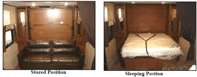
Caution
The slide-out must be fully extended before putting the Murphy bed in the sleeping position. The Murphy bed must be in the stored position before the slide out can be moved to the in (travel) position. Failure to do so may result in injury or property damage. This label has been installed in your recreational vehicle at the foot end of the Murphy bed. It should not be removed.
Unfolding the Sofa
With the slideout fully extended, unfold the sofa into a flat position.
Lowering the Murphy bed
- Unlatch the “D” bolt latches on each side of the bed at the footboard (in the stored position). This will release the Murphy bed allowing it to unfold.
- Firmly grasp the handle on the footboard of the Murphy bed, and pull it towards you.
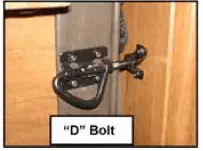
- The bed will begin to unfold. Pull it all the way down so the footboard rests on the floor.
- When the bed is in the sleeping position, locate the web straps with snap hooks on the footboard of the bed (there is one on each side of the bed). Attach (both) snap hooks to the metal loops located on the sofa arms. These straps and loops keep the bed from folding up while in use.
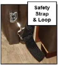
NOTE:
The straps are adjustable. They have been installed at a length that holds the bed securely in place and allows ease of attaching the snap to the metal loops.
Read all Instructions for Flooring User Manual
Jayco Eagle Fifth Wheels 2023 Storing Murphy Bed User Manual
Jayco Eagle Fifth Wheels 2023 Storing Murphy Bed User Manual
Storing the Murphy Bed
- Attach the “Y” strap that holds the mattress to the bed frame. Pull the straps with the buckles up from the head of the bed and snap them to the “Y” strap. Secure the snap hook at the footboard. MAKE SURE THE SAFETY STRAPS AT EACH SIDE OF THE FOOTBOARD ARE STILL ATTACHED TO THE STEEL LOOPS ON THE SOFA ARMS BEFORE PUTTING ANY WEIGHT ON THE BED.
- Unhook the safety strap snap hooks from the steel loops on the arms of the sofa.
- Release the locking lever (if applicable) so the bed can be raised.

Warning
Keep hands and fingers away from the collapsing footboard and struts when pushing the bed back in to the storage position.
- Push the bed back up into the storage position.
- Secure the two “D” bolts on each side of the bed.
- Flip the sofa back up into the seated position:
- Firmly grasp the edge of the top cushion and the front edge of the seat cushion.
- Push the cushions down and towards each other so they form a “V” shape.
- While holding the cushions in this “V” shape, rotate the sofa back towards the wall and the cushions will revert to the seated position.
Bed Storage
Additional storage has been provided under the bed. To access the storage area, grasp the ledge at the foot of the bed and lift carefully. The bed platform must be held when raised. It is recommended that two people retrieve stored items from under the bed so that one person may hold the platform, and the other can retrieve the stored items from under the bed. Lower the platform slowly to close it. DO NOT DROP THE PLATFORM.
Warning
- Before lifting, be sure there is nothing on the bed that will restrict its movement or add extra weight.
- Use caution when opening or closing the bed to keep hands and fingers at the end ledge provided (not on the side or farther back than necessary).
- Exercise extreme caution when opening the bed storage platform. Plat-form must be held open (unless equipped with a prop rod or gas struts) and slowly lowered until closed.
- The bedroom electric slide room system may be located under the bed. Use care not to obstruct the slide room system when using the under-bed storage.
- Failure to comply with these guidelines can result in serious injury or property damage.
Some models may be equipped with a prop rod or gas struts to assist with easy access to under-bed storage.
Prop Rod (if so equipped)
If your model is equipped with a prop rod:
- With the help of a second person, raise the bed platform.
- Release the prop rod from its holder.
- Put the end of the rod in the bracket under the bed platform.
- To lower the platform, release the prop rod from the bracket under the bed platform, re-attach the prop rod to the holder on the bed base,
- Lower the platform slowly until closed.
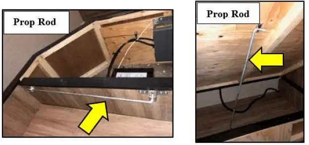
Gas Struts (if so equipped)
On certain models, the bed platform may be equipped with gas struts to assist with easy access to the storage area.
- Grasp the ledge at the foot of the bed and lift carefully.
- Two gas struts will hold the bed platform open allowing access to the storage area.
- To close, carefully push down on the bed, slowly easing it to the closed position.
Loft Sleeping Area (if so equipped)
Your RV may be equipped with a loft sleeping area. Access to the loft sleeping area is through the use of a (wood or steel) ladder. The steel ladder is equipped with hooks that fit over the sideboard of the loft bed. Typically the wood ladder is attached to a closet door (or wall) and pivots out for use (A & B). Be sure the door is closed and latched, and the ladder is securely in place before climbing up to the loft area. When storing the ladder, make sure to buckle the security strap which keeps the ladder in place in it.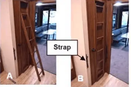
Warning
- Exercise extreme care when climbing up or down the ladder used for entering or exiting the loft bed.
- The closet door MUST be securely closed and latched before using the ladder.
- Make sure the ladder is securely in place prior to climbing to or from the loft.
- Never allow more than one person on the ladder at a time.
- Make sure the wood ladder attached to the door (if so equipped) is locked back into position on the door when not in use to prevent a trip hazard.
- Security straps must be buckled across the ladder when in the stored position.
- Do not leave small children unattended in the loft area.
- The maximum weight rating for either ladder type is: 300 lbs (136 kg)
- Weight ratings for loft sleeping areas may vary by RV type and model:
- Refer to the maximum weight rating label located at the loft sleeping location.
- Never allow anyone to ride in or occupy the bed while the recreational vehicle is in motion.
- Do not use the loft sleeping area for storage while the vehicle is in transit. Loose items may become projectiles.
- Failure to follow these instructions can result in serious bodily injury.
Read all Instructions for Storing Murphy Bed User Manual
Jayco Eagle Fifth Wheels 2023 Bunk Beds and Ladders User Manual
Jayco Eagle Fifth Wheels 2023 Bunk Beds and Ladders User Manual
Bunk Beds and Bunk Ladders
Your recreational vehicle may be equipped with bunk-style beds. Bunk bed weight ratings may vary depending on your model and the style of the bunk bed. Weight capacities are listed on the bunk capacity label. Do not exceed the bunk weight capacity.
Bunk Ladders (if so equipped)
Your recreational vehicle may be equipped with a ladder to access the upper bunk. This ladder may be a separate steel ladder or a wooden ladder attached to the bunk beds.
The top of the ladder is secured to the ladder storage compartment. To operate the ladder, lift up and out of the storage tray. Pivot the bottom of the ladder out. Be sure the ladder is securely in place on the floor before climbing to the upper bunk. When storing the wood ladder, place the bottom of the ladder back into the tray in the storage compartment. This keeps it secure during transport and clear of walkways. The steel ladder (if equipped) will simply hook onto the upper bunk.
NOTE:
Some types of bunk beds do not include a ladder.
Warning
- Exercise extreme care when entering or exiting the bunk beds and using the ladder.
- Do not allow more than one person on the top bunk.
- Do not allow children under 6 years of age to use the upper bunk.
- Do not allow horseplay on or under the bed and prohibit jumping on the bed.
- Make sure the ladder is anchored properly to the bed.
- Never allow more than one person on the ladder at a time.
- Children should always be supervised when using the ladder or when entering or exiting the bunk beds.
- The weight limit of the bunk ladder is 300 lbs. (136 kg). Never exceed this weight.
- Maximum weight limits for bunk beds will vary depending on the model or bunk style. Never exceed the maximum weight specified on the bunk capacity label.
- Failure to follow these instructions can result in serious bodily injury.
Cleaning The Exterior
To protect your recreation vehicle’s exterior finish, wash it often and thoroughly. You may wash and wax your new recreation vehicle 60 days after purchase. The exterior paint needs time to cure before any wax is applied to the exterior surface. Careful maintenance for the first 60 days will assure a long-lasting durable finish.
Your RV is exposed to many environmental conditions that have an adverse effect on the paint finish:
- Road Salt and Sodium Chloride
- Road Tar / Bugs
- Bird Droppings / Tree Sap
- Industrial Fallout / Acid Rain/Pollution
- UV Exposure and Moisture
The most common problems resulting from these conditions are corrosion, staining, and chemical spotting. Generally, the longer the foreign material remains in contact with the exterior finish the more extensive the damage. These problems can be minimized by regularly scheduled washing and polishing. Wash your recreation vehicle as soon as possible if it becomes contaminated with foreign material. Avoid parking under trees or near ocean sea salt. Ice or snow should be brushed off, not scraped, from the painted surface. Avoid gravel roads. Anti-freeze, gasoline or washer solvents if spilled on the painted surface should be rinsed off with water immediately. Bugs and bird droppings should be rinsed off daily.
Washing
Commercial washing should be avoided. Wash with cold water using a mild liquid soap. Dry wiping with a dry cloth is not recommended.
Make sure the RV’s surface temperature is cool, under 90 F, and out of direct sunlight. A shaded area is ideal for washing your vehicle as direct sunlight causes water spotting. Use a mild soap, detergent or car wash shampoo. Try to avoid combination wash-n-wax products as these waxes can cause build-up and are designed for smaller surfaces. Have two dedicated sponges or wash mitts: one for the paint finish and one for the wheels and undercarriage. Brushes or wash mitts made of plastic bristles are acceptable for use on tires and wheel wells but are not intended for use on the paint finish. Avoid using such items on painted surfaces as they will damage the finish. Wash the wheels and wheel wells first as this removes heavy dirt and debris and prevents it from splattering on panels. Wet the entire area down to remove loose dirt and grime, then hand washes one area at a time using your dedicated paint finish sponge or wash mitt. Wash from the top and work your way down, rinsing frequently to minimize grit abrasion. Follow with a final rinse of water. This process will remove most contamination from the RV’s surface.
For stubborn stains such as road tar or bug stains, use an ammonia-based glass cleaner or a small amount of rubbing alcohol on a damp cloth followed immediately by warm soapy water, and rinse with clean water. This may not dissolve the road tar, but it will loosen tar and bug stains and remove them from the surface.
Do not use solvent-based cleaners on bird droppings or tree sap as these are water-based stains. They can be dissolved using an ammonia-based glass cleaner, warm soapy water, and a little “elbow grease”. After removing stubborn stains immediately rinse with clean water. Drying the RV is just as important as washing it. Tap water and well water contain many chemicals that could water stain your RV’s finish. We suggest using a damp natural or synthetic chamois. There are other drying products such as lint-free micro-fiber towels that work just as well.
Read all Instructions for Bunk Beds and Ladders User Manual
Jayco Eagle Fifth Wheels 2023 During cold weather User Manual
Jayco Eagle Fifth Wheels 2023 During cold weather User Manual
During cold weather
Salt and other chemicals that are spread on winter roads in some geographical areas can have a detrimental effect on the recreation vehicle’s underbody.
If your recreation vehicle is exposed to these conditions, spray the underbody with a high-pressure hose every time you wash the exterior of your recreation vehicle.
Take special care to remove mud or other debris that could trap and hold salt or moisture. After washing your recreation vehicle, wipe off all water drops from the rubber parts around the slideout and doors.
NOTE:
When the slideout or door is frozen, opening it by force may tear off or crack the rubber gasket that is installed around the slideout or door. Pour warm water on the gasket to melt the ice (wipe off the water thoroughly after opening the slideout or door). To prevent the weather stripping from freezing, treat it with a silicone spray.
Waxing
Wax your recreation vehicle once or twice a year, or when painted surfaces do not shed water well. Use a soft cloth to apply a small amount of wax to the painted surfaces. After the wax has dried, polish the recreation vehicle with a dry, soft cloth. Do not wax your recreation vehicle in direct sunlight. Wax it after the surfaces have cooled. Do not apply wax to any area having a flat black finish as it can cause discoloration. If the finish has been stained with wax, wipe off the area with a soft cloth and warm water. When waxing the area around the various openings, do not apply any wax on the weather strip. If it is stained with wax, the weather strip cannot maintain a weatherproof seal around the opening.
Caution
- Do not use waxes containing high-abrasive compounds. Such waxes remove rust and stains effectively from the paintwork, but they are also harmful to the luster of the painted surface since they scrape off the coating. Further, they are detrimental to glossy surfaces, such as grille, garnish, moldings, etc. Do not use gasoline or paint thinners to remove road tar or other contamination from the painted surface.
- Do not use a buffer and a buffing compound as it may damage the exterior surface. Please contact a professional paint body shop for assistance.
Polishing your recreation vehicle
If painted surfaces have been severely damaged and have lost their original luster and color tone, polish the surface lightly with a fine polishing compound. Avoid limiting your polishing to the damaged surface only; polish a somewhat wider area, moving the polishing cloth in one direction. After polishing, flush the compound from the surface and apply a coat of wax to regain a beautiful luster.
Damaged paint
To prevent corrosion, touch up small cracks and scratches in the paint coat as soon as possible with touch-up film or paint. Carefully check the body areas facing the road and the tires for damage to the paint coat caused by flying stones, etc.
Cleaning plastic parts
Use a sponge or chamois to clean plastic parts. Use warm water and a soft cloth or chamois to remove any white residue from dark-colored plastic surfaces. Do not use a scrubbing brush, other hard tools, or wax-containing abrasives as they may damage the plastic surface.
Caution
Do not allow the plastic to come into contact with brake fluid, engine oil, grease, paint thinner, or battery acid. These will damage the plastic. Use a soft cloth and a mild detergent solution to wipe away any such contact.
Chrome parts
To prevent chrome parts from spotting or corroding, wash with water, dry thoroughly, and apply a non-abrasive automotive wax. If the chrome is severely damaged or pitted, use a commercially available chrome polish product.
If your recreation vehicle is exposed to these conditions, spray the underbody with a high-pressure hose every time you wash the exterior of your recreation vehicle.
Take special care to remove mud or other debris that could trap and hold salt or moisture. After washing your recreation vehicle, wipe off all water drops from the rubber parts around the slideout and doors.
Read all Instructions for During cold weather User Manual
Jayco Eagle Fifth Wheels 2023 Frame User Manual
Frame
Sand, pebbles, objects on the highway, climate (salt air exposure) or ice-inhibiting chemicals used during the winter months will damage the paint, inviting rust and other deterioration. Periodically inspect the exterior exposed areas, clean and repaint the frame members occasionally, and whenever you notice rust or paint chipped away, to insure protection.
E-Z Lube or Super-Lube Axle (if so equipped)
The E-Z lube or Super-lube feature on your axles provides the ability for the bearings to be periodically lubricated without removing the hubs from the axle. This feature consists of axle spindles that have been specially drilled and fitted with grease zerks in their ends. When grease is pumped into the zerk, it is channeled to the inner bearing and then flows back to the outer bearing and eventually back out the grease cap hole. If you have further questions, consult with your dealer.
NOTE:
The convenient lubrication provisions of the E-Z lube or Super-lube feature must not replace periodic inspection and maintenance of the bearings. Use a hand-operated grease gun; improper use of a commercial grease gun may damage the seals.
Exterior Roof and Sidewall Vents
Inspect the roof vents, including sealants for cracks and keep them clean. Inspect the refrigerator and holding tank vents for blockages from bird nests, spider webs, leaves, etc. All exterior access doors and vents need to be kept clean and free of obstructions (i.e., insect nests, mud daubers, etc.) while the appliances are in use.
Windows
Any ventilating window may permit water inside, especially during heavy rainstorms. Condensation will also cause water to accumulate on windows and in the tracks.
Window glass
The window glass can normally be cleaned with a sponge and water. Use glass cleaner to remove wax, oil, grease, dead insects, etc. After washing the glass, wipe it dry with a clean, soft cloth.
Exterior Ladder (if so equipped)
Your recreation vehicle may be equipped with an exterior roof ladder. The RV roof has decking under the rubber roof membrane to allow you to walk on the roof (with caution) to do maintenance.
Warning
- If your recreation vehicle is equipped with a roof ladder, do not leave items attached to it while traveling. DO NOT exceed the weight rating of the ladder. The ladder weight capacity label is located under the bottom step of the ladder. There should never be more than one person on the ladder at the same time.
- Self-Storing ladders: Make sure to pull all pins (there may be up to 4) to unlock the ladder. All pins must be re-inserted when locking the lad-der open for use.
LADDER CAPACITY MAXIMUM 300 lbs. (136 kg)
- DO NOT exceed the ladder maximum weight rating.
- The maximum rating includes the person’s weight PLUS weight of items carried.
- When climbing:
- Always face the ladder.
- Climb slowly with weight centered between side rails.
- Keep a 3 point contact on the ladder at all times (3 Point contact-two hands and a foot or two feet and one hand).
- Keep hands free.
- Use of accessories such as lanyards to keep carried items tethered will keep hands free and prevent falling items.
- Heavy or bulky items should be brought up only after reaching the roof.
- Do not use the ladder if damaged in any way.
Failure to follow these guidelines could result in death or serious injury.
Some models may be equipped with a self-storing ladder mounted to the side of the vehicle. Self-Storing Ladder operation
- Pull all the locking pins out of the ladder brackets (Fig. A).
- Pull the ladder down and toward you and it will swing away from the RV.
- When the brackets are extended (Fig. B), re-insert the pins to lock the ladder in place while in use.
- To return the ladder to the storage position; pull the locking pins and push the ladder up and in towards the RV.
- When the ladder is in the storage position, re-insert all locking pins to prevent the ladder from opening while traveling.
Read all Instructions for Frame User Manual
Jayco Eagle Fifth Wheels 2023 Sealants User Manual
Sealants
Caution
- Failure to properly maintain or reseal your recreation vehicle may result in serious water damage to the roof and other parts of the recreation vehicle. This damage is not covered by the Limited Warranty.
- To check the exterior sidewall sealants, use a stepladder placed safely alongside the vehicle. Do not prop a ladder against the body of the RV as it may damage the exterior finish.
Sealants perform a very important function and should be inspected closely and regularly maintained. We incorporate many different types of sealants, including butyl/putty, black butyl-encapsulated foam, silicone (clear and colored), roof sealant and foam. In general, sealants do not have “set” lifetimes. Varying environmental factors affect the pliability and adhesiveness of sealants.
You or your dealer must:
- Inspect all sealants, a minimum of every six months. Make sure to check the roof and all four sides of the recreation vehicle including al moldings, doors, vents and exterior attachments. A quick walk around the recreation vehicle before leaving may help prevent potential problems during trips and vacations.
- Have the sealant replaced if you notice any cracks, peeling, voids, gaps, breaks, looseness or any sign of physical deterioration? Reseal at least one time each year as preventative maintenance.
- Always use the same type of sealant that was removed. Your dealer service or parts manager can help you obtain the correct sealant(s).
Fifth Wheels – Sealant Diagram
Travel Checklist
Following is a preliminary list of items that need to be checked before leaving your home or campsite. This is a general list, which you may want to customize as you determine your own needs.
Safety
- Make sure you follow all safety precautions noted in this owner’s manual and in any manufacturer’s operator’s manual when preparing to travel.
Maintenance
- Inspect seals and reseal as needed.
- Have the propane system checked for leaks by your dealer.
- Check wheel lug nuts after first two hundred miles and at specified intervals to listed torque specifications, re-torque as needed.
- Have brakes been adjusted by a qualified service technician?
- Sanitize the freshwater system.
- Test the safety alarms.
Before leaving home (or campsite)
- Make sure all tow vehicle fluids are at proper levels. Check the engine oil, transmission fluid, engine coolant, power steering fluid and wind shield washer fluid.
- Check the lights on the RV. Have someone observe the operation of all exte-rior lights while you activate the controls. Check the turn signals and brake lights.
- Examine the tires for excessive tread wear or uneven wear patterns. Check for stones, nails, glass or other objects lodged in the tread. Inspect for tread cuts or sidewall cracks.
- Check tire pressure (including spare) and correct according to manufacturer specifications.
- Check wheel lug nuts for tightness.
- Inspect safety chains for signs of wear.
- Inspect and work all interior and exterior latches and locks (lube if necessary).
- Make sure the batteries are fully charged and installed correctly.
- Inspect the power cord and carefully clean the contacts if necessary. Plug in the power cord to an appropriate power source.
- Turn on the interior lights and check outlets for polarity. If needed, replace any blown fuses. Check the circuit breakers and test the GFCI.
- Check the propane cylinder gauge to make sure there is propane available. Make sure the propane cylinder is in place and secure for transport.
- Inspect and turn on the propane system. If you have any questions, contact your dealer or a qualified propane service representative for assistance. If the propane system is functioning properly, test any pilot lights or direct spark igni-tion features.
- Inspect and test all safety detectors. If needed, replace any drained or discharged batteries. If you have a defective or damaged safety detector, replace it immediately.
- Inspect the leveling jacks (if so equipped) for operation. If needed, perform maintenance as specified by the leveling jack manufacturer.
- Test all exterior and interior lights. Replace any bulbs if they are burnt out.
- Wash the exterior of the RV. Do a sealant inspection and repair as necessary.
- De-winterize and sanitize the freshwater system.
- Connect your tow vehicle to the RV and test all connections and lights.
- Test brakes.
Read all Instructions for Sealants User Manual
Jayco Eagle Fifth Wheels 2023 Before leaving campsite User Manual
Jayco Eagle Fifth Wheels 2023 Before leaving campsite User Manual
Before leaving the campsite
- Check the area under the RV after overnight parking and look for water or other fluid leaks. If leaks are detected, find the cause and correct it immediately.
- Turn off propane tanks.
- Empty black and gray holding tanks, rinse as needed (if so equipped).
- Retract awning and secure in place for transport (if so equipped).
- Close roof vents.
- Close windows & latch blinds.
- Disconnect any cable TV or phone hookup, and lower the TV antenna (if so equipped).
- Turn off interior lights.
- Turn off water heater, water pump, furnace and appliances.
- Snap the Range Hood vent closed (if so equipped).
- Latch drawers, cabinets & doors. Counter items put away or tied down.
- Fasten and secure the furniture for travel (if so equipped).
- The refrigerator door locked (if so equipped). Set to 12-volt (if applicable).
- Secure any loose, heavy or sharp objects in the RV or exterior compartments.
- Disconnect the power cord and ensure it is stored correctly.
- Disconnect any water connections.
- Fasten all interior and exterior doors securely. Lock them (if so equipped).
- Move slideout(s) in and lock it in place (if so equipped).
- Walk around your RV one last time to make sure everything is stored away and the baggage compartments are closed and locked.
- Retract leveling jacks to the travel position (if so equipped).
- Retract step.
- Secure and lock the entrance door.
RV Storage
Properly preparing your RV for storage during periods of non-usage will prevent problems from arising. It will also make it easier to get started again for the following camping trip or season. To prevent costly freeze-ups, winterize the plumbing system when it will not be in use for an extended period of time, especially if it is stored in colder climates.
Prior to Storage
- Store your RV indoors, under a roof or with a “breathable” cover for use during storage.
- To prevent weather checking and other UV damage, cover tires exposed to sunlight.
- Thoroughly wash the interior and exterior of your RV.
- Do not use the stabilizing jacks during storage.
- Check the roof and other surfaces to ensure there is no damage and potential leakage that might otherwise go unnoticed.
- Inspect and seal off any area that offers an entry point for rodents, birds or insects. Cover all external outlets (i.e. furnace, vents, etc.). Damage from birds, rodents, insects, etc., is not covered under the “Towable Limited Warranty” applicable to your RV.
- Close all windows and roof vents.
- Cover the roof air conditioner (if so equipped).
- Close the propane cylinder valve(s). We recommend using a propane cylinder cover, and to make sure the propane regulator is covered. If is equipped with a gas/electric DSI range, light a range gas burner to consume any gas remaining in the lines. Once the flame extinguishes itself, turn the burner valve OFF.
- Drain all water lines. Make sure the RV is winterized
- Drain and flush all holding tanks (fresh water, gray water, black water and/or hot water tanks).
- Adding fuel stabilizer to the generator (if so equipped) will aid in preventing condensation and fuel varnishing.
- Disconnect 120-volt AC power to the RV.
- Remove all batteries from the RV and store in a place where they will not freeze. A battery that has been frozen will never hold a proper charge.
- Turn all cushions on edge to prevent the moisture/mildew buildup during storage.
- Turn off 12-volt DC/120-volt AC/propane to the refrigerator; defrost and clean. Block the doors open so air can circulate and prevent mildew, or use crumpled newspaper or open boxes of baking soda in the refrigerator to eliminate odors during storage.
- Remove all perishables from the cabinets. Leave the cabinets and doors ajar to allow air circulation and prevent mildew and musty odors.
- Lubricate locks and hinges on exterior doors.
During Storage Period
Remove snow from the top of your RV to prevent damage to the unit’s structure.
Caution
Excessive snow, 8” or more, or ice, 2” or more, places excessive weight on the RV roof. Remove excessive snow or ice as needed. Care MUST be exercised to not damage the roof material when removing snow & ice. Excessive weight can damage the roof, seals, etc. Water leaks and poor fit or operation are the results of this damage.
Featured Components Quick Reference Chart
Your recreation vehicle may be equipped with some of the items listed below. This is a partial listing and it is not intended to cover all components. All information is the latest available at the time of publication. Jayco reserves the right to change any of the following information without notice.
| Component | Manufacturer | Website |
| Air Conditioner | Coleman-Mach | www.airxcel.com/coleman-mach |
|
Awning |
Lippert Components Carefree of Colorado
Dometic |
ww.lci1.com www.carefreeofcolorado.com |
| Axle | Lippert Components
Dexter Axle |
www.lci1.com |
| DVD/CD | See manufacturers’ user guide | |
| Entrance Step | Lippert Components
Mor Ryde Step Above |
www.lci1.com |
|
Fan, Exhaust 12V |
Ventline Maxx Fan | www.ventline.com
www.airxcel.com/maxxair/products/fans |
| Fire Extinguisher | See manufacturers’ user guide | |
| Furnace | Atwood/Hydroflame | www.atwoodmobile.com |
| Microwave | See manufacturers’ user guide | |
| Monitor Panel | KIB Enterprises | www.kib.us |
| Outside Shower / Utility Center | B & B Molders | www.bandbmolders.com |
| Propane Tank | Manchester Tank | www.mantank.com |
| Propane/Carbon Monoxide Alarm | See manufacturers’ user guide | |
| Propane Regulator | Dehco | www.dehco.com |
|
Range/stove/cooktop |
Atwood Suburban Dehco | www.atwoodmobile.com
www.airxcel.com/suburban/products/cooking |
| Range hood | Ventline Inc. | www.ventline.com |
|
Refrigerator |
Norcold Frigidaire Samsung Dometic
GE |
www.norcold.com www.frigidaire.com www.samsung.com www.dometic.com |
| Smoke Alarm | See manufacturers’ user guide | |
| Tank Sprayer/BLK | B & B Molders | www.bandbmolders.com |
| Thermostat | Coleman Mach | www.airxcel.com/coleman-mach |
| Toilet | Thetford Corp. | www.thetford.com |
| TV | See manufacturers’ user guide | |
| TV Antenna | Winegard Company
King Jack |
www.winegard.com |
| Water Heater, Tank DSI | Atwood Greenbrier | www.atwoodmobile.com |
| Water Heater, Tankless | Girard Systems
Truma AquaGo |
www.greenrvproducts.com |
| Water Pump, 12V | Shurflo East | www.shurflo.com |
Jayco
Ownership Notification
Email the form to unitfile@jayco.com
Read all Instructions Before leaving the campsite User Manual
Reference Link
Download Manuals: https://www.jayco.com/manuals/
Jayco 2023 Top Accessories
[amalinkspro_table id=”32452″ new-window=”on” nofollow=”on” addtocart=”off” /]