
![]()
2024 Jeep Wagoneer Fuses and Fuse Box Owner’s Manual
The 2024 Jeep Wagoneer has a sturdy fuse box that arranges necessary fuses for electrical systems in an orderly fashion. Its convenient location guarantees prompt access for upkeep and troubleshooting, improving the overall dependability of the vehicle.
2023 – 2024 Jeep Wagoneer Review, Price, Features And Mileage (Brochure)
Jeep FUSES Guide
General Information
WARNING!
- When replacing a blown fuse, always use an appropriate replacement fuse with the same amp rating as the original fuse. Never replace a fuse with another fuse of a higher amp rating. The use of a fuse with a rating other than indicated may result in a dangerous electrical system overload. If a properly rated fuse continues to blow, it indicates a problem in the circuit that must be corrected. Never replace a blown fuse with metal wires or any other material. Do not place a fuse inside a circuit breaker cavity or vice versa. Failure to use proper fuses may result in serious personal injury, fire and/or property damage.
- Before replacing a fuse, make sure that the ignition is off and that all the other services are switched off and/or disengaged.
- If the replaced fuse blows again, contact an authorized dealer.
- If a general protection fuse for safety systems (air bag system, braking system), power unit systems (engine system, transmission system) or steering system blows, contact an authorized dealer.
The fuses protect electrical systems against excessive current.
When a device does not work, you must check the fuse element inside the blade fuse for a break/melt.
Also, please be aware that using power outlets for extended periods with the engine off may result in vehicle battery discharge.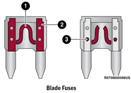
- Fuse Element
- Blade Fuse with a good/functional fuse element
- Blade Fuse with a bad/not functional fuse element (blown fuse)
Underhood Fuses
The Power Distribution Center (PDC) is located on the passenger side of the engine compartment, behind the headlamp. This centre contains cartridges, micro fuses, relays, and circuit breakers. A description of each fuse and component may be stamped on the inside cover, otherwise, the cavity number of each fuse is stamped on the inside cover that corresponds to the following chart.
CAUTION!
When installing the Power Distribution Center cover, it is important to ensure the cover is properly positioned and fully latched. Failure to do so may allow water to get into the Power Distribution Center and possibly result in an electrical system failure.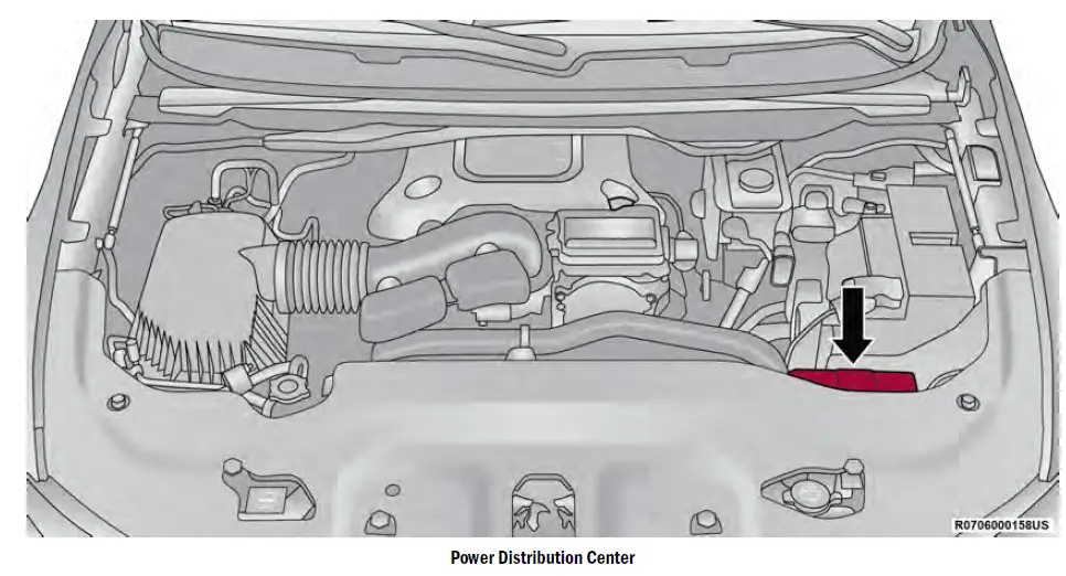
| Cavity | Cartridge Fuse | Micro Fuse | Description |
| * If Equipped | |||
| F01 | – | – | Crank Batt |
| F02 | 80 Amp Gray | – | Elec Pwr Str #1 |
| F03 | 500 Amp Gray | – | Starter |
| F04 | 250 Amp Gray | – | Alternator |
| F05 | 80 Amp Gray | – | Elec Pwr Str #2 |
| F06 | Shunt | – | Aux Battery * |
| F07 | 100 Amp Gray | – | Rad Fan |
| F08 | – | – | Spare |
| F09 | 80 Amp Gray | – | IPDC |
| F10 | 150 Amp Gray | – | RPDC |
| F11 | 150 Amp Gray | – | PCR * |
| F12 | – | – | Spare |
| F13 | 40 Amp Green | – | Starter |
| F14 | – | 10 Amp Red | GNMM */ VPMS * |
| F15 | – | 10 Amp Red | ECM * |
| F16 | – | 15 Amp Blue | Cluster |
| F17A | – | 10 Amp Red | EPS |
| F17B | – | 10 Amp Red | ATMM * |
| F18 | – | – | Spare |
| F19 | 30 Amp Pink | – | BSM #2 Valves * |
| F20 | – | – | Spare |
| F21 | – | – | Spare |
| F22 | – | – | Spare |
| F23A | – | 10 Amp Red | ECM / PPU*/ MGU*/ BSM/ SLM |
| F23B | – | 10 Amp Red | AIR SUSPENSION / ELSD-RR / EPS |
| F24 | – | 20 Amp Blue | XFR Fuel Pump * |
| F25 | – | – | SPARE |
| F26 | 50 Amp Red | – | BSM Motor #2 * |
| F27 | 30 Amp Pink | – | Rear Defroster |
| F28 | – | – | Spare |
| F29 | – | – | Spare |
| F30 | – | – | Spare |
| F31 | 40 Amp Green | – | BCM Feed #3 |
| F32 | – | – | Spare |
| F33 | 30 Amp Pink | – | PWR Side Steps * |
| F34 | – | – | Spare |
| F35 | – | – | Spare |
| F36 | 50 Amp Red | – | BCM Feed #1 |
| F37 | 30 Amp Pink | – | DTCM |
| F38 | 50 Amp Red | – | BCM Feed #2 |
| F39 | – | – | Spare |
| F40 | – | 5 Amp Tan | Batt Snsr #1 |
| F41 | – | 20 Amp Yellow | CADM MAP * |
| F42 | – | – | Spare |
| F43 | – | 10 Amp Red | ECM |
| F44 | – | – | Spare |
| F45 | – | – | Spare |
| F46 | – | 5 Amp Tan | Batt Snsr #2* |
| F47 | – | 10 Amp Red | BPCM |
| F48 | – | 10 Amp Red | CVPAM |
| F49 | – | 30 Amp Green | Air Suspension Valves |
| F50 | – | – | Spare |
| F51 | – | 20 Amp Yellow | Fuel Pmp * / FPCM * |
| F52 | – | – | Spare |
| F53 | – | – | Spare |
| F54 | – | 20 Amp Yellow | Headlamp LT |
| F55 | – | – | Spare |
| F56 | – | – | Spare |
| F57 | – | – | Spare |
| F58 | – | – | Spare |
| F59 | 50 Amp Red | – | Air Suspension |
| F60 | – | – | Spare |
| F61 | – | – | Spare |
| F62 | – | – | Spare |
| F63 | – | 20 Amp Yellow | Camera Washer Frt |
| F64 | – | – | Spare |
| F65 | – | 15 Amp Blue | ACT Grille Shutter / ACT Air Dam / Coolant Valve LCVM * / RATVM |
| F66 | – | 20 Amp Yellow | Horns |
| F67 | – | 10 Amp Red | DTCM / Switchable Engine Mount / BSM #2 |
| F68 | – | 20 Amp Yellow | Headlamp RT |
| F69 | – | – | Spare |
| F70 | – | 20 Amp Yellow | IGN Coil * / IGN Cap */ Fuel Inj */ ISCM * |
| F71 | – | – | Spare |
| F72 | – | – | Spare |
| F73 | – | – | Spare |
| F74 | – | 5 Amp Tan | MGU * |
| F75 | 30 Amp Pink | – | Front Wiper |
| F76 | – | – | Spare |
| F77 | – | 20 Amp Yellow | TCM SBW |
| F78 | – | 20 Amp Yellow | Short Runner Valve / ECM |
| F79 | – | 15 Amp Blue | Fuel INJ * / Surge Solenoid * / Oil Sensor*/ Air Valve * / OBD Bypass*/ O2 Heaters * |
| F80 | 20 Amp Blue | – | ECM |
| F81 | 40 Amp Green | – | BCM Feed #4 |
| F82 | – | – | Spare |
| F83 | – | – | Spare |
| F84 | – | – | Spare |
| F85 | – | 10 Amp Red | PCR * |
| F86 | 50 Amp Red | – | BSM Feed 1 |
| F87 | – | – | Spare |
| F88 | 50 Amp Red | – | BSM Feed 2 |
| F89 | – | – | Spare |
| F90 | – | – | Spare |
| F91 | – | – | Spare |
| F92 | 20 Amp Blue | – | Front De-Icer * |
| F93 | 25 Amp Clear | – | Fuel Pmp * |
| F94 | – | 10 Amp Red | A/C Comp Clutch |
| F95 | – | – | Spare |
| F96 | – | – | Spare |
| F97 | – | – | Spare |
| F98A | – | 15 Amp Blue | Cooling Fan * |
| F98B | – | 15 Amp Blue | Pmp Battery Cooling * |
| F99 | – | – | Spare |
| F100 | – | – | Spare |
| F101 | – | – | Spare |
| F102 | 25 Amp Clear | – | Fuel Pmp * |
| F103 | – | – | Spare |
| F104 | – | – | Spare |
| F105A | – | – | Spare |
| F105B | – | 15 Amp Blue | LTR Coolant Pump |
Interior Power Distribution Center
The Interior Power Distribution Center is located under the driver’s instrument panel. This centre contains cartridges, micro fuses, relays, and circuit breakers.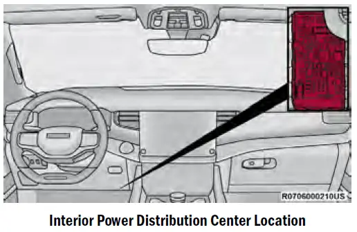
NOTE:
An authorized dealer must service fuses for safety systems.
| Cavity | Cartridge Fuse | Micro Fuse | Description |
| * If Equipped | |||
| F01 | – | – | Spare |
| F02 | – | – | Spare |
| F03 | – | 15 Amp Blue | MOD Seat Heater Frt (Steering Wheel) * |
| F04 | – | 10 Amp Red | Night Vision Module / Driver Monitoring Camera (DMC) |
| F05 | – | – | Spare |
| F06 | – | – | Spare |
| F07 | – | – | Spare |
| F08 | – | 10 Amp Red | Automatic Gearbox Shifter Module (AGSM) / Steering Column Lock / HUD |
| F09 | – | – | Spare |
| F10 | 40 Amp Green | – | HVAC Blower Motor |
| F11 | – | – | Spare |
| F12 | – | 20 Amp Yellow | Assy Cigar Lighter |
| F13 | – | 10 Amp Red | Assy Mirror Inside Rearview / Sunroof Single – Dual Pane / Port UC1 Dual USB RR / Interior Monitoring Camera |
| F14 | – | 10 Amp Red | Refrigerator Box / In-Vehicle Safe * |
| F15A | – | – | Spare |
| F15B | – | – | Spare |
| F16 | – | 10 Amp Red | MOD ORC |
| F17 | – | – | Spare |
| F18 | – | – | Spare |
| F19 | – | – | Spare |
| F20 | – | 10 Amp Red | Overhead Console Assy (OHC) W/Sunshade / Intrusion Module |
| F21 | 30 Amp Pink | – | Trailer Tow Electric Brake – Aftermarket |
| F22 | – | – | Spare |
| F23 | – | – | Spare |
| F24 | – | – | Spare |
| F25 | – | – | Spare |
| F26 | – | – | Spare |
| F27 | – | – | Spare |
| F28 | – | – | Spare |
| F29 | – | – | Spare |
| F30 | – | – | Spare |
| F31 | – | – | Spare |
|
F32 |
– |
10 Amp Red |
MOD ICS Switch Bank / SW Bank Upper / SW EPB / Aux Switch Bank Module (ASBM) / Mod HVAC Cntrl Frt / Humidity Rain Light Sensor (HRLS) |
| F33 | – | 15 Amp Blue | Transfer case SW / SW Bank Lower / Mod ICS Switch Bank Rear / Climate Control Display / Suspension SW * |
| F34 | – | – | Spare |
| F35 | – | 10 Amp Red | IRCAM Heater |
| F36 | – | – | Spare |
| F37 | – | – | Spare |
| F38 | – | – | Spare |
| F39 | – | – | Spare |
| F40 | – | – | Spare |
| F41A | – | – | Spare |
| F41B | – | – | Spare |
| F42A | – | – | Spare |
| F42B | – | 10 Amp Red | MOD HVAC Control Frt |
| F43A | – | – | Spare |
| F43B | – | – | Spare |
| F44 | – | 15 Amp Blue | MOD Cluster CCN / MOD SGW (Cybersecurity) |
| F45 | 30 Amp Pink | – | MOD Inverter 150W |
| F46 | – | – | Spare |
| F47A | – | – | Spare |
| F47B | – | – | Spare |
| F48A | – | – | Spare |
| F48B | – | – | Spare |
| F49 | – | 7.5 Amp Brown | MOD RF HUB / Module Ignition (MD KIN) |
| F50A | – | 10 Amp Red | Port UCI Dual USB Rear |
| F50B | – | 10 Amp Red | Port Diagnostics1&2 |
| F51A | – | – | Spare |
| F51B | – | – | Spare |
| F52 | – | – | Spare |
| F53 | – | 20 Amp Yellow | MOD CMCM (Radio) |
| F54A | – | – | Spare |
| F54B | – | – | Spare |
| F55 | – | – | Spare |
| F56 | – | – | Spare |
| F57 | – | – | Spare |
| F58 | – | – | Spare |
| F59 | – | – | Spare |
| F60 | – | – | Spare |
| F61 | – | – | Spare |
| F62A | – | – | Spare |
| F62B | – | – | Spare |
| F63A | – | 15 Amp Blue | Port UC1 Dual USB Frt / Wireless Charging Pad MOD (WCPM) – High/ Premium Only |
| F63B | – | 15 Amp Blue | Telematics Box Module (TBM) / Mod-DCSD /Mod FPDM |
| F64A | – | 10 Amp Red | MOD ORC |
| F64B | – | 10 Amp Red | Steering Column Control Module (SCCM) |
| F65 | – | 5 Amp Tan | MOD SGW (Cybersecurity) |
| F66 | – | – | Spare |
| CB1 | – | – | Spare |
| CB2 | – | – | Spare |
| CB3 | – | – | Spare |
| CB4 | – | – | Spare |
| CB5 | – | – | Spare |
| CB6 | – | – | Spare |
Rear Power Distribution Center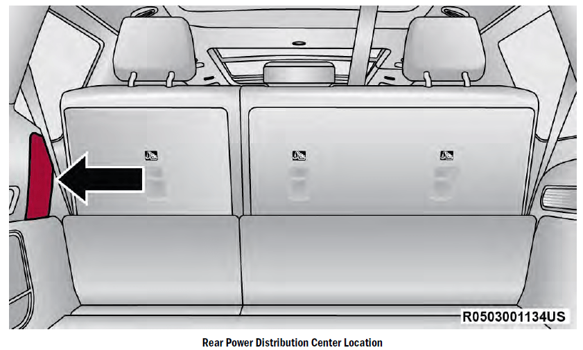
The Rear Power Distribution Center is behind a trim cover of the rear driver’s side quarter panel. This centre contains cartridges, micro fuses, relays, and circuit breakers. The following chart corresponds to the fuses inside.
| Cavity | Cartridge Fuse | Micro Fuse | Description |
| * If Equipped | |||
| F05 | 150 Amp Gray | – | Underhood Power Distribution Center Battery Feed |
| F06 | – | – | Spare |
| F07 | – | – | Spare |
| F08 | – | – | Spare |
| F09 | – | – | Spare |
| F10 | – | – | Spare |
| F11 | – | – | Spare |
| F12 | – | – | Spare |
| F13 | 30 Amp Pink | – | Air Compressor (Tire Inflator) |
| F14 | 25 Amp Clear | – | MTR Sunshade Sunroof |
| F15A | – | – | Spare |
| F15B | – | 10 Amp Red | Hands-Free Liftgate / Rear Window Switches / MOD HVAC Cntrl Rr |
| F16 | – | – | Spare |
| F17 | – | – | Spare |
| F18 | 25 Amp Clear | – | Power Liftgate Module |
| F19A | – | 10 Amp Red | L2+ Driver Alert Lighting Module |
| F19B | – | 10 Amp Red | Animation Lighting RR-LT |
| F20A | – | 15 Amp Blue | Central ASAS Decision Module (CADM) – LO |
| F20B | – | – | Spare |
| F21A | – | – | Spare |
| F21B | – | 10 Amp Red | Sunroof – Dual Pane 2nd & 3rd Row Seat SW-Illumination |
| F22 | – | – | Spare |
| F23 | – | 10 Amp Red | Rear Seat Entertainment (Driver / Passenger) |
| F24 | – | – | Spare |
| F25 | 30 Amp Pink | – | Mod Door MUX Passenger |
| F26 | – | – | Spare |
| F27 | – | – | Spare |
| F28 | 30 Amp Pink | – | MOD Memory / Power Seat (Passenger Frt) |
| F29A | – | 10 Amp Red | Animation Lighting RR-RT |
| F29B | – | 10 Amp Red | Animation Lighting RR-LT |
| F30 | 30 Amp Pink | – | MOD Memory / Power Seat (Driver Frt) |
| F31 | – | – | Spare |
| F32 | – | – | Spare |
| F33 | – | – | Spare |
| F34 | 30 Amp Pink | – | MOD Door MUX Driver |
| F35 | 25 Amp Clear | – | Integrated Trailer Tow Module #2 |
| F36A | – | 10 Amp Red | Intelligent Event Base Lighting Module |
| F36B | – | – | Spare |
| F37 | 25 Amp Clear | – | Integrated Trailer Tow Module #1 |
| F38 | – | – | Spare |
| F39 | – | – | Spare |
| F40 | – | 30 Amp Green | Mod Audio Amplifier #1A |
| F41 | – | – | Spare |
| F42A | – | 10 Amp Red | RSE Video USB Console Frt/Port Media Hub FPDM |
| F42B | – | – | Spare |
| F43 | – | – | Spare |
| F44A | – | 20 Amp Yellow | 12 Volt Power Outlet Cargo Area (Ign) |
| F44B | – | 20 Amp Yellow | 12 Volt Power Outlet Cargo Area (Battery) |
| F45 | – | 20 Amp Yellow | MOD CRSM (Heated Seat RR RT) |
| F46 | 30 Amp Pink | – | Folding Seat Module 3rd Row Feed #1 * |
| F47 | – | – | Spare |
| F48 | – | – | Spare |
| F49 | – | – | Spare |
| F50 | – | 15 Amp Blue | Seat Massage Driver Mod (SSMD) / Seat Massage Passenger Mod (SSMP) * |
| F51 | – | – | Spare |
| F52 | – | 20 Amp Yellow | MOD CRSM (Heat Seat RR LT) * |
| F53 | 30 Amp Pink | – | Electronic Limited Slip Differential (ELSD) Rear #1 * |
| F54 | – | – | Spare |
| F55 | 30 Amp Pink | – | Folding Seat Modules 3rd Row Feed #2 * |
| F56 | – | – | Spare |
| F57 | – | 10 Amp Red | Mod HVAC RR / Mod Occupant Classic / CVPAM / Mod Parktronics / ITCM |
| F58 | – | 15 Amp Blue | 3rd Row Additional USB charge (Only LT – RT) / Port Pwr USB Console UBS (CH Only) |
| F59 | – | 5 Amp Beige | Smart Door Handle Rear Rt |
| F60 | 25 Amp Clear | – | RR_HVAC Blower |
| F61 | – | – | Spare |
| F62 | – | 20 Amp Yellow | Module Seat Heater Frt (Driver) * |
| F63 | 30 Amp Pink | – | Assy Trailer Tow Receptacle B+ |
| F64 | – | 10 Amp Red | Module Smart Phone As Key |
| F65 | – | – | Spare |
| F66 | 20 Amp Blue | – | MOD Door MUX Passenger Rear – Smart Motor |
| F67 | – | 30 Amp Green | MOD Audio Amplifier #1B |
| F68 | – | – | Spare |
| F69 | – | 20 Amp Yellow | L2+ Central ASAS Decision Module (CADM) MID * |
| F70 | – | 10 Amp Red | Video Routing Module (VRM) |
| F71 | – | 5 Amp Beige | Smart Door Handle Driver |
| F72 | – | – | Spare |
| F73 | – | – | Spare |
| F74 | – | – | Spare |
| F75 | – | 5 Amp Beige | Smart Door Handle Rear Lt. |
| F76 | – | 5 Amp Beige | Smart Door Handle Passenger |
| F77 | – | – | Spare |
| F78 | – | – | Spare |
| F79 | – | – | Spare |
| F80 | – | – | Spare |
| F81 | – | 20 Amp Yellow | Module Seat Heater Frt (PASS) * |
| F82 | – | 10 Amp Red | Animation Lighting RR / Air Compressor (Tire Inflator) / Animation Lighting Liftgate Taillamp |
| F83 | – | – | Spare |
| F84 | – | 15 Amp Blue | SNSR_UWB (1-7) |
| F85 | – | – | Spare |
| F86 | – | 15 Amp Blue | Lumbar Support Driver & Passenger SW * |
| F87 | – | – | Spare |
| F88 | 20 Amp Blue | – | MOD Door MUX Driver Rear – Smart Motor |
| CB1 | – | 20 Amp Yellow | Power Outlet RR |
2023 – 2024 Jeep Wagoneer Review, Price, Features And Mileage (Brochure)
How to replace the Fuse of the 2024 Jeep Wagoneer
Replacing a fuse in your 2024 Jeep Wagoneer is a relatively simple task. Here’s a general guide on how to do it:
Materials:
- The new fuse of the correct amperage.
- Fuse puller or needle-nose pliers.
Instructions:
- Locate the Fuse Box: The fuse box in your Jeep Wagoneer is typically located in one of the following places:
- Under the dashboard on the driver’s side.
- Under the hood, near the battery or engine compartment.
- Identify the Fuse: Once you’ve located the fuse box, open the fuse box cover. Inside, you’ll see a diagram or a chart that indicates which fuse corresponds to which electrical component.
- Find the Blown Fuse: Look for the fuse that corresponds to the malfunctioning electrical component. A blown fuse will have a broken metal strip inside. You can visually inspect the fuses or use a multimeter to check for continuity.
- Remove the Blown Fuse: Use a fuse puller tool or a pair of needle-nose pliers to carefully remove the blown fuse. Be gentle to avoid damaging the fuse box or surrounding components.
- Insert the New Fuse: Take a new fuse of the same amperage rating and insert it into the slot vacated by the blown fuse. Make sure it fits snugly.
- Close the Fuse Box Cover: Once you’ve replaced the fuse, close the fuse box cover securely.
- Test the Electrical Component: Turn on the ignition and test the electrical component to ensure it’s functioning properly. If the fuse blows again immediately, there may be a more significant electrical issue that requires professional diagnosis.
- Dispose of the Blown Fuse: Safely dispose of the blown fuse. Do not attempt to reuse a blown fuse as it could lead to further electrical problems.
Tips:
- Always use a fuse with the correct amperage rating to prevent electrical issues or damage to the vehicle.
- If a fuse blows repeatedly, it may indicate an underlying electrical problem and professional assistance may be needed.
FAQs
The fuse box is typically located in the interior cabin of the vehicle. In the 2024 Jeep Wagoneer, it’s usually found beneath the dashboard on the driver’s side or in the engine compartment.
The 2024 Jeep Wagoneer typically has two fuse boxes, one located in the interior cabin and the other in the engine compartment.
The 2024 Jeep Wagoneer typically uses blade-type fuses, also known as ATO or ATC fuses.
Fuses in the 2024 Jeep Wagoneer protect electrical circuits from overloading by breaking the circuit when there’s excessive current flow.
A blown fuse in the 2024 Jeep Wagoneer can be identified by a visibly broken filament inside the fuse or by using a multimeter to check for continuity.
Various accessories such as lights, radio, power windows, power seats, and other electrical components are powered by the fuses in the 2024 Jeep Wagoneer.
The fuse box layout diagram is usually provided in the owner’s manual of the 2024 Jeep Wagoneer.
To access the fuses in the interior fuse box of the 2024 Jeep Wagoneer, you typically need to open the driver’s side door and locate the fuse panel cover on the side of the dashboard.
You typically only need your fingers or a pair of needle-nose pliers to replace a fuse in the 2024 Jeep Wagoneer.
It’s not recommended to use a higher amp fuse as a replacement in the 2024 Jeep Wagoneer, as it may lead to electrical system damage or fire hazards.
Yes, the 2024 Jeep Wagoneer typically comes with a set of spare fuses stored in the fuse box or a designated compartment within the vehicle.
To reset a tripped fuse in the 2024 Jeep Wagoneer, simply replace the blown fuse with a new one of the same rating.
Before replacing the fuses in the 2024 Jeep Wagoneer, it’s important to turn off the ignition and disconnect the battery to prevent electrical shock or damage.
Yes, you can add additional accessories to the fuse box of the 2024 Jeep Wagoneer by using spare fuse slots or by installing a separate fuse block with its wiring.
The maximum amp rating for fuses in the 2024 Jeep Wagoneer varies depending on the electrical component they protect.
Useful Links
View full PDF: 2023 – 2024 Jeep Wagoneer Review, Price, Features And Mileage (Brochure)