
Tata Tigor BS VI 2020 Guidelines
Having a dependable and secure vehicle is essential in today’s fast-paced society, especially during emergencies. A vehicle that goes above and beyond to ensure your safety and dependability, even in the most trying circumstances, is the Tata Tigor BS VI 2020 Emergency Edition. With an emphasis on providing improved safety features and powerful performance, the Tata Tigor BS VI 2020 Emergency Edition is a wonderful addition to the Tata Motors lineup. This special version draws inspiration from the already outstanding Tigor BS VI model, enhancing it while including particular components to address emergency scenarios. The Tata Tigor BS VI 2020 Emergency Edition’s cutting-edge safety technology is one of its most notable features.
Dual front airbags, an ABS with EBD (Electronic Brakeforce Distribution) braking system, corner stability control, and rear parking sensors are just a few of the car’s many safety features. Together, these features make sure that you and your passengers are well-protected in the event of any unforeseen events. Additionally, the Tata Tigor BS VI 2020 Emergency Edition has a strong and dependable engine that ensures peak performance even in adverse conditions. With an engine that complies with BS VI, this automobile offers both efficiency and power, resulting in a smooth and responsive driving experience. The Tigor BS VI 2020 Emergency Edition is designed to tackle any emergency, whether you need to travel a long distance or must maneuver through congested city streets.
Emergency Equipment
You should be familiar with the location of the emergency equipment provided in the vehicle and how to use it.
Do a check of this equipment periodically and make sure that they are in proper working condition and stowed at their locations.
First aid kit
The first aid kit is kept inside the glove box compartment.
The kit contains items that can be used in case of minor injuries only.
NOTE
Examine contents of the first aid kit periodically and replenish consumed or expired items.
Tool kit, tow hook, jack and spare wheel
Tool kit and Jack are accommodated in foam Tool tray located in the rear boot.
NOTE
The tool kit should be properly stored when not in use.
Jack

NOTE
The jack should be used only to change wheels. It is important to read the instructions in this section before attempting to use the jack.
Advance Warning Triangle
An advance warning triangle is kept in the luggage compartment beside the spare wheel.


Use advance warning triangle to warn the approaching traffic in case of vehicle breakdown or during an emergency, where your vehicle could become a potential traffic hazard. Keep the warning triangle at an approximate distance of 50-150 m behind your vehicle in the same lane of traffic. The reflecting side of the triangle should face the oncoming traffic and it should be free from any obstacles. Remove the advance warning triangle carefully from the bag and assemble it. Refer instructions given on the bag.
NOTE
After using the warning triangle tie it firmly and keep it inside the bag to avoid rattling noise.
Hazard Warning Switch
Press the hazard warning switch to activate the hazard warning. All the turn signal lamps will flash simultaneously. To turn OFF, press the switch again.
Use the hazard warning to warn the traffic during emergency parking or when your vehicle could otherwise become a traffic hazard.
The hazard warning lamps can operate even if the ignition is switched off.
SPARE WHEEL REMOVAL PROCESS
- To access the spare wheel, operate live hinge by rotating the part at upside from live hinge lift the carpet up.

- After lifting, hold the carpet to access the spare wheel.

- To remove the spare wheel, unscrew and remove the retaining bolt.

- Remove the Tool tray along with contents
- Following precautions are to be taken when temporary spare wheel is fitted on the vehicle.
WARNING
- Drive the shortest possible distances. The temporary spare wheel should be exchanged for a normal wheel as soon as possible.
- The temporary spare wheel is de-signed for a short period of use only.
“80 km/h” or “50 mph” is the maximum speed you are permit-ted to drive with this tyre.
Never drive faster than 80 km/h (50 mph). Do not accelerate quickly, brake suddenly or drive at high speed through bends.
After fitting the temporary spare wheel, the tyre pressure must be checked as soon as possible.
Recommended tyre pressure is 36 psi (2.5 bar) for temporary spare wheel. - Snow chains cannot be used on the temporary spare wheel.
Never use more than one temporary spare wheel.
Do not drive through an automatic car wash.
Never use a temporary spare tyre if it is damaged or worn down to the tread wear indicators. - The ground clearance of your vehicle may be reduced. Take care when parking next to curb.
The temporary spare should not be installed on the front axle if the vehicle must be driven in snow or on ice.
Do not tow whilst the temporary spare wheel is installed.
NOTE
Your vehicle may exhibit some unusual driving characteristics when fitted with temporary spare wheel.
- IN CASE OF FLAT TYRE
- Reduce vehicle speed gradually, Avoid sudden steering movement or braking.
- Pay attention to the traffic conditions as you do so.
- Switch on the hazard warning lamps.
- If possible, bring the front wheels into the straight-ahead position.
- Stop the vehicle on solid, non-slippery and level ground, as far away as possible from traffic.
- Set the parking brake firmly and shift into “R” (Reverse) gear.
- When the vehicle is in uphill position, shift the gear in first gear.
- Switch off the engine.
- Secure the vehicle against rolling away.
- Keep advance warning triangle at a suitable distance behind the vehicle as an indication of breakdown.
- Close all the doors.
- Use the Jack on level, hard ground. Avoid changing the wheel on uphill and downhill slopes. Chock the wheels, if the deflated wheel needs to be changed on slope / ghat area.
WARNING
If you drive with a flat tyre, there is a risk of the following hazards:
- A flat tyre affects the ability to steer or brake the vehicle.
- You could lose control of the vehicle.
- Continued driving with a flat tyre will permanently damage the tyre and cause excessive heat buildup and possibly a fire. There is a risk of an accident.
Changing Flat Tyre
Loosen the nuts (as indicated) on the wheel in diagonal sequence. Do not un-screw the nuts completely before raising the vehicle using the jack.
Wheel nut removal
NOTE
- The jack is designed only to raise and hold the vehicle for a short time while a wheel is being changed. It is not suited for performing maintenance work under the vehicle.
- Use the jack on level, hard ground. Avoid changing the wheel on uphill and downhill slopes. Chock the wheels, if the deflated wheel needs to be changed on slope / ghat area.
- Reduce vehicle speed gradually, avoid sudden steering movement or braking.
Pay attention to the traffic conditions as you do so. - Switch on the Hazard warning lamps.
- Stop the vehicle on solid, non-slippery and level ground, as far away as possible from traffic.
Before raising the vehicle, secure it from rolling away by applying the parking brake. - Do not use wooden blocks or similar objects as a jack underlay.
Do not place your hands and feet or lie under the raised vehicle when it is supported by a jack. - Do not run the engine when the vehicle is supported by the jack and never allow passengers to remain in the vehicle.
- Do not open or close a door or the tailgate when the vehicle is raised.
- Use the jack on level, hard ground. Avoid changing the wheel on uphill and downhill slopes. Chock the wheels, if the deflated wheel needs to be changed on slope /ghat area.
- If possible, bring the front wheels in to the straight-ahead position.
- Secure the vehicle against rolling away.
- Set the parking brake firmly and shift into “R” (Reverse gear) on level ground and while vehicle is in a downhill position.
- When the vehicle is in uphill position, shift the gear in first gear.
Assemble the Jack handle and wheel spanner (as shown in fig.)
Position the jack vertically and raise it by turning the jack handle clockwise until the jack sits completely on the specified point and the base of the jack lies evenly on the ground.
The jack up points are indicated by cutouts on the front and rear.
Jack up point location on vehicle
Jack up point location

Front Jacking location

Rear jacking Location
WARNING
If you do not position the jack correctly at the appropriate jacking point of the vehicle, the jack could tip over with the vehicle raised.
There is a risk of injury. Also jack can be damaged.
Continue to raise the jack slowly and smoothly until the tyre clears the ground. Do not raise the vehicle more than required.
Lifting the front wheel using jack
Lifting the rear wheel using jack
Remove wheel nuts with the help of wheel spanner and take out flat tyre.
NOTE
Do not place wheel nuts in sand or on a dirty surface. Do not apply oil or grease on it.
Roll the spare wheel into position and align the holes in the wheel studs.
- Tighten each nut by hand until the wheel is securely seated on the hub.
- Lower the jack completely then tighten the wheel nuts one by one using wheel spanner.
- Press fit the wheel cover back (if fitted).
- Restore all the tools and jack at their respective locations.
- Place the flat tyre at spare wheel location.
NOTE
- Do a check and correct the tyre pressure and wheel nuts tight-ness of the changed wheel at nearest authorized service station. Get the flat tyre repaired at the earliest
- Place the jack only at recommended jacking locations.
Jump-starting your car
Use only a battery of same rating & capacity to jump start your vehicle. Position the booster battery close to your vehicle so that the jump leads will reach both batteries.
When using a battery of another vehicle, do not let the vehicles touch. Apply the parking brake firmly and keep the gear-shift lever in neutral.
Turn off all vehicle accessories, except those necessary for safety like hazard warning lamps.
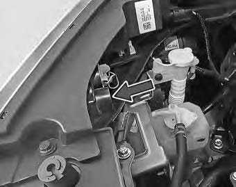
If your vehicle is equipped with Battery Sensor, then do not connect your jump start cable lead directly on the Sensor surface. Connect only on the negative cable surface as shown on the image. After jump start event, IAC function will be restored only when the Vehicle is parked in idle for 3-4 Hours.

Make jump lead connections as follows:
-
- Connect one end of the first jump lead to the positive (+) terminal of the discharged battery.
- Connect the other end to the positive (+) terminal of the booster battery.
- Connect one end of the second jump lead to the negative (–) terminal of the booster battery.
- Make the final connection (other end of the negative terminal) to an un-painted, heavy metal part (i.e. engine mounting stud/nut) of the vehicle of discharged battery.

- Start the engine of the vehicle with the discharged battery.
- Before disconnecting the jumper cables, let the engine run for several minutes.
- If the booster battery you are using is fitted to another vehicle, start the engine of the vehicle with the booster battery. Run the engine at moderate speed.
- Remove the jump leads in the exact reverse order in which you connected them.
NOTE
Do not disconnect the discharged battery from the vehicle.
WARNING
- Do not connect the jump lead directly to the negative (–) terminal of the discharged battery. This may lead to an explosion.
Do not allow battery electrolyte to come in contact with eyes, skin, fabrics or painted surfaces. The fluid contains acid which can cause injury and severe damage. Wear protective apparel. Do not inhale any battery gases. Keep children away from batteries. In case if battery acid comes in con-tact with the skin, wash it off immediately with water and seek medical attention. - During charging and jump-starting, explosive gases can escape from the battery. There is a risk of an explosion. Particularly avoid fire, open flames, creating sparks and smoking. Make sure that there is sufficient ventilation while charging and jump-starting. Do not lean over the battery.
Make sure that the positive terminal of a connected battery does not come into contact with vehicle parts. Never place metal objects or tools on a battery.
It is important that you observe the described order of the battery terminals when connecting and disconnecting a battery. If you are in doubt, seek assistance from qualified specialist work-shop.
Do not connect or disconnect the battery terminals while the engine is running.
NOTE
If your vehicle is equipped with a battery sensor, connect the jump start leads on output terminal of battery sensor. Do not connect the jump start leads on sensor surface or battery terminal. This will result of function loss of battery sensor.
Towing

When towing a breakdown vehicle, certain precautions and procedures must be taken to prevent damage to the vehicle and/or components. Failure to use standard towing precautionary measures when lifting or towing a breakdown vehicle could result in an unsafe operating condition.
To correctly tow and prevent accidental damage to your vehicle, take help of a TATA MOTORS authorized dealer or a commercial tow-truck service.
NOTE
Make sure that the parking brake is released; vehicle is in neutral and the steering wheel is unlocked. The power steering functions only when engine is running. Hence, during towing the steering efforts will be more.
WARNING
- Do not get under your vehicle after it has been lifted by a tow truck.
For towing a vehicle, the best way is to use a wrecker. Alternatively, use a rigid tow bar.
Switch ‘ON’ the hazard warning indicators of both vehicles to warn other road users.
Limit the speed to 20-30 kmph.
In case of brake failure, use the parking brake to control the vehicle. - Fasten the tow rope or tow bar at the towing eyes. Otherwise, the vehicle could be damaged.
When towing, pull away slowly and smoothly. If the tractive power is too high, the vehicles could be damaged.
Tow hook fitment
- Open the tailgate and remove tow hook from the tool kit.

- Open the tow hook cover provided on the front bumper by pressing it at the bottom part and simultaneously pulling it at the top (as shown in fig).

- Screw in and tighten the tow hook in clockwise direction.
After towing, remove the towing hook and press fit the cover properly.
Place the towing hook in the vehicle tool kit.
Recommended towing
In case of break down, we recommend that your vehicle be towed with the driving wheels off the ground or place the vehicle on a flatbed truck as shown.
WARNING
- Do not tow your vehicle with the front wheels on the ground or four wheels on the ground (for-ward or backward), as this may cause serious damage to the transmission.
When towing with the rear wheels on the ground or on towing dollies, place the ignition switch in the ‘ACC’ or ‘ON’ position, and secure the steering wheel in the straight-ahead position with a rope or similar device.

Towing instructions (AMT):
A) Where vehicle can be shifted in neutral condition
- Shift the gear lever into neutral.
Turn the ignition key to the “ACC” position to unlock the steering wheel.
Release the parking brake.
NOTE
After shifting the AMT gearshift lever to the “N” position, always check the gear position indicator in the instrument cluster shows the “N” position to make sure that the transaxle is disengaged.
If the transaxle cannot be put in neutral, turn the key from the “OFF” to the “ON” position, and move the AMT gearshift lever from “N” to “A”, “M” or “R”, then back to “N” again. Then turn the key from the “ON” to the “OFF” position. These procedures may help to put the transaxle in neutral.
If the transaxle still cannot be put in neutral, you cannot tow the vehicle without lifting vehicle from rear side.
B) Where vehicle cannot be shifted in neutral condition:
- Secure the rear wheels on a towing lift and the front wheels on the towing trolley.
Apply the parking brake.
WARNING
A safety chain/belt for tightening the wheels with lift should always be used when you tow your vehicle.

NOTE
Always unlock the steering wheel be-fore towing.
Fuses
Your vehicle has fuse boxes at three lo-cations.
The vehicles electrical circuits have fuses to protect the wiring from short circuits or sustained overload.

- Battery Mounted Fuse Box.
- Engine Compartment Fuse Box.
- Cabin Compartment Fuse Box.
FUSES
Your vehicle has fuse boxes at three locations.
The vehicles electrical circuits have fuses to protect the wiring from short circuits or sustained overload.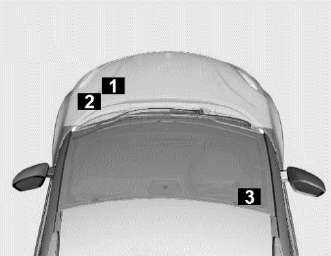
- Battery Mounted Fuse Box.
- Engine Compartment Fuse Box.
- Cabin Compartment Fuse Box.
Checking And Replacing Fuses
If any electrical unit in your vehicle is not functioning, check the fuses first.
Please follow the steps below that will guide you to check and replace them.
- Apply parking brake
- Switch off all electrical accessories.
- Turn the ignition key to the ‘LOCK’ position.
- In the fuse box, identify the defective fuse from its melted wire.

- Remove the defective fuse by “fuse puller”. The fuse puller and spare fuses are provided in the engine compartment fuse box.

- Defective fuses must be replaced with fuses of same rating, which you can recognize by color and value.
NOTE
Always make sure that the spare fuses are added.
- Make sure that all other fuses are pressed firmly in position.
- If a newly inserted fuse also blows, have the cause traced and rectified at nearest TATA MOTORS Authorized Dealer/Service Center immediately.
WARNING
If you manipulate or bridge a faulty fuse or if you replace it with a fuse with higher amperage, the electric cables could be overloaded. This could result in a fire. There is a risk of an accident and injury.
Always replace faulty fuses with the specified new fuses having the correct amperage.
Battery Mounted Fuse Box

PF1 STARTER MOTOR
WARNING
If Fuse box cover is removed for any reason, it should be refitted properly in its original position.
Fuses – Engine Compartment (Petrol)


| Fuse No. | Function | Fuse Rating |
| 1 | INTERIOR F/B 2 IGNITION | 60A |
| 2 | ABS | 40A |
| 3 | – | – |
| 4 | COOLING FAN / PWM | 40A |
| 5 | EPAS | 60A |
| 6 | – | – |
| 7 | INTERIOR F/B 1 BATTERY | 60A |
| 8 | UNDER BON- NET F/R BOX | 30A |
| 9 | – | – |
| 10 | IGNITION LOAD | 60A |
| 11 | TCU | 30A |
| 12 | COMPRESSOR | 10A |
| 13 | STARTER SOLENOID | 25A |
| 14 | ABS ECU | 25A |
| 15 | H/L LOW | 15A |
| 16 | HORN | 15A |
| 17 | TCU | 10A |
| 18 | EMS BATTERY | 10A |
| 19 | H/L HIGH | 15A |
| 20 | FUEL PUMP | 15A |
| 21 | BRAKE LAMP | 10A |
| 22 | RELAY COIL | 5A |
| 23 | – | – |
| 24 | FRONT WIPER MOTOR | 20A |
| 25 | ABS | 5A |
| 26 | – | – |
| 27 | TCU | 10A |
| 28 | REVERSE & BRAKE LAMP | 10A |
| 29 | REAR WIPER | 10A |
| 30 | EMS ECU SUPPLY | 20A |
| 31 | EMS SENSORS & RELAYS | 15A |
| 32 | INJECTORS (PETROL) | 10A |
| 33 | STARTER RE- LAY F/B | 5A |
| 34 | FRONT FOG | 10A |
| 35 | ||
| 36 | IBS | 5A |
Cabin Compartment Fuse Box
Cover Removal Procedure
- Fuse box is located inside the cover below steering column. To access the fuse box, remove cover as per procedure given below.

- To remove the cover, gently pull the cover from upper side
Re-fitment Procedure
Align bottom lugs and push upper part with respective slots on dashboard and press the cover firmly.
Fuses – Cabin Compartment Cabin compartment fuse box
Note: This is for reference only. Check sticker provided on vehicle.
| Fuse Function Fuse
No. Rating |
||
| 1 | RESTRAINT CONTROL MOD- ULE | 10A |
| 2 | ACC CON.2/OBD | 15A |
|
3 |
INTELLIGENT TRANSPOR-
TAION SYSTEM |
15A |
| 4 | BCM | 15A |
| 5 | REV LAMP & BRK SW | 10A |
| 6 | MIRROR AD- JUST MOTOR | 5A |
| 7 | BCM | 15A |
| 8 | INSTRUMENT CLUSTER | 5A |
| 9 | BCM | 15A |
| 10 | KEY IN/PEPS/BLOWE R RELAY | 5A |
| 11 | EPAS | 5A |
| 12 | ACC FUSE
/POWER SKT |
5A/15A |
| 13 | BLOWER MO- TOR | 30A |
| 14 | CDL / ACCES- SORY CONN.1 | 15A |
| 15 | PDC IGN SUP- PLY | 5A |
| 16 | RELAY COILS/PEPS | 5A/10A |
| 17 | TAILGATE LATCH | 10A |
| 18 | HVAC/FATC | 10A |
| 19 | HEATED REAR SCREEN | 25A |
| 20 | MODULE KL.15 I/P | 10A |
| 21 | POWER SKT CONSOLE | 15A |
| 22 | TRANSIT/INFO- TAINMENT | 15A |
Bulb Specification
| SN | Description | Rating | Type | Qty. |
| 1 | HIGH BEAM + LOW BEAM (option I) | 12V, 55/60W | H19 | 2 |
|
2 |
HIGH BEAM (Option II) | 12V, 55W | H7 | 2 |
| LOW BEAM (Option II) | 12V,55W | H11 | 2 | |
| 3 | TURN SIGNAL FRONT | 12V, 21W | PY21W | 2 |
| 4 | FOG LAMP FRONT | 12V, 19W | H16 | 2 |
| 5 | STOP + POSITION LAMP REAR | 12V, 21/5W | P21/5W | 2 |
| 6 | POSITION LAMP FRONT | 12V, 5W | W5W | 2 |
| 7 | TURN SIGNAL REAR | 12V, 21W | PY21W | 2 |
| 8 | REVERSE LAMP | 12V, 16W | W16W | 2 |
| 9 | REAR REGISTRATION PLATE LAMP | 12V, 5W | W5W | 2 |
| 10 | SIDE REPEATER LAMP | 12V, 5W | WY5W | 2 |
| 11 | ROOF LAMP | 12V | LED | 1 |
| 12 | HIGH MOUNTED STOP LAMP | 12V, 5W | W5W | 5 |
| 13 | POSITION LAMP REAR | 12V,5W | W5W | 2 |
Head Lamp Bulb Replacements
WARNING
Do not run the engine when you change bulbs.
If the engine has been running just prior to replacing bulbs in the head-light housing, please keep in mind that components in the engine compartment will be hot.
NOTE
Your vehicle’s headlamps have replaceable halogen bulbs.
Replacing The Low Beam Bulb
-
- Lift the bonnet to access the bulbs.
- Lift the bonnet to access the bulbs.
- Remove the Bulb Access cover by rotating as per the direction arrow shown on the cover.
- Press the pin and pull the connector from the bulb.
- To free the headlamp bulb from the socket, press and swing the retaining spring and pull it straight back.
- Pull out the bulb from the socket.
- Insert the new bulb (without touching the glass) into the socket.
- Move the retaining spring up and push it slightly until it locks properly.
- Refit the connector in to the Bulb & rotate the Bulb Access Cover as per the direction arrow shown on the cover.
WARNING
It is dangerous if a halogen bulb breaks. These bulbs contain pressurized gas and if broken, will explode causing serious in-jury by the flying glass.
Halogen bulbs can break if the glass portion is touched with bare hands, body oil could cause the bulb to heat unevenly and explode when lit.
Never touch the glass portion of the bulb with your bare hands and al-ways wear eye protection when handling or working around halogen bulbs. Always keep halogen bulbs out of the reach of children.
24 X 7 ROAD ASSISTANCE
Dear Customer,
It is our responsibility and our endeavor to ensure that you have our complete service backup if ever, wherever and whenever you need the same. When you have a road network that spans wide area, the probability of a breakdown happening within hailing distance of a TATA MOTORS Authorized Workshop is very low.
It is precisely for this reason, we have tied up with TVS AA, who will provide break-down assistance including towing to the nearest TATA MOTORS Authorized Work-shop through their Authorized Service Providers (ASP).
The 24X7 On Road Assistance Program shall be automatically available to your vehicle for the duration of the Warranty period. The program shall also be available if you avail the same post warranty.
Response Time
For The On Road Assistance Program
| Within City Limits | 60 minutes |
| On State or National Highways | 90 minutes |
| Ghat Roads and other places | 120 minutes +/- |
(The response time will depend on the location, terrain, traffic density and the time of the day.)
Standard Procedure When Calling For On-Road Assistance In Case Of A Breakdown
- Dial the toll free helpline number –1800 209 8282
- Identify your vehicle with the Vehicle chassis number that is available in the Owner’s Manual.
- Explain your exact location with landmarks and tell us about the problem you face with the vehicle.
- Park your vehicle on the edge of the road, open the bonnet and put on the hazard warning signal.
- Place the advance warning triangle supplied with the vehicle approx. 3 m from the vehicle in the direction of on-coming traffic.

Coverage under 24 X 7 on Road Assistance Program
The 24×7 On Road Assistance Pro-gram Service covers the following services on your vehicle during the warranty period.
- Wheel change through spare wheel.
Arrangement of fuel. (Fuel cost will be chargeable at actual cost).
Re-opening the vehicle in cases of key lock out.
Rectification of electrical problems related to battery, fuses etc.
On spot repairs for complaints repairable at site. ^
Vehicle-to-vehicle towing or winching & towing for non-accident cases up to the nearest TATA MOTORS Authorized Dealer/Service Center. Towing charges at actual cost beyond the same to be paid to the ASP in cash.(Any ferry or toll charges levied in relation to the vehicle being towed to be paid by the customers in actuals in cash).
For accident cases, towing charges to be borne by the customer.
II. The 24×7 On Road Assistance Program coverage on availing the 24X7 pol-icy, post-warranty is upto a maximum of 6 instance of assistance in one year for both the plans- Basic and Premium. In the premium plan, this includes 2 instances of towing up to the nearest TATA MOTORS Authorized Dealer/Service Center.
Exclusions
24 X 7 On Road Assistance Program does not apply to Cost of parts consumables and labor for such repairs not covered under warranty*. These charges are to be settled with ASP in cash.
Toll or ferry charges paid by ASP in reaching to the breakdown site to be settled with ASP in actuals in cash.
Cases involving accident, fire, theft, vandalism, riots, lightening, earthquake, windstorms, hail, tsunamis, unusual weather conditions, other acts of God, flood, etc.
Vehicles that are unattended, unregistered, impounded or abandoned.
Breakdown/defects caused by misuse, abuse, negligence, alterations or modifications made to the vehicle.
- Lack of maintenance as per the maintenance schedule as detailed in the owner’s manual.
Cases involving racing, rallies, vehicle testing or practice for such events.
Disclaimer
- The Service is not available in Lakshadweep.
The reach time is indicative & the actual reach time will be conveyed by the call center at the time of the break-down call.
The reach time can vary depending on the traffic density & time of the day.
The reach time indicated does not account for delays due to but not limited to acts of God, laws, rules & regulations for time being in force, orders of statutory or Govt. authorities, industrial disputes, inclement weather, heavy down pour, floods, storms, natural calamities, road blocks due to accidents, general strife and law & order conditions viz. fire, arson, riots, strikes, terrorist attacks, war etc.
On spot repairs at the breakdown site shall depend on nature of the complaints & will be as per the discretion of the ASP.
The decision for free-of-charge repairs will be as per the warranty policy & procedures of TATA MOTORS LTD. and as per the interpretation of the same by ASP. You will be duly informed by the ASP & call center for the change applicable if any.
- All charges wherever applicable need to be settled directly with the ASP.
Exclusion of Liabilities
It is understood that TATA MOTORS shall be under no liability whatsoever in respect of any loss or damage arising directly or indirectly out of any de-lay in or non-delivery of, defect/deficiency in service/parts provided by ASP.
- In case vehicle cannot be repaired on-site, customers are advised to use the towing facility for taking their vehicle to the nearest TATA MOTORS authorized workshop only. In no condition shall the vehicle be towed to any unauthorized workshop. TATA MOTORS will not be responsible for any repairs carried out in such an unauthorized workshop.
Customer are advised to take acknowledgment from the ASP for the list of accessories/extra fittings and other belongings in the vehicle as well as the current condition related to dents/scratches breakages of parts/fitments of the vehicle at the time of ASP taking possession of the vehicle & to verify these items when delivery is taken back by them, Claim for loss of or damage to items, if any should be taken up with ASP directly. TATA MOTORS shall not be responsible for any such claims, damages/loss or any deficiency of service of the ASP. - Vehicles will be handled, repaired & towed as per the customer’s risk & TATA MOTORS shall not be liable for any damages/claims as a result of the same.
Services entitled to the customers can be refused or cancelled on account of abusive behavior, fraudulent representation, malicious intent and refusal to pay the charges for any charges related services and spare parts during service or on previous occasions on part of the customer.
On site repairs may be temporary in nature. The completion of repairs does not certify the roadworthiness of the vehicle. The customer is advised to ensure temporary repairs carried out onsite is followed by permanent repairs at a TATA MOTORS Authorised Dealer/Service Center at the earliest. Terms and conditions and service coverage, exclusions etc. are subject to change without notice.
FAQs
In the event of a breakdown, pull over to the side of the road, activate your hazard lights, and contact the roadside assistance number provided by Tata Motors
Refer to the owner’s manual of the vehicle for specific instructions on how to change a punctured tire. Make sure the trunk contains the necessary tools and a spare tire.
Stop immediately and shut off your ignition. Allow it to cool before examining the level of coolant. If necessary, add coolant, but never remove the radiator cover while the engine is hot.
Connect jumper cables to the battery of another vehicle using the correct jump-starting procedures. Refer to the owner’s manual for detailed instructions.
Contact a roadside assistance service or travel to the nearest gas station to obtain fuel in a suitable container if you run out of gas.
Try to move the steering wheel gently while turning the key. Contact a professional locksmith or Tata Motors’ roadside assistance if this does not work.
To release your vehicle, contact a locksmith or roadside assistance service.
Ensure the safety of all occupants, summon for medical assistance if necessary, and notify the authorities of the accident. Follow the appropriate legal procedures and notify your insurer.
Shift into lower gears, apply the handbrake (if necessary), and attempt to come to a safe halt. Immediately have your brakes inspected and serviced.
Pull the safety pin, aim the nozzle at the fire’s base, and squeeze the handle to discharge the extinguishing agent. Side to side until the fire is extinguished. Ensure you have received appropriate fire extinguisher training.
Remain calm, promptly open the window or sunroof (if available), and escape through it. If you are unable to open a window, wait until the vehicle fills with water before opening the door.
Refer to your owner’s manual for specific warning light meanings. Pull over, turn off the engine, and contact a service center or roadside assistance if a critical issue is detected.
Keep a first aid kit in your vehicle and follow fundamental first aid procedures, such as stopping bleeding, administering CPR, and stabilizing injuries until medical assistance arrives.
If no other options are available, manually unlock the doors, utilize emergency escape tools, or shatter the windows to escape.
Perform routine vehicle inspections, maintain an emergency kit (including a flashlight, first aid supplies, and basic tools), and have readily available contact information for roadside assistance.
Useful Link
Download Link: Owner’s Manuals | Tata Motors Service
View Full Manual: Tata Tigor BS VI 2020 User Manual | Auto User Guide