
Dodge Ram Pickup 2023 Service and Maintenance User Manual
Service and Maintenance
CAUTION!
Failure to perform the required maintenance items may result in damage to the vehicle.
Your vehicle is equipped with an engine oil change indicator system. This system will alert you when it is time to change your engine oil by displaying the words
“Oil Change Due” in your instrument cluster display. The engine oil change indicator system is duty cycle based, which means the engine oil change interval may fluctuate depending on your personal driving style. Failure to change the engine oil per the maintenance schedule can result in internal engine damage.
An authorized dealer will reset the oil change indicator message after completing the scheduled oil change. If a scheduled oil change is performed by someone other than an authorized dealer, the message can be reset by referring to the steps described under instrument cluster display page 104.
For gasoline engines, under no circumstances should oil change intervals exceed 8,000 miles (13,000 km),
12 months or 350 hours of engine run time, whichever comes first. The 350 hours of engine run or idle time is generally only a concern for fleet customers.
For diesel engines, under no circumstances should oil change intervals exceed 15,000 miles (24,000 km) or 12 months, whichever comes first or sooner if prompted by the oil change indicator system.
NOTE:
- It is recommended that every 3,000 miles (4,800 km), check the engine oil level at least 30 minutes after a fully warmed engine is shut off. Checking the oil level while the vehicle is on level ground will improve the accuracy of the oil level reading. Add oil only when the level is at or below the ADD or MIN mark.
- Severe service (high ambient temperature, short trips, heavy loading, trailer towing, off-road, or law enforcement use) may reduce oil change intervals.
For Diesel Engines, configured with optional B20 capability are operated with greater than 5% levels of biodiesel, the oil change interval must not exceed 12,500 miles (20,000 km) or 400 hours, whichever comes first under any circumstances. See the Fuel Requirements section for more information regarding operation with biodiesel blend (B6-B20) fuel meeting ASTM specification D-7467.
Perform Service Indicator — Diesel Engine
Your vehicle will require emissions maintenance at a set interval. To help remind you when this maintenance is due, the instrument cluster will display “Perform Service”. When the “Perform Service” message is displayed on the instrument cluster it is necessary to have the emissions maintenance performed. Emissions maintenance may include replacing the Closed Crankcase Ventilation (CCV) filter element. The procedure for clearing and resetting the “Perform Service” indicator message is located in the appropriate Service Information.
Once A Month Or Before A Long Trip:
- Check engine oil level.
- Rotate tires at the first sign of irregular wear, even if it occurs before the oil indicator system turns on.
- Check windshield washer fluid level.
- Check the fluid levels of the coolant reservoir, brake master cylinder and power steering and fill as needed.
- Check function of all interior and exterior lights.
At Each Oil Change
- Change the engine oil and filter.
- Inspect the exhaust system.
- Check tire pressure and look for unusual wear or damage. Rotate tires at the first sign of irregular wear, even if it occurs before the oil indicator system turns on.
- Inspect the batteries, and clean and tighten the terminals as required.
- Inspect the CV/Universal joints.
- Inspect brake pads, shoes, rotors, drums, hoses and parking brake.
- Inspect engine cooling system protection and hoses.
- Inspect front end, and lubricate — If equipped with serviceable fittings.
- Inspect engine air cleaner filter if using in dusty or off-road conditions. If required, replace engine air cleaner filter.
- Inspect and replace the Evaporative System Fresh Air Filter as necessary, replacement may be more frequent if vehicle is operated in extreme dusty conditions.
Inspection and service should also be performed anytime a malfunction is observed or suspected. Retain all receipts.
NOTE: Using white lithium grease, lubricate the door hinge pivot joints twice a year to prevent premature wear.
MAINTENANCE PLAN — GASOLINE ENGINE
| Mileage Or Time Passed (Whichever Comes First) | 20,000 | 30,000 | 40,000 | 50,000 | 60,000 | 70,000 | 80,000 | 90,000 | 100,000 | 110,000 | 120,000 | 130,000 | 140,000 | 150,000 |
| Or Years: | 2 | 3 | 4 | 5 | 6 | 7 | 8 | 9 | 10 | 11 | 12 | 13 | 14 | 15 |
|
Or Kilometers: |
32,000 | 48,000 | 64,000 | 80,000 | 96,000 | 112,000 | 128,000 | 144,000 | 160,000 | 176,000 | 192,000 | 208,000 | 224,000 | 240,000 |
| Change engine oil. | Under no circumstances should oil change intervals exceed 8,000 miles (13,000 km), 12 months or 350 hours of engine run time, whichever comes first. | |||||||||||||
| Additional Inspections | ||||||||||||||
| Rotate the tires. | X | X | X | X | X | X | X | X | X | X | X | X | X | X |
| Inspect the CV/Universal joints. | X | X | X | X | X | X | X | X | X | X | X | X | X | X |
| Inspect front suspension, tie rod ends, and replace if necessary. | X | X | X | X | X | X | X | |||||||
| Inspect the front and rear axle surfaces. If gear oil leakage is suspected, check the fluid level. If using your vehicle for police, taxi, fleet, off-road or frequent trailer towing, change axle fluid. | X | X | X | X | X | X | X | |||||||
| Inspect the brake linings, replace as necessary. | X | X | X | X | X | X | X | |||||||
| Adjust parking brake as necessary. | X | X | X | X | X | X | X | |||||||
| Inspect transfer case fluid. | X | X | X | |||||||||||
| Additional Maintenance | ||||||||||||||
| Replace the cabin air filter. | To be replaced every 12,000 miles (19,000 km). | |||||||||||||
| Replace the engine air cleaner filter. | X | X | X | X | X | |||||||||
- The spark plug change interval is mileage based only, yearly intervals do not apply.
WARNING!
- You can be badly injured working on or around a motor vehicle. Do only service work for which you have the knowledge and the right equipment. If you have any doubt about your ability to perform a service job, take your vehicle to a competent mechanic.
- Failure to properly inspect and maintain your vehicle could result in a component malfunction and affect vehicle handling and performance. This could cause an accident.
| Mileage Or Time Passed (Whichever Comes First) | 20,000 | 30,000 | 40,000 | 50,000 | 60,000 | 70,000 | 80,000 | 90,000 | 100,000 | 110,000 | 120,000 | 130,000 | 140,000 | 150,000 |
| Or Years: | 2 | 3 | 4 | 5 | 6 | 7 | 8 | 9 | 10 | 11 | 12 | 13 | 14 | 15 |
| Or Kilometers: | 32,000 | 48,000 | 64,000 | 80,000 | 96,000 | 112,000 | 128,000 | 144,000 | 160,000 | 176,000 | 192,000 | 208,000 | 224,000 | 240,000 |
| Replace spark plugs. 1 | X | |||||||||||||
| Flush and replace the engine coolant at 10 years or 150,000 miles (240,000 km) whichever comes first. | X | X | ||||||||||||
| Inspect the transfer case fluid, change for any of the following: police, taxi, fleet, or frequent trailer towing. | X | X | ||||||||||||
| Change the transfer case fluid. | X | |||||||||||||
| Inspect and replace PCV valve if necessary. | X |
MAINTENANCE PLAN — DIESEL ENGINE
| Mileage Or Time Passed (Whichever Comes First): | 7,500 | 15,000 | 22,500 | 30,000 | 37,500 | 45,000 | 52,500 | 60,000 | 67,500 | 75,000 | 82,500 | 90,000 | 97,500 | 105,000 | 112,500 | 120,000 | 127,500 | 135,000 | 142,500 | 150,000 |
| Or Months: | 6 | 12 | 18 | 24 | 30 | 36 | 42 | 48 | 54 | 60 | 66 | 72 | 78 | 84 | 90 | 96 | 102 | 108 | 114 | 120 |
| Or Kilometers: | 12,000 | 24,000 | 36,000 | 48,000 | 60,000 | 72,000 | 84,000 | 96,000 | 108,000 | 120,000 | 132,000 | 144,000 | 156,000 | 168,000 | 180,000 | 192,000 | 204,000 | 216,000 | 228,000 | 240,000 |
| Change engine oil every 15,000 miles (24,000 km) or 12 months or 500 Hours or sooner if prompted by the oil change indicator system, whichever comes first. | X | X | X | X | X | X | X | X | X | X | ||||||||||
| Additional Inspections | ||||||||||||||||||||
| Check the Diesel Exhaust Fluid (DEF) tank, refill if necessary. | X | X | X | X | X | X | X | X | X | X | X | X | X | X | X | X | X | X | X | X |
| Rotate the tires. | X | X | X | X | X | X | X | X | X | X | X | X | X | X | X | X | X | X | X | X |
| Inspect front end, and lubricate — If equipped with serviceable fittings. | X | X | X | X | X | X | X | X | X | X | X | X | X | X | X | X | X | X | X | X |
| Inspect engine air cleaner filter, replace if necessary. 1 | X | X | X | X | X | X | X | X | X | X | ||||||||||
| Inspect the CV/Universal joints. | X | X | X | X | X | X | X | X | X | X | X | X | X | X | X | X | X | X | X | X |
| Mileage Or Time Passed (Whichever Comes First): | 7,500 | 15,000 | 22,500 | 30,000 | 37,500 | 45,000 | 52,500 | 60,000 | 67,500 | 75,000 | 82,500 | 90,000 | 97,500 | 105,000 | 112,500 | 120,000 | 127,500 | 135,000 | 142,500 | 150,000 |
| Or Months: | 6 | 12 | 18 | 24 | 30 | 36 | 42 | 48 | 54 | 60 | 66 | 72 | 78 | 84 | 90 | 96 | 102 | 108 | 114 | 120 |
| Or Kilometers: | 12,000 | 24,000 | 36,000 | 48,000 | 60,000 | 72,000 | 84,000 | 96,000 | 108,000 | 120,000 | 132,000 | 144,000 | 156,000 | 168,000 | 180,000 | 192,000 | 204,000 | 216,000 | 228,000 | 240,000 |
| Inspect the front suspension, tie rod ends and boot seals for cracks or leaks and all parts for damage, wear, improper looseness or end play; replace if necessary. |
X |
X |
X |
X |
X |
X |
X |
X |
X |
X |
||||||||||
| Inspect the brake linings. | X | X | X | X | X | X | ||||||||||||||
| Inspect and adjust parking brake. | X | X | X | X | X | X | ||||||||||||||
| Inspect drive belt; replace as necessary. | X | X | X | X | X | X | ||||||||||||||
| Inspect wheel bearings. | X | X | X | X | X | |||||||||||||||
| Additional Maintenance | ||||||||||||||||||||
| Replace the cabin air filter. | To be replaced every 12,000 miles (19,000 km). | |||||||||||||||||||
| Replace the engine fuel filter. | X | X | X | X | X | X | X | X | X | X | ||||||||||
| Replace the chassis mounted fuel filter. | X | X | X | X | X | X | X | X | X | X | ||||||||||
| Mileage Or Time Passed (Whichever Comes First): | 7,500 | 15,000 | 22,500 | 30,000 | 37,500 | 45,000 | 52,500 | 60,000 | 67,500 | 75,000 | 82,500 | 90,000 | 97,500 | 105,000 | 112,500 | 120,000 | 127,500 | 135,000 | 142,500 | 150,000 |
| Or Months: | 6 | 12 | 18 | 24 | 30 | 36 | 42 | 48 | 54 | 60 | 66 | 72 | 78 | 84 | 90 | 96 | 102 | 108 | 114 | 120 |
| Or Kilometers: | 12,000 | 24,000 | 36,000 | 48,000 | 60,000 | 72,000 | 84,000 | 96,000 | 108,000 | 120,000 | 132,000 | 144,000 | 156,000 | 168,000 | 180,000 | 192,000 | 204,000 | 216,000 | 228,000 | 240,000 |
| Inspect the front and rear axle surfaces. If gear oil leakage is suspected, check the fluid level. If using your vehicle for police, taxi, fleet, off-road or frequent trailer towing change the axle fluid. |
X |
X |
X |
X |
X |
X |
||||||||||||||
| Inspect the transfer case fluid (4×4), change for any of the following: police, taxi, fleet, or frequent trailer towing. |
X |
X |
X |
X |
X |
|||||||||||||||
| Change the transfer case fluid (4×4). | X | X | ||||||||||||||||||
| Change automatic transmission fluid (AS69RC transmission only). | X | X | X | X | ||||||||||||||||
| Change automatic transmission fluid and sump filter (AS69RC transmission only). |
X |
X |
||||||||||||||||||
| Change automatic transmission fluid and filter(s) if using your vehicle for any of the following: police, fleet, or frequent trailer towing (68RFE transmission only). |
X |
X |
||||||||||||||||||
| Change automatic transmission fluid and filter(s). | X |
|
Mileage Or Time Passed (Whichever Comes First): |
7,500 | 15,000 | 22,500 | 30,000 | 37,500 | 45,000 | 52,500 | 60,000 | 67,500 | 75,000 | 82,500 | 90,000 | 97,500 | 105,000 | 112,500 | 120,000 | 127,500 | 135,000 | 142,500 | 150,000 |
| Or Months: | 6 | 12 | 18 | 24 | 30 | 36 | 42 | 48 | 54 | 60 | 66 | 72 | 78 | 84 | 90 | 96 | 102 | 108 | 114 | 120 |
|
Or Kilometers: |
12,000 | 24,000 | 36,000 | 48,000 | 60,000 | 72,000 | 84,000 | 96,000 | 108,000 | 120,000 | 132,000 | 144,000 | 156,000 | 168,000 | 180,000 | 192,000 | 204,000 | 216,000 | 228,000 | 240,000 |
| Replace Crankcase Ventilation Filter (CCV). | X | X | ||||||||||||||||||
| Flush and replace power steering fluid. | X | |||||||||||||||||||
| Flush and replace engine coolant. *** | X |
- Under no circumstances should the engine air cleaner filter exceed 30,000 miles (48,000 km) or 24 months, whichever comes first.
WARNING!
- You can be badly injured working on or around a motor vehicle. Do only service work for which you have the knowledge and the right equipment. If you have any doubt about your ability to perform a service job, take your vehicle to a competent mechanic.
- Failure to properly inspect and maintain your vehicle could result in a component malfunction and affect vehicle handling and performance. This could cause an accident.
CAUTION!
***The manufacturer highly recommends that all cooling system service, maintenance, and repairs be performed by your local authorized dealer.
ENGINE COMPARTMENT
6.4L GASOLINE ENGINE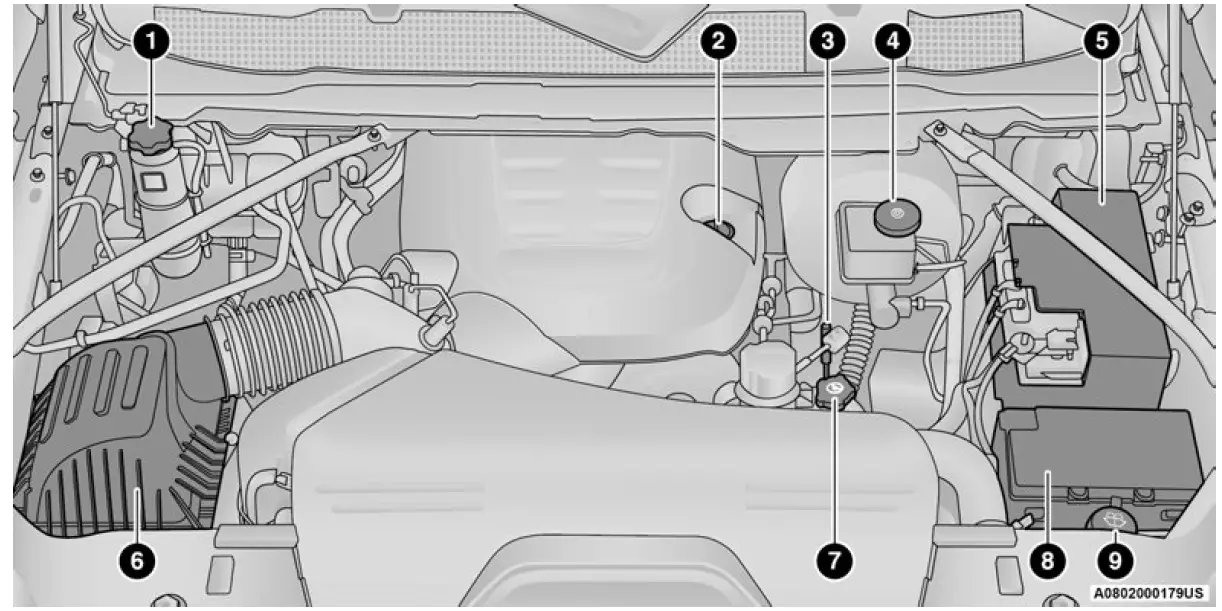
- Engine Coolant Pressure Cap
- Engine Oil Fill
- Engine Oil Dipstick
- Brake Fluid Reservoir Cap
- Battery
- Engine Air Cleaner Filter
- Power Steering Reservoir Cap
- Power Distribution Center (Fuses)
- Washer Fluid Reservoir Cap
6.7L DIESEL ENGINE — 6-SPEED 68RFE 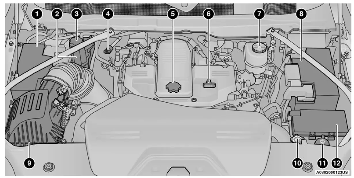
- Battery
- Engine Coolant Pressure Reservoir
- Engine Coolant Reservoir Cap
- Automatic Transmission Dipstick
- Engine Oil Fill
- Engine Oil Dipstick
- Brake Fluid Reservoir Cap
- Battery
- Engine Air Cleaner Filter
- Power Steering Reservoir Cap
- Washer Fluid Reservoir Cap
- Power Distribution Center (Fuses)
6.7L DIESEL ENGINE — 6-SPEED AS69RC HD
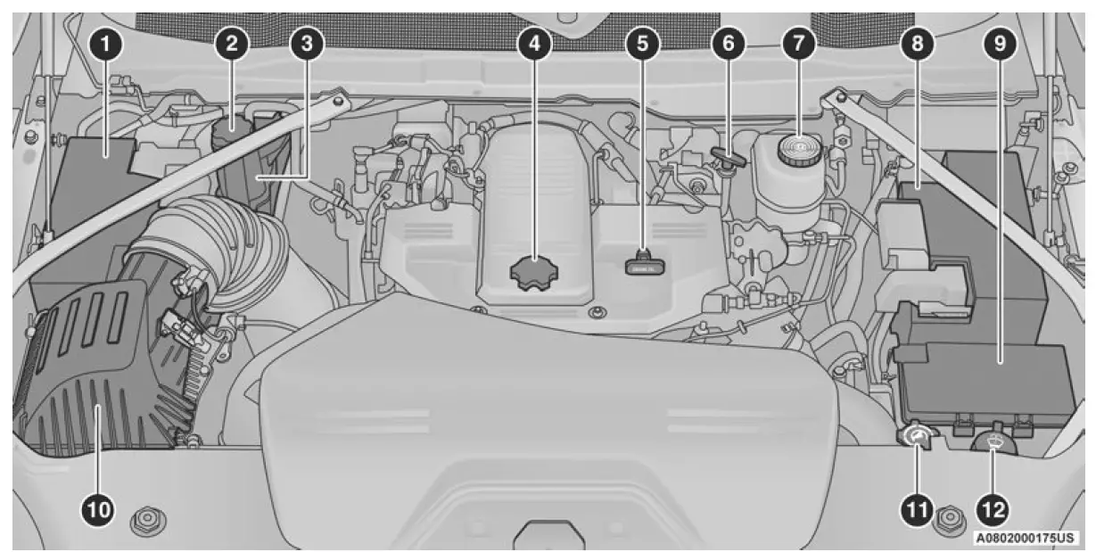
- Battery
- Engine Coolant Pressure Cap
- Engine Coolant Pressure Reservoir
- Engine Oil Fill
- Engine Oil Dipstick
- Automatic Transmission Dipstick
- Brake Fluid Reservoir Cap
- Battery
- Power Distribution Center (Fuses)
- Engine Air Cleaner Filter
- Power Steering Reservoir Cap
- Washer Fluid Reservoir Cap
CHECKING OIL LEVEL
To ensure proper engine lubrication, the engine oil must be maintained at the correct level. Check the oil level at regular intervals, such as every fuel stop. The best time to check the engine oil level is about five minutes after a fully warmed up engine is shut off.
Checking the oil while the vehicle is on level ground will improve the accuracy of the oil level readings.
There are four possible dipstick types:
- Crosshatched zone.
Crosshatched zone marked SAFE. - Crosshatched zone marked with MIN at the low end of the range and MAX at the high end of the range.
Crosshatched zone marked with dimples at the MIN and the MAX ends of the range.
NOTE:
Always maintain the oil level within the crosshatch markings on the dipstick.
Adding 1 qt (1 L) of oil when the reading is at the low end of the dipstick range will raise the oil level to the high end of the range marking.
CAUTION!
Overfilling or underfilling the crankcase will cause oil aeration or loss of oil pressure. This could damage your engine.
ADDING WASHER FLUID
The fluid reservoir is located under the hood and the fluid level should be checked at regular intervals. Fill the reservoir with windshield washer solvent only (not radiator antifreeze). When refilling the washer fluid reservoir, take some washer fluid and apply it to a cloth or towel and wipe the wiper blades clean. This will help blade performance.
To prevent freeze-up of your windshield washer system in cold weather, select a solution or mixture that meets or exceeds the temperature range of your climate. This rating information can be found on most washer fluid containers.
WARNING!
Commercially available windshield washer solvents are flammable. They could ignite and burn you. Care must be exercised when filling or working around the washer solution.
After the engine has warmed up, operate the defroster for a few minutes to reduce the possibility of smearing or freezing the fluid on the cold windshield. Windshield washer solution used with water as directed on the container, aids cleaning action, reduces the freezing point to avoid line clogging, and is not harmful to paint or trim.
MAINTENANCE-FREE BATTERY
Your vehicle is equipped with a maintenance-free battery. You will never have to add water, and periodic maintenance is not required.
WARNING!
- Battery fluid is a corrosive acid solution and can burn or even blind you. Do not allow battery fluid to contact your eyes, skin, or clothing. Do not lean over a battery when attaching clamps. If acid splashes in eyes or on skin, flush the area immediately with large amounts of water page 361.
- Battery gas is flammable and explosive. Keep flame or sparks away from the battery. Do not use a booster battery or any other booster source with an output greater than 12 Volts. Do not allow cable clamps to touch each other.
- Battery posts, terminals, and related accessories contain lead and lead compounds. Wash hands after handling.
CAUTION!
- It is essential when replacing the cables on the battery that the positive cable is attached to the positive post and the negative cable is attached to the negative post. Battery posts are marked positive (+) and negative (-) and are identified on the battery case. Cable clamps should be tight on the terminal posts and free of corrosion.
- If a “fast charger” is used while the battery is in the vehicle, disconnect both vehicle battery cables before connecting the charger to the battery. Do not use a “fast charger” to provide starting voltage.
PRESSURE WASHING
Cleaning the engine compartment with a high pressure washer is not recommended.
CAUTION!
Precautions have been taken to safeguard all parts and connections however, the pressure generated by these machines is such that complete protection against water ingress cannot be guaranteed.
VEHICLE MAINTENANCE
An authorized dealer has the qualified service personnel, special tools, and equipment to perform all service operations in an expert manner.
Service Manuals are available which include detailed service information for your vehicle. Refer to these Service Manuals before attempting any procedure yourself.
NOTE:
Intentional tampering with emissions control systems may void your warranty and could result in civil penalties being assessed against you.
WARNING!
You can be badly injured working on or around a motor vehicle. Only do service work for which you have the knowledge and the proper equipment. If you have any doubt about your ability to perform a service job, take your vehicle to a competent mechanic.
ENGINE OIL
Engine Oil Selection — Gasoline Engine
Use only the manufacturer’s recommended fluid page 446.
NOTE:
Hemi engines (6.4L) at times can tick right after startup and then quiet down after approximately 30 seconds. This is normal and will not harm the engine. This characteristic can be caused by short drive cycles. For example, if the vehicle is started then shut off after driving a short distance. Upon restarting, you may experience a ticking sound. Other causes could be if the vehicle is unused for an extended period of time, incorrect oil, extended oil changes or extended idling. If the engine continues to tick or if the Malfunction Indicator Light (MIL) comes on, see the nearest authorized dealer.
Engine Oil Selection — Diesel Engine
Use only the manufacturer’s recommended fluid page 446.
American Petroleum Institute (API)
Approved Engine Oil
These symbols mean that the oil has been certified by the API. The manufacturer only recommends API trademark oils.
 The API Starburst trademark certifies 0W-20, 0W-30 and 5W-30 engine oils.
 The API Donut trademark certifies 0W-40 and 5W-40 engine oil.
For diesel engines, oils with a high ash content may produce damaging deposits on cylinder head valves and/or after treatment system damage.
A maximum sulfated ash content of 1.00 mass % is recommended for all oil used in the engine.
The same oil change interval is to be followed for synthetic oil as for petroleum-based oil. Also, synthetic oil must meet the same performance specifications as petroleum oil.
CAUTION!
Do not use chemical flushes in your engine oil as the chemicals can damage your engine. Such damage is not covered by the New Vehicle Limited Warranty.
Synthetic Engine Oils
Your engine was designed for synthetic engine oils, only use synthetic API approved engine oils.
Synthetic engine oils which do not have both the correct API trademark and the correct SAE viscosity grade numbers should not be used.
Materials Added To Engine Oil
The manufacturer strongly recommends against the addition of any additives (other than leak detection dyes) to the engine oil. Engine oil is an engineered product and its performance may be impaired by supplemental additives.
Disposing Of Used Engine Oil And Oil Filters
Care should be taken in disposing of used engine oil and oil filters from your vehicle. Used oil and oil filters, indiscriminately discarded, can present a problem to the environment. Contact an authorized dealer, service station or governmental agency for advice on how and where used oil and oil filters can be safely discarded in your area.
ENGINE OIL FILTER
The engine oil filter should be replaced with a new filter at every engine oil change.
Engine Oil Filter Selection
A full-flow type disposable oil filter should be used for replacement. The quality of replacement filters varies considerably. Only high quality Mopar® certified filters should be used. If a Mopar® Engine Oil Filter is unavailable, only use filters that meet or exceed SAE/USCAR-36 Filter Performance Requirements.
ENGINE AIR CLEANER FILTER
For the proper maintenance intervals page 369.
WARNING!
The air induction system (air cleaner, hoses, etc.) can provide a measure of protection in the case of engine backfire. Do not remove the air induction system (air cleaner, hoses, etc.) unless such removal is necessary for repair or maintenance. Make sure that no one is near the engine compartment before starting the vehicle with the air induction system (air cleaner, hoses, etc.) removed. Failure to do so can result in serious personal injury.
Engine Air Cleaner Filter Selection
The quality of replacement engine air cleaner filters varies considerably. Only high quality filters should be used to ensure most efficient service. Mopar® engine air cleaners are a high quality filter and are recommended.
Engine Air Cleaner Filter Inspection And Replacement — Gasoline Engine
NOTE:
When replacing the engine air cleaner filter on vehicles equipped with a 6.4L gasoline engine, replace with a dry (non-oiled) filter only.
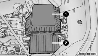
Engine Air Cleaner Filter Removal
- With suitable tool fully loosen (six) fasteners on engine air cleaner filter cover.
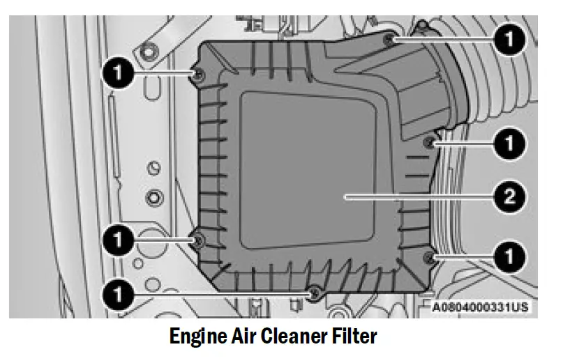
- Fasteners
- Engine Air Cleaner Filter Cover
- Lift the engine air cleaner filter cover to access the engine air cleaner filter.
- Remove the engine air cleaner filter from the housing assembly.
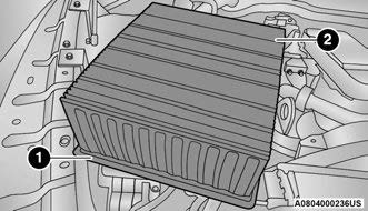
 Engine Air Cleaner Filter Assembly
 - Engine Air Cleaner Filter Cover
- Engine Air Cleaner Filter
Engine Air Cleaner Filter Installation
NOTE:
Inspect and clean the housing if significant dirt or debris is present before replacing the engine air cleaner filter.
- Install the engine air cleaner filter into the housing assembly with the engine air cleaner filter inspection surface facing downward.
- Install the engine air cleaner filter cover onto the housing assembly.
- Tighten the fasteners (six) on the engine air cleaner filter assembly.
CAUTION!
Do not overtighten the engine air cleaner filter cover lid screws or damage may result.
Engine Air Cleaner Filter Inspection and Replacement — Diesel Engine
Engine Air Cleaner Filter Removal
Using a suitable tool, fully loosen (six) fasteners on engine air cleaner filter cover.
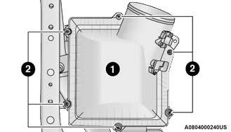 Engine Air Cleaner Filter Cover
- Screws
- Lift the engine air cleaner filter cover to access the engine air cleaner filter.
- Remove the engine air cleaner filter from the housing assembly.
 Engine Air Cleaner Filter
- Engine Air Cleaner Filter Inspection Surface
Engine Air Cleaner Filter Installation
NOTE:
Inspect and clean the housing if significant dirt or debris is present before replacing the engine air cleaner filter.
- Install the engine air cleaner into the housing assembly with the engine air cleaner filter inspection surface facing downward.
- Install the engine air cleaner filter cover onto the housing assembly locating tabs.
- Tighten (6) screws to secure the engine air cleaner filter cover to the housing assembly.
CAUTION!
Always observe the position of the trailer and surroundings using the camera and mirrors to avoid damage to the truck or trailer.
AIR CONDITIONER MAINTENANCE
For best possible performance, your air conditioner should be checked and serviced by an authorized dealer at the start of each warm season. This service should include cleaning of the condenser fins and a performance test. Drive belt tension should also be checked at this time.
WARNING!
- Use only refrigerants and compressor lubricants approved by the manufacturer for your air conditioning system. Some unapproved refrigerants are flammable and can explode, injuring you. Other unapproved refrigerants or lubricants can cause the system to fail, requiring costly repairs. Refer to Warranty Information Book, for further warranty information.
The air conditioning system contains refrigerant under high pressure. To avoid risk of personal injury or damage to the system, adding refrigerant or any repair requiring lines to be disconnected should be done by an experienced technician.
CAUTION!
Do not use chemical flushes in your air conditioning system as the chemicals can damage your air conditioning components. Such damage is not covered by the New Vehicle Limited Warranty.
Refrigerant Recovery And Recycling — R-134a — (If Equipped)
R-134a Air Conditioning Refrigerant is a Hydrofluo-rocarbon (HFC) that is an ozone-friendly substance. The manufacturer recommends that air conditioning service be performed by an authorized dealer or other service facilities using recovery and recycling equipment.
NOTE:
Use only manufacturer approved A/C system PAG compressor oil and refrigerants.
Refrigerant Recovery And Recycling — R-1234yf — (If Equipped)
R–1234yf Air Conditioning Refrigerant is a Hydrofluo-roolefin (HFO) that is endorsed by the Environmental Protection Agency and is an ozone-friendly substance with a low global-warming potential. The manufacturer recommends that air conditioning service be performed by an authorized dealer using recovery and recycling equipment.
NOTE:
Use only manufacturer approved A/C system PAG compressor oil, and refrigerants.
Cabin Air Filter Replacement
For the proper maintenance intervals page 369.
WARNING!
Do not remove the cabin air filter while the vehicle is running, or while the ignition is in the ACC or ON/RUN mode. With the cabin air filter removed and the blower operating, the blower can contact hands and may propel dirt and debris into your eyes, resulting in personal injury.
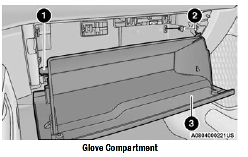
The cabin air filter is located in the fresh air inlet behind the glove compartment. Perform the following procedure to replace the filter:
- Open the glove compartment and remove all contents.
- With the glove compartment door open, remove the glove compartment tension tether and tether clip by sliding the clip toward the face of the glove compartment door. Lift the clip out of glove compartment door and release into dash panel.
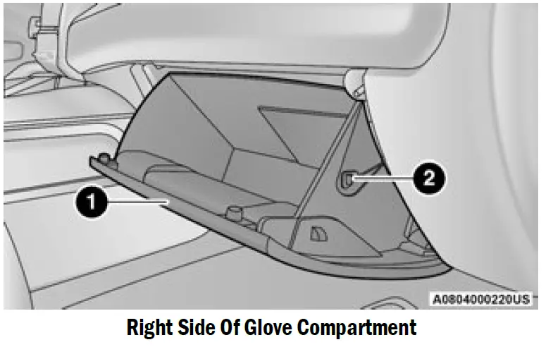
- Glove Compartment Door
- Glove Compartment Tension Tether
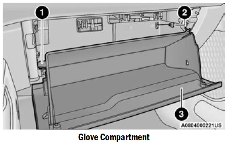
- There are travel stops on both sides of the glove compartment. Push inward on right side of the glove compartment travel stop to disengage the stop. Then pull the right of the glove compartment outward (away from the hinge) to disengage the right side of the compartment from the hinge. Continue by removing the left side from the hinge by slightly lowering the compartment while pulling outward until it is completely disengaged from the hinge.
 Glove Compartment Travel Stop
 - Glove Compartment Tension Tether 3
- Glove Compartment Door
Remove the filter cover by pushing in on the finger tabs on each end of the filter cover.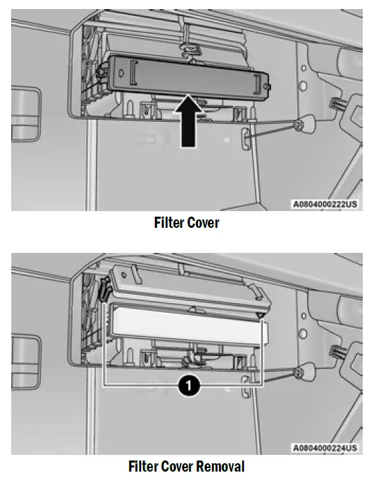
- Remove the cabin air filter by pulling it straight out of the housing.
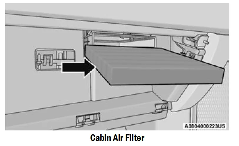
- Install the cabin air filter with the arrow on the filter pointing toward the floor. When installing the filter cover, press on each end until you hear an audible click.
CAUTION!
The cabin air filter is identified with an arrow to indicate airflow direction through the filter. Failure to properly install the filter will result in the need to replace it more often. - Reinstall the glove compartment on the hinges.
- Pull the tension tether outward and reinstall the glove compartment past the travel stops by pushing in on the glove compartment sides.
- Glove Compartment Travel Stop
- Glove Compartment Tension Tether
- Glove Compartment Door
NOTE:
Ensure the glove compartment door hinges and glove compartment travel stops are fully engaged.
- Reattach the glove compartment tension tether by inserting the tether clip in the glove compartment and sliding the clip away from the face of the glove compartment door.
ACCESSORY DRIVE BELT INSPECTION
WARNING!
- Do not attempt to inspect an accessory drive belt with vehicle running.
- When working near the radiator cooling fan, disconnect the fan motor lead. The fan is temperature controlled and can start at any time regardless of ignition mode. You could be injured by the moving fan blades.
- You can be badly injured working on or around a motor vehicle. Only do service work for which you have the knowledge and the proper equipment.
If you have any doubt about your ability to perform a service job, take your vehicle to a competent mechanic.
When inspecting accessory drive belts, small cracks that run across ribbed surface of belt from rib to rib, are considered normal. These are not a reason to replace belt. However, cracks running along a rib (not across) are not normal. Any belt with cracks running along a rib must be replaced. Also have the belt replaced if it has excessive wear, frayed cords or severe glazing.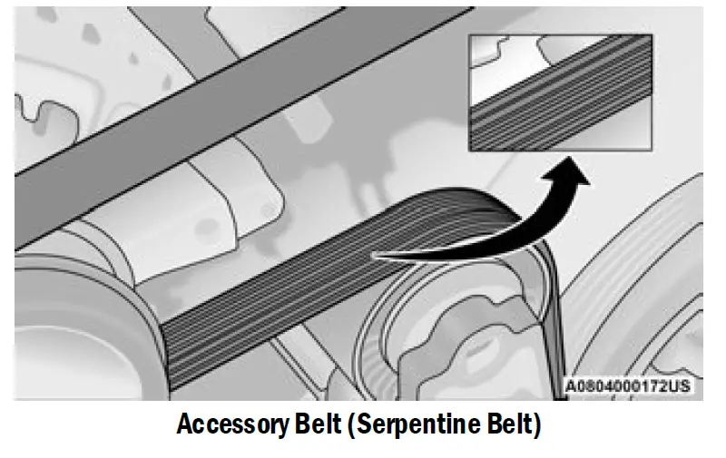 Conditions that would require replacement:
- Rib chunking (one or more ribs has separated from belt body)
- Rib or belt wear
- Longitudinal belt cracking (cracks between two ribs)
- Belt slips
- Groove jumping (belt does not maintain correct position on pulley)
- Belt broken (identify and correct problem before new belt is installed)
- Noise (objectionable squeal, squeak, or rumble is heard or felt while drive belt is in operation)
Some conditions can be caused by a faulty component such as a belt pulley. Belt pulleys should be carefully inspected for damage and proper alignment.
Belt replacement on some models requires the use of special tools, we recommend having your vehicle serviced at an authorized dealer.
DRAINING FUEL/WATER SEPARATOR FILTER — DIESEL ENGINE
There are two fuel filter assemblies. One is located on the driver’s side of the engine. The best access to this water drain valve is from under the hood. The second one is on the under body, located in front of the rear axle above the drive shaft. The best access to this water drain valve is from under the vehicle.
CAUTION!
- Do not drain the fuel/water separator filter when the engine is running.
Diesel fuel will damage blacktop paving surfaces. Drain the filter into an appropriate container.
If water is detected in the water separator while the engine is running, or while the ignition switch is in the ON position, the Water In Fuel Indicator Light will illuminate and an audible chime will be heard five times. At this point you should stop the engine and drain the water from both of the filters.
CAUTION!
If the Water In Fuel Indicator Light remains on, DO NOT START the engine before you drain water from the fuel filters to avoid engine damage.
If the Water In Fuel Indicator Light comes on and a single chime is heard while you are driving, or with the ignition switch in the ON position, there may be a problem with your water separator wiring or sensor. See an authorized dealer for service.
Upon proper draining of the water from both fuel filters, the Water In Fuel Indicator Light will remain illuminated for approximately 10 seconds. If the water was drained while the engine was running, the Water In Fuel Indicator Light may remain on for approximately three minutes.
NOTE:
Care should be taken in disposing of used fluids from your vehicle. Used fluids, indiscriminately discarded, can present a problem to the environment. Contact an authorized dealer, service station, or government agency for advice on recycling programs and for where used fluids and filters can be properly disposed of in your area.
Drain the fuel/water separator filters when the Water In Fuel Indicator Light is ON. Within 10 minutes of vehicle shutdown, turn the engine mounted filter drain valve
(located on the side of the filter assembly) counterclockwise 1/4 turn, and turn the under body mounted filter drain valve (located on the bottom of the filter assembly) counterclockwise 1 full turn. Then turn the ignition switch to the ON position, and allow any accumulated water to drain. Leave the drain valve open until all water and contaminants have been removed. When clean fuel is visible, close the drain valve following these guidelines:
- Rotate the drain clockwise to close until you feel resistance from the internal seal.
- Continue turning the drain 1/2 of a turn to properly compress the seal.
NOTE:
Over-compression of the seal due to over-tightening of the drain will damage the seal, cause a leak, and require the entire sensor to be replaced. - Turn the ignition switch to OFF.
The sensor drain should not be over-tightened during normal service operations to avoid internal damage and future fuel leaks. The drain should be closed and secured without the use of tools.
If more than a couple ounces/milliliters of fuel have been drained, follow the directions page 390.
ENGINE MOUNTED FUEL FILTER REPLACEMENT — DIESEL ENGINE
NOTE:
Using a fuel filter that does not meet the manufacturer’s filtration and water separating requirements can severely impact fuel system life and reliability.
The engine mounted filter housing is equipped with a No-Filter-No-Run (NFNR) feature. Engine will not run if:
-
- No filter is installed.
- Inferior/Non-approved filter is used. Use of OEM filter is required to ensure vehicle will run.
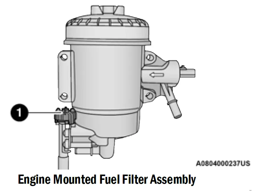 Drain Valve
CAUTION!
- Diesel fuel will damage blacktop paving surfaces. Drain the filter into an appropriate container.
Do not prefill the fuel filter when installing a new fuel filter. There is a possibility debris could be introduced into the fuel filter during this action. It is best to install the filter dry and allow the in-tank lift pump to prime the fuel system..
- Ensure engine is turned off.
- Place drain pan under the fuel filter drain hose.
- Open the water drain valve a quarter turn counter-clockwise and completely drain fuel and water into the approved container.
- Close the water drain valve.
- Remove lid using a socket or strap wrench. Rotate counterclockwise for removal. Remove used o-ring and discard it.
- Remove the used filter cartridge from the housing and dispose of according to your local regulations.
- Wipe clean the sealing surfaces of the lid and housing.
- Install new o-ring back into ring groove on the filter housing and lubricate with clean engine oil.
- Remove new filter cartridge from plastic bag and install into housing.
NOTE:
Do not remove cartridge from bag until you reach this step in order to keep cartridge clean. - Push down on the cartridge to ensure it is properly seated. Do not pre-fill the filter housing with fuel.
- Install lid onto housing and tighten to 22.5 ft-lb (30.5 Nm). Do not overtighten the lid.
- Prime the engine, then start the engine and confirm there are no leaks page 390.
UNDERBODY MOUNTED FUEL FILTER REPLACEMENT — DIESEL ENGINE
NOTE:
- Using a fuel filter that does not meet the manufacturer’s filtration and water separating requirements can severely impact fuel system life and reliability.
- The underbody mounted filter housing will cause the engine not to run if no filter is installed.
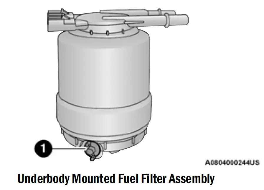 Drain Valve
CAUTION!
- Diesel fuel will damage blacktop paving surfaces. Drain the filter into an appropriate container.
Do not prefill the fuel filter when installing a new fuel filter. There is a possibility debris could be introduced into the fuel filter during this action. It is best to install the filter dry and allow the in-tank lift pump to prime the fuel system.
- Ensure engine is turned off.
- Place drain pan under the fuel filter drain hose.
- Open the water drain valve one full turn counter-clockwise and completely drain fuel and water into the approved container.
Close the water drain valve. - Remove lid using a socket or strap wrench. Rotate counterclockwise for removal. Remove used o-ring and discard it.
- Remove the used filter cartridge from the housing and dispose of according to your local regulations.
- Wipe clean the sealing surfaces of the lid and housing.
- Install new o-ring back into ring groove on the filter housing and lubricate with clean engine oil.
NOTE:
Water In Fuel (WIF) sensor is reusable. Service kit comes with new o-ring for filter canister and WIF sensor.
PRIMING IF THE ENGINE HAS RUN OUT OF FUEL — DIESEL ENGINE
WARNING!
Do not open the high pressure fuel system with the engine running. Engine operation causes high fuel pressure. High pressure fuel spray can cause serious injury or death.
- Add a substantial amount of fuel to the tank, approx-imately 2 to 5 gal (8 L to 19 L).
- Three priming cycles must be completed. Turn ignition to the RUN position and wait approximately 30 seconds. This will activate the in tank fuel pump. Turn the ignition switch to the off position, and leave off for at least 30 seconds. Repeat this procedure three times before cranking the engine.
- Start the engine using the “Normal Starting” procedure page 128.
- Once the engine starts, allow the engine to idle for a minimum of 30 seconds.
CAUTION!
Do not engage the starter motor for more than 15 seconds at a time. Allow two minutes between the cranking intervals.
NOTE:
The engine may run rough until the air is forced from all the fuel lines.
WARNING!
Do not use alcohol or gasoline as a fuel blending agent. They can be unstable under certain conditions and be hazardous or explosive when mixed with diesel fuel.
CAUTION!
Due to lack of lubricants in alcohol or gasoline, the use of these fuels can cause damage to the fuel system.
NOTE:
- A maximum blend of 5% biodiesel, meeting ASTM specification D-975 may be used with your Cummins® diesel engine.
A maximum blend of 20% biodiesel, meeting ASTM specification D-7467 may be used with your Cummins® diesel engine.
Use of biodiesel mixture in excess of 20% can negatively impact the fuel filter’s ability to separate water from the fuel, resulting in high pressure fuel system corrosion or damage. - Ethanol blends are not recommended or approved for use with your Cummins® diesel engine.
- In addition, commercially available fuel additives are not necessary for the proper operation of your Cummins® diesel engine.
INTERVENTION REGENERATION STRATEGY — MESSAGE PROCESS FLOW
The Cummins® diesel engine meets all Environmental Protection Agency (EPA) Heavy Duty Diesel Engine Emissions Standards, resulting in one of the lowest emitting diesel engines ever produced.
To achieve these emissions standards, your vehicle is equipped with a state-of-the-art engine and exhaust system. The engine and exhaust after-treatment system work together to achieve the EPA Heavy Duty Diesel Engine Emissions Standards. These systems are seamlessly integrated into your vehicle and managed by the Cummins® Powertrain Control Module (PCM). The PCM manages engine combustion to allow the exhaust system’s catalyst to trap and burn Particulate Matter (PM) pollutants, with no input or interaction on your part.
If the engine is allowed to idle or the truck is driven on low engine speed drive cycles for more than two hours, the system will automatically enter an emissions operating mode that will increase the engine idle speed to 900 RPM. While in this mode, which is designed to help maintain the Diesel Particulate Filter, the engine idle speed will return to normal when the brake pedal is applied. A small change in engine tone or a slight change in engine performance while accelerating may also be noticeable at speeds below 20 mph (32 km/h). This operating mode may last for up to an hour of idle time, or around 20 minutes of driving time.
Additionally, your vehicle has the ability to alert you to additional maintenance required on your truck or engine page 104.
WARNING!
A hot exhaust system can start a fire if you park over materials that can burn. Such materials might be grass or leaves coming into contact with your exhaust system. Do not park or operate your vehicle in areas where your exhaust system can contact anything that can burn.
DIESEL EXHAUST FLUID (DEF)
DEF sometimes known simply by the name of its active component, UREA—is a key component of Selective Catalytic Reduction (SCR) systems, which help diesel vehicles meet stringent emission regulations. DEF is a liquid reducing agent that reacts with engine exhaust in the presence of a catalyst to convert smog-forming Nitrogen Oxides (NOx) into harmless nitrogen and water vapor page 446.
You can receive assistance in locating DEF by contacting an authorized dealer.
BODY LUBRICATION
Locks and all body pivot points, including such items as seat tracks, door hinge pivot points and rollers, liftgate, tailgate, decklid, sliding doors and hood hinges, should be lubricated periodically with a lithium-based grease, such as Mopar® Spray White Lube to ensure quiet, easy operation and to protect against rust and wear. Prior to the application of any lubricant, the parts concerned should be wiped clean to remove dust and grit; after lubricating, excess oil and grease should be removed. Particular attention should also be given to hood latching components to ensure proper function. When performing other underhood services, the hood latch, release mechanism and safety catch should be cleaned and lubricated.
The external lock cylinders should be lubricated twice a year, preferably in the Autumn and Spring. Apply a small amount of a high quality lubricant, such as Mopar® Lock Cylinder Lubricant directly into the lock cylinder.
WINDSHIELD WIPER BLADES
Clean the rubber edges of the wiper blades and the windshield periodically with a sponge or soft cloth and a mild nonabrasive cleaner. This will remove accumulations of salt or road film.
Operation of the wipers on dry glass for long periods may cause deterioration of the wiper blades. Always use washer fluid when using the wipers to remove salt or dirt from a dry windshield.
Avoid using the wiper blades to remove frost or ice from the windshield. Keep the blade rubber out of contact with petroleum products such as engine oil, gasoline, etc.
NOTE:
Life expectancy of wiper blades varies depending on geographical area and frequency of use. Poor perfor-mance of blades may be present with chattering, marks, water lines or wet spots. If any of these conditions are present, clean the wiper blades or replace as necessary.
The wiper blades and wiper arms should be inspected periodically, not just when wiper performance problems are experienced. This inspection should include the following points:
- Wear or uneven edges
Foreign material
Hardening or cracking
Deformation or fatigue
If a wiper blade or wiper arm is damaged, replace the affected wiper arm or blade with a new unit. Do not attempt to repair a wiper arm or blade that is damaged.
Wiper Blade Removal/Installation
CAUTION!
Do not allow the wiper arm to spring back against the glass without the wiper blade in place or the glass may be damaged.
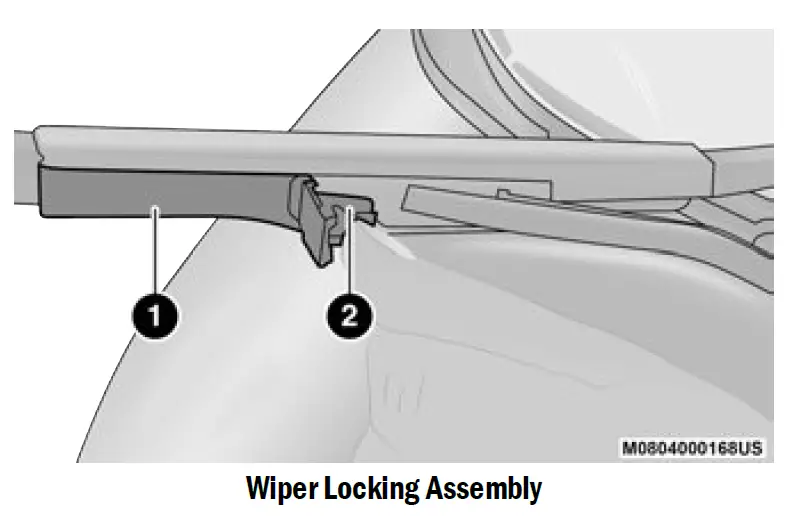
- Lift the wiper arm to raise the wiper blade off of the glass, until the wiper arm is in the full up position.
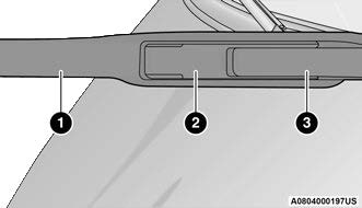 Windshield Wiper Arm And Blade
- Wiper
- Locking Tab
- Wiper Arm
- To disengage the wiper blade from the wiper arm, flip up the locking tab.
- Wiper
- Locking Tab
- Tilt the lower end of the wiper blade away from the arm and with one finger, push the release tab toward the wiper arm.Locking Tab
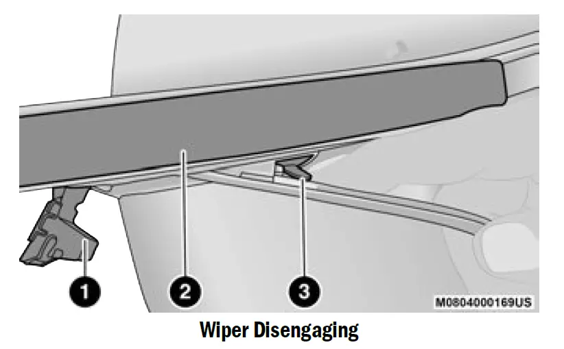
- Wiper
- Release Tab
- Slide the wiper blade down towards the base of the wiper arm.
-
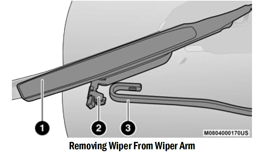 Wiper
Wiper- Locking Tab
- Wiper Arm J Hook
- Gently lower the wiper arm onto the glass.
Installing The Front Wipers
- Lift the wiper arm off of the glass, until the wiper arm is in the full up position.
- Position the wiper blade under the hook on the tip of the wiper arm with the wiper locking tab open.
- Insert the receiver bracket on the wiper assembly into the hook on the tip of the arm through the opening in the wiper blade under the locking tab.
- Slide the wiper blade up into the hook on the wiper arm until it is latched (engagement will be accompanied by an audible click). Fold down the latch release tab and snap it into its locked position.
- Gently lower the wiper blade onto the glass.
EXHAUST SYSTEM
The best protection against carbon monoxide entry into the vehicle body is a properly maintained engine exhaust system.
If you notice a change in the sound of the exhaust system; or if exhaust fumes can be detected inside the vehicle; or when the underside or rear of the vehicle is damaged; have an authorized technician inspect the complete exhaust system and adjacent body areas for broken, damaged, deteriorated, or mispositioned parts. Open seams or loose connections could permit exhaust fumes to seep into the passenger compartment. In addition, have the exhaust system inspected each time the vehicle is raised for lubrication or oil changes. Replace as required.
WARNING!
- Exhaust gases can injure or kill. They contain Carbon Monoxide (CO), which is colorless and odorless. Breathing it can make you unconscious and can eventually poison you page 348.
- A hot exhaust system can start a fire if you park over materials that can burn. Such materials might be grass or leaves coming into contact with your exhaust system. Do not park or operate your vehicle in areas where your exhaust system can contact anything that can burn.
CAUTION!
- The catalytic converter requires the use of unleaded fuel only. Leaded gasoline will destroy the effective-ness of the catalyst as an emissions control device and may seriously reduce engine performance and cause serious damage to the engine.
- Damage to the catalytic converter can result if your vehicle is not kept in proper operating condition. In the event of engine malfunction, particularly involving engine misfire or other apparent loss of performance, have your vehicle serviced promptly. Continued operation of your vehicle with a severe malfunction could cause the converter to overheat, resulting in possible damage to the converter and vehicle.
Under normal operating conditions, the catalytic converter will not require maintenance. However, it is important to keep the engine properly tuned to ensure proper catalyst operation and prevent possible catalyst damage.
NOTE:
Intentional tampering with emissions control systems can result in civil penalties being assessed against you.
In unusual situations involving grossly malfunctioning engine operation, a scorching odor may suggest severe and abnormal catalyst overheating. If this occurs, stop the vehicle, turn off the engine and allow it to cool. Service, including a tune-up to manufacturer’s specifications, should be obtained immediately.
To minimize the possibility of catalytic converter damage:
- Do not interrupt the ignition when the transmission is in gear and the vehicle is in motion.
Do not try to start the vehicle by pushing or towing the vehicle. - Do not idle the engine with any ignition components disconnected or removed, such as during diagnostic testing, or for prolonged periods during very rough idle or malfunctioning operating conditions.
COOLING SYSTEM
WARNING!
- You or others can be badly burned by hot engine coolant (antifreeze) or steam from your radiator. If you see or hear steam coming from under the hood, do not open the hood until the radiator has had time to cool. Never open a cooling system pressure cap when the radiator or coolant bottle is hot.
- Keep hands, tools, clothing, and jewelry away from the radiator cooling fan when the hood is raised. The fan starts automatically and may start at any time, whether the engine is running or not.
- When working near the radiator cooling fan, disconnect the fan motor lead or turn the ignition to the OFF mode. The fan is temperature controlled and can start at any time the ignition is in the ON mode.
Engine Coolant Checks
Check the engine coolant (antifreeze) protection every 12 months (before the onset of freezing weather, where applicable). If the engine coolant is dirty or rusty in appearance, the system should be drained, flushed and refilled with fresh coolant. Check the front of the A/C condenser or radiator for any accumulation of bugs, leaves, etc. If dirty, clean by gently spraying water from a garden hose vertically down the face of the A/C condenser or the back of the radiator core.
Check the engine cooling system hoses for brittle rubber, cracking, tears, cuts and tightness of the connection at the coolant recovery bottle and radiator. Inspect the entire system for leaks.
DO NOT REMOVE THE COOLANT PRESSURE CAP WHEN THE COOLING SYSTEM IS HOT.
Cooling System — Drain, Flush And Refill
NOTE:
Some vehicles require special tools to add coolant properly. Failure to fill these systems properly could lead to severe internal engine damage. If any coolant is needed to be added to the system please contact an authorized dealer.
If the engine coolant (antifreeze) is dirty or contains visible sediment, have an authorized dealer clean and flush with Organic Additive Technology (OAT) coolant (conforming to MS.90032).
For the proper maintenance intervals page 369.
Selection Of Coolant
For further information page 446.
NOTE:
- Mixing of engine coolant (antifreeze) other than specified Organic Additive Technology (OAT) engine coolant, may result in engine damage and may decrease corrosion protection. OAT engine coolant is different and should not be mixed with Hybrid Organic Additive Technology (HOAT) engine coolant or any “globally compatible” coolant. If a non-OAT engine coolant is introduced into the cooling system in an emergency, the cooling system will need to be drained, flushed, and refilled with fresh OAT coolant (conforming to MS.90032), by an authorized dealer as soon as possible.
- Do not use water alone or alcohol-based engine coolant products. Do not use additional rust inhibitors or antirust products, as they may not be compatible with the radiator engine coolant and may plug the radiator.
- This vehicle has not been designed for use with propylene glycol-based engine coolant. Use of propylene glycol-based engine coolant is not recommended.
- Some vehicles require special tools to add coolant properly. Failure to fill these systems properly could lead to severe internal engine damage. If any coolant is needed to be added to the system please contact an authorized dealer.
Adding Coolant
Your vehicle has been built with an improved engine coolant (OAT coolant conforming to MS.90032) that allows extended maintenance intervals. This engine coolant (antifreeze) can be used up to ten years or 150,000 miles (240,000 km) before replacement. To prevent reducing this extended maintenance period, it is important to use the same engine coolant (OAT coolant conforming to MS.90032) throughout the life of your vehicle.
Please review these recommendations for using Organic Additive Technology (OAT) engine coolant that meets the requirements of the manufacturer Material Standard MS.90032. When adding engine coolant:
- We recommend using Mopar® Antifreeze/Coolant 10 Year/150,000 Mile (240,000 km) Formula OAT that meets the requirements of the manufacturer Material Standard MS.90032.
- Mix a minimum solution of 50% OAT engine coolant that meets the requirements of the manufacturer Material Standard MS.90032 and distilled water. Use higher concentrations (not to exceed 70%) if temperatures below −34°F (−37°C) are anticipated. Please contact an authorized dealer for assistance.
- Use only high purity water such as distilled or deionized water when mixing the water/engine coolant (anti-freeze) solution. The use of lower quality water will reduce the amount of corrosion protection in the engine cooling system.
NOTE:
- It is the owner’s responsibility to maintain the proper level of protection against freezing according to the temperatures occurring in the area where the vehicle is operated.
- Some vehicles require special tools to add coolant properly. Failure to fill these systems properly could lead to severe internal engine damage. If any coolant is needed to be added to the system, please contact a local authorized dealer.
- Mixing engine coolant types is not recommended and can result in cooling system damage. If HOAT and OAT coolant are mixed in an emergency, have an authorized dealer drain, flush, and refill with OAT coolant (conforming to MS.90032) as soon as possible.
Cooling System Pressure Cap
The cap must be fully tightened to prevent loss of engine coolant (antifreeze), and to ensure that engine coolant will return to the radiator from the coolant expansion bottle/recovery tank (if equipped).
The cap should be inspected and cleaned if there is any accumulation of foreign material on the sealing surfaces.
WARNING!
- Do not open hot engine cooling system. Never add engine coolant (antifreeze) when the engine is overheated. Do not loosen or remove the cap to cool an overheated engine. Heat causes pressure to build up in the cooling system. To prevent scalding or injury, do not remove the pressure cap while the system is hot or under pressure.
- Do not use a pressure cap other than the one specified for your vehicle. Personal injury or engine damage may result.
Disposal Of Used Coolant
Used ethylene glycol-based coolant (antifreeze) is a regulated substance requiring proper disposal. Check with your local authorities to determine the disposal rules for your community. To prevent ingestion by animals or children, do not store ethylene glycol-based coolant in open containers or allow it to remain in puddles on the ground: clean up any ground spills immediately. If ingested, seek emergency assistance immediately.
Coolant Level
The coolant bottle provides a quick visual method for determining that the engine coolant (antifreeze) level is adequate. With the engine off and cold, the level of the engine coolant in the bottle should be between the ranges indicated on the bottle.
The radiator normally remains completely full, so there is no need to remove the radiator cap unless checking for engine coolant freeze point or replacing engine coolant. Advise your service attendant of this. As long as the engine operating temperature is satisfactory, the coolant bottle need only be checked once a month.
When additional engine coolant is needed to maintain the proper level, it should be added to the coolant bottle. Do not overfill.
Cooling System Notes
NOTE:
When the vehicle is stopped after a few miles/kilo-meters of operation, you may observe vapor coming from the front of the engine compartment. This is normally a result of moisture from rain, snow, or high humidity accumulating on the radiator and being vaporized when the thermostat opens, allowing hot engine coolant (antifreeze) to enter the radiator.
If an examination of your engine compartment shows no evidence of radiator or hose leaks, the vehicle may be safely driven. The vapor will soon dissipate.
- Do not overfill the coolant expansion bottle.
- Check the coolant freeze point in the radiator and in the coolant expansion bottle. If engine coolant needs to be added, the contents of the coolant expansion bottle must also be protected against freezing.
- If frequent engine coolant additions are required, the cooling system should be pressure tested for leaks.
- Maintain engine coolant concentration at a minimum of 50% OAT coolant (conforming to MS.90032) and distilled water for proper corrosion protection of your engine which contains aluminum components.
- Make sure that the coolant expansion bottle overflow hoses are not kinked or obstructed.
- Keep the front of the radiator clean. If your vehicle is equipped with air conditioning, keep the front of the condenser clean.
- Do not change the thermostat for Summer or Winter operation. If replacement is ever necessary, install ONLY the correct type thermostat. Other designs may result in unsatisfactory engine cooling performance, poor gas mileage, and increased emissions.
CHARGE AIR COOLER — INTER-COOLER
The charge air cooler is positioned below the radiator and the air conditioner condenser. Air enters the engine through the air cleaner and passes through the turbocharger, where it is pressurized. This pressurized air rapidly reaches high temperature. The air is then directed through a hose to the charge air cooler and through another hose to the intake manifold of the engine. The air entering the engine has been cooled by about 50° to 100°F (10° to 38°C). This cooling process enables more efficient burning of fuel resulting in fewer emissions.
To guarantee optimum performance of the system, keep the surfaces of the charge air cooler, condenser and radiator clean and free of debris. Periodically check the hoses leading to and from the charge air cooler for cracks or loose clamps resulting in loss of pressure and reduced engine performance.
BRAKE SYSTEM
In order to ensure brake system performance, all brake system components should be inspected periodically page 256.
WARNING!
Riding the brakes can lead to brake failure and possibly a collision. Driving with your foot resting or riding on the brake pedal can result in abnormally high brake temperatures, excessive lining wear, and possible brake damage. You would not have your full braking capacity in an emergency.
Fluid Level Check — Brake Master Cylinder
The fluid level of the master cylinder should be checked whenever the vehicle is serviced, or immediately if the Brake System Warning Light is on. If necessary, add fluid to bring level within the designated marks on the side of the reservoir of the brake master cylinder. Be sure to clean the top of the master cylinder area before removing cap. With disc brakes, fluid level can be expected to fall as the brake pads wear. Brake fluid level should be checked when pads are replaced. If the brake fluid is abnormally low, check the system for leaks. For further information page 310.
- Use only manufacturer’s recommended brake fluid page 316. Using the wrong type of brake fluid can severely damage your brake system and/or impair its performance. The proper type of brake fluid for your vehicle is also identified on the original factory installed hydraulic master cylinder reservoir.To avoid contamination from foreign matter or moisture, use only new brake fluid or fluid that has been in a tightly closed container. Keep the master cylinder reservoir cap secured at all times. Brake fluid in a open container absorbs moisture from the air resulting in a lower boiling point. This may cause it to boil unexpectedly during hard or prolonged braking, resulting in sudden brake failure. This could result in a collision.
- Overfilling the brake fluid reservoir can result in spilling brake fluid on hot engine parts, causing the brake fluid to catch fire. Brake fluid can also damage painted and vinyl surfaces, care should be taken to avoid its contact with these surfaces.
- Do not allow petroleum based fluid to contaminate the brake fluid. Brake seal components could be damaged, causing partial or complete brake failure. This could result in a collision.
AUTOMATIC TRANSMISSION
Special Additives
The manufacturer strongly recommends against using any special additives in the transmission. Automatic Transmission Fluid (ATF) is an engineered product and its performance may be impaired by supplemental additives. Therefore, do not add any fluid additives to the transmission. Avoid using transmission sealers as they may adversely affect seals.
CAUTION!
Do not use chemical flushes in your transmission as the chemicals can damage your transmission components. Such damage is not covered by the New Vehicle Limited Warranty.
Fluid Level Check
The fluid level is preset at the factory and does not require adjustment under normal operating conditions. Routine fluid level checks are not required; therefore the transmission has no dipstick. An authorized dealer can check your transmission fluid level using special service tools. If you notice fluid leakage or transmission malfunction, visit an authorized dealer immediately to have the transmission fluid level checked. Operating the vehicle with an improper fluid level can cause severe transmission damage.
CAUTION!
If a transmission fluid leak occurs, visit an authorized dealer immediately. Severe transmission damage may occur. An authorized dealer has the proper tools to adjust the fluid level accurately.
Fluid Level Check — 6-Speed Transmission
It is best to check the fluid level when the transmission is at normal operating temperature (158-176°F / 70-80°C). This normally occurs after at least 15 miles (25 km) of driving. At normal operating temperature the fluid cannot be held comfortably between the fingertips. You can read the transmission temperature in the instrument cluster screen page 104.
Use the following procedure to check the transmission fluid level properly:
- Monitor the transmission temperature using the instrument cluster display, and operate the vehicle as required to reach the normal operating temperature. If the transmission is not functioning properly, or the vehicle cannot be driven, see the following Note and Caution about checking the fluid level at colder temperatures.
- Park the vehicle on level ground.
- Run the engine at normal idle speed for at least 60 seconds, and leave the engine running for the rest of this procedure.
- Fully apply the parking brake, and press the brake pedal.
- Place the gear selector momentarily into each gear position (allowing time for the transmission to fully engage in each position), ending with the transmission in PARK.
- Remove the dipstick by unlocking the cap, wipe it clean and reinsert it until seated.
- Remove the dipstick again and note the fluid level on both sides. The fluid level reading is only valid if there is a solid coating of oil on both sides of the dipstick. Note that the holes in the dipstick will be full of fluid if the actual level is at or above the hole.The fluid level should be between the “HOT” (upper) reference holes on the dipstick at normal operating temperature. If the fluid level is low, add fluid through the dipstick tube to bring it to the proper level. Do not overfill. Use ONLY the specified fluid page 448. After adding any quantity of oil through the dipstick tube, wait a minimum of two minutes for the oil to fully drain into the transmission before rechecking the fluid level.NOTE:
Oil level check can only be performed with the 44 inch dipstick blade with oil level indicator holes. If the vehicle is equipped with the 15 inch dipstick then a service dipstick will be required to check the oil.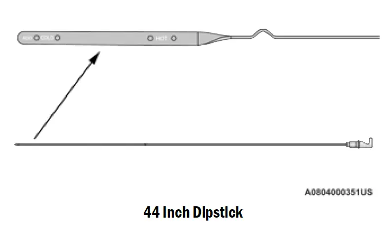 NOTE:
NOTE:
If it is necessary to check the transmission below the operating temperature, the fluid level should be between the two “COLD” (lower) holes on the dipstick with the fluid at 60-70°F / 16-21°C. Only use the COLD region of the dipstick as a rough reference when setting the fluid level after a transmission service or fluid change. Recheck the fluid level, and adjust as required, once the transmission reaches normal operating temperature.CAUTION!
If the fluid temperature is below 50°F (10°C) it may not register on the dipstick. Do not add fluid until the temperature is elevated enough to produce an accurate reading. Run the engine at idle, in PARK, to warm the fluid. - Reinsert the dipstick until fully seated and lock it down. The bending of the blade will orient the cap in the correct position. Do not force or rotate the cap into another position. Check for leaks. Release the parking brake.
Fluid And Filter Changes — 8-Speed
Transmission
Under normal operating conditions, the fluid installed at the factory will provide satisfactory lubrication for the life of the vehicle.
Routine fluid and filter changes are not required. However, change the fluid and filter if the fluid becomes contaminated (with water, etc.), or if the transmission is disassembled for any reason.
Fluid And Filter Changes — 6-Speed
Transmission
For the proper maintenance intervals page 369.
In addition, change the fluid and filters if the fluid becomes contaminated (with water, etc.), or if the transmission is disassembled for any reason.
Selection Of Lubricant
It is important to use the proper transmission fluid to ensure optimum transmission performance and life. Use only the manufacturer’s specified transmission fluid page 448. It is important to maintain the transmission fluid at the correct level using the recommended fluid. No chemical flushes should be used in any transmission; only the approved lubricant should be used.
CAUTION!
Using a transmission fluid other than the manufacturer’s recommended fluid may cause deterioration in transmission shift quality and/or torque converter shudder, and will require more frequent fluid and filter changes page 448.
REAR AXLE AND 4X4 FRONT DRIVING AXLE FLUID LEVEL
For normal service, periodic fluid level checks are not required. When the vehicle is serviced for other reasons the exterior surfaces of the axle assembly should be inspected. If gear oil leakage is suspected inspect the fluid level page 448. This inspection should be made with the vehicle in a level position.
To check the axle fluid, park the vehicle on a level surface. Take a piece of wire (or zip tie) and make a 90 degree bend two inches from the end of the wire. Insert the wire into the fill plug hole and use it like a dipstick. Remove the wire and measure from the 90 degree bend to the oil level.
For the 2500 (Non-Power Wagon) axles, the fluid level should be 4/5 in ± 1/4 in (20.3 mm ± 6.4 mm) below the fill hole for the rear axle and it should be 1/4 in ± 1/4 in (6.4 mm ± 6.4 mm) below the fill hole on the front axle.
For the 2500 Power Wagon and all 3500 model axles, the fluid level should be 1/4 in ± 1/4 in (6.4 mm ± 6.4 mm) below the fill hole on the 9.25 in front, 11.5 in rear axle, and 12.0 in rear axle.
Drain And Refill
For the proper maintenance intervals page 369.
Lubricant Selection
For further information page 448.
NOTE:
The presence of water in the gear lubricant will result in corrosion and possible failure of differential components. Operation of the vehicle in water, as may be encountered in some off-highway types of service, will require draining and refilling the axle to avoid damage.
Limited-Slip Differentials DO REQUIRE limited slip oil additive (friction modifiers).
NOTE:
Slight noise and mild shuddering may be evident while turning a vehicle with limited slip differential on concrete or dry pavement. These conditions should be considered normal operation of the limited slip differential.
TRANSFER CASE Fluid Level Check
This fluid level can be checked by removing the filler plug. The fluid level should be to the bottom edge of the filler plug hole with the vehicle in a level position.
Drain And Refill
For the proper maintenance intervals page 369.
Selection Of Lubricant
Use only the manufacturer’s recommended fluid page 448.
NOISE CONTROL SYSTEM REQUIRED MAINTENANCE & WARRANTY
All vehicles built over 10,000 lb (4,535 kg) Gross Vehicle Weight Rating and manufactured for sale and use in the United States are required to comply with the Federal Government’s Exterior Noise Regulations. These vehicles can be identified by the Noise Emission Control Label located in the operator’s compartment.
Required Maintenance For Noise Control Systems
The following maintenance services must be performed every six months or 7,500 miles (12,000 km) whichever comes first, to ensure proper operation of the noise control systems. In addition, inspection and service should be performed anytime a malfunction is observed or suspected. Proper maintenance of the entire vehicle will help the effectiveness of the noise control systems.
Exhaust System
Inspect the entire exhaust system for leaks and damaged parts. Devices such as hangers, clamps, and U-bolts should be tight and in good condition. Damaged components, burned or blown out mufflers, burned or rusted out exhaust pipes should be replaced according to the procedures and specifications outlined in the appropriate service manual.
Air Cleaner Assembly
Inspect air cleaner housing for proper assembly and fit. Make certain that the air cleaner is properly positioned and that the cover is tight. Check all hoses leading to the air cleaner for tightness. The air filter element must also be clean and serviced according to the instructions outlined in the Scheduled Maintenance section of this manual.
Tampering With Noise Control System Prohibited
Federal law prohibits the following acts or the causing thereof: (1) the removal or rendering inoperative by any person, other than for purposes of maintenance, repair, or replacement, of any device or element of design incorporated into any new vehicle for the purpose of noise control prior to its sale or delivery to the ultimate purchaser or while it is in use, or (2) the use of the vehicle after such device or element of design has been removed or rendered inoperative by any person.
Among those acts presumed to constitute tampering are the following:
AIR CLEANER
- Removal of the air cleaner.
Removal of the air cleaner filter element from the air cleaner housing.
Removal of the air ducting.
EXHAUST SYSTEM
- Removal of, or rendering inoperative exhaust system components including the muffler or tailpipe.
ENGINE COOLING SYSTEM
- Removal of, or rendering inoperative the fan clutch.
- Removal of the fan shroud.
Noise Emission Warranty
The manufacturer warrants that this vehicle as manufactured by the manufacturer, was designed, built and equipped to conform at the time it left the manufacturer’s control with all applicable US EPA Noise Control Regulations.
This warranty covers this vehicle as designed, built and equipped by the manufacturer, and is not limited to any particular part, component or system of the vehicle manufactured by the manufacturer. Defects in design, assembly or in any part, component or system of the vehicle as manufactured by the manufacturer, which, at the time it left the manufacturer’s control, caused noise emissions to exceed Federal standards, are covered by this warranty for the life of the vehicle.
Maintenance Log and Service Chart (Diesel Engines)
| Noise Systems Maintenance Chart and Service Log — Insert Month, Day, Year under column mileage closest to the mileage at which service was performed. | ||||||||
| MILES
KILOMETERS |
7,500
12,000 |
15,000
24,000 |
22,500
36,000 |
30,000
48,000 |
37,500
60,000 |
45,000
72,000 |
52,500
84,000 |
60,000
96,000 |
| Exhaust system-inspect | ||||||||
| Air cleaner assembly-inspect | ||||||||
| ODOMETER READING | ||||||||
| PERFORMED BY | ||||||||
| PERFORMED AT | ||||||||
| MILES
KILOMETERS |
67,500
108,000 |
75,000
120,000 |
82,500
132,000 |
90,000
144,000 |
97,500
156,000 |
105,000
168,000 |
112,500
180,000 |
120,000
192,000 |
| Exhaust system-inspect | ||||||||
| Air cleaner assembly-inspect | ||||||||
| ODOMETER READING | ||||||||
| PERFORMED BY | ||||||||
| PERFORMED AT | ||||||||
FUSES
General Information
WARNING!
- When replacing a blown fuse, always use an appropriate replacement fuse with the same amp rating as the original fuse. Never replace a fuse with another fuse of higher amp rating. The use of a fuse with a rating other than indicated may result in a dangerous electrical system overload. If a properly rated fuse continues to blow, it indicates a problem in the circuit that must be corrected. Never replace a blown fuse with metal wires or any other material. Do not place a fuse inside a circuit breaker cavity or vice versa. Failure to use proper fuses may result in serious personal injury, fire and/or property damage.
- Before replacing a fuse, make sure that the ignition is off and that all the other services are switched off and/or disengaged.
- If the replaced fuse blows again, contact an authorized dealer.
- If a general protection fuse for safety systems (air bag system, braking system), power unit systems (engine system, transmission system) or steering system blows, contact an authorized dealer.
The fuses protect electrical systems against excessive current.
When a device does not work, you must check the fuse element inside the blade fuse for a break/melt.
Also, please be aware that using power outlets for extended periods of time with the engine off may result in vehicle battery discharge.
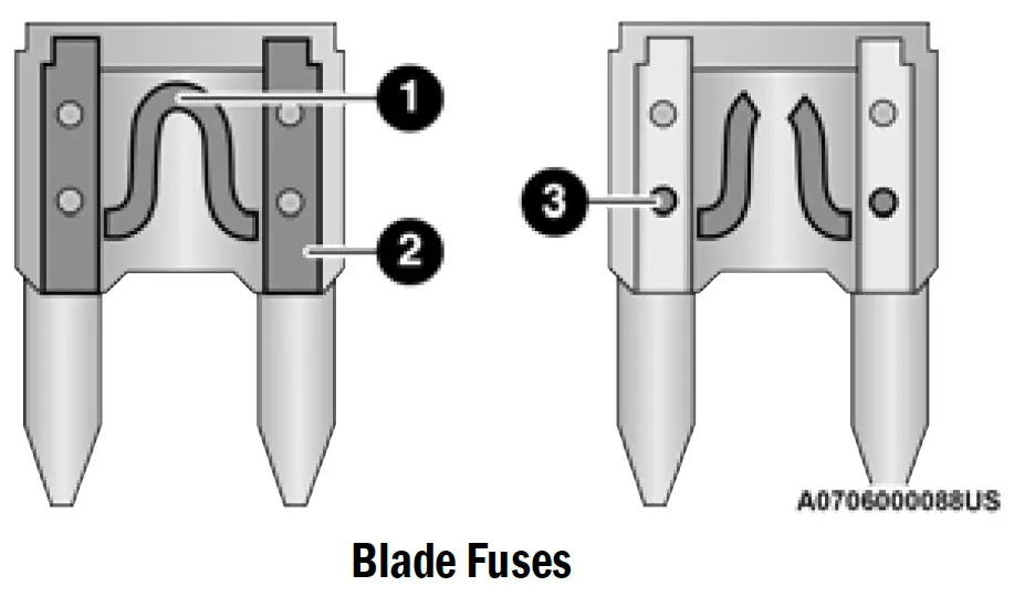
- Fuse Element
- Blade Fuse with a good/functional fuse element
- Blade fuse with a bad/not functional fuse element (blown fuse)
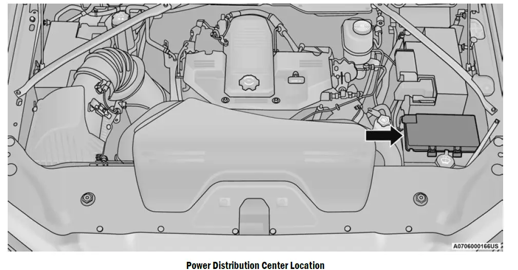
Underhood Fuses
The Front Power Distribution Center is located in the engine compartment. This module contains fuses and relays. Fuse cavity location and descriptions are printed on the inside of the power distribution center cover.
CAUTION!
- When installing the power distribution center cover, it is important to ensure the cover is properly positioned and fully latched. Failure to do so may allow water to get into the power distribution center and possibly result in an electrical system failure.
| Cavity | Cartridge Fuse | Micro Fuse | Description | |||||
| * If Equipped | ||||||||
| F01 | – | – | Spare | |||||
| F02 | 60 Amp Yellow | – | ABS Pump Mtr | |||||
| F03 | 60 Amp Yellow | – | Rad Fan HI / Lo * | |||||
| Cavity | Cartridge Fuse | Micro Fuse | Description | |||||
| F04 | 50 Amp Red | – | 400W Inverter | |||||
| F05 | 50 Amp Red | – | Air Suspension Comp | |||||
| F06 | 40 Amp Green | – | STOM | |||||
| F07 | 40 Amp Green | – | Starter Solenoid | |||||
| F08 | 20 Amp Blue | – | NOX Sensor * | |||||
| F09 | 30 Amp Pink | – | Gas – Brake Vacuum Pump * | |||||
| 40 Amp Green | Diesel – Fuel Heater * | |||||||
| F10 | 40 Amp Green | – | CBC #2 / Ext Lights | |||||
| F11 | 40 Amp Green | – | Brake SYS MOD ECU & Valves | |||||
| F12 | 40 Amp Green | – | CBC #3 / Pwr Locks | |||||
| F13 | 40 Amp Green | – | HVAC Blwr Mtr | |||||
| F14 | 40 Amp Green | – | CBC #4 / Ext Light | |||||
| F15 | 30 Amp Pink | – | Power Side Step * | |||||
| F16 | 30 Amp Pink | – | Smart – Bar Module * | |||||
| F17 | 30 Amp Pink | – | Winch * | |||||
| F18 | – | – | Spare | |||||
| F19 | 30 Amp Pink | – | Diesel SCR Feed * | |||||
| F20 | 30 Amp Pink | – | Passenger Door Mod | |||||
| F21 | 30 Amp Pink | – | DTCM | |||||
| F22 | 20 Amp Blue | – | Gas – ECM * | |||||
| 25 Amp White | Diesel – PCM * | |||||||
| F23 | 30 Amp Pink | – | CBC #1 / Int Light | |||||
| Cavity | Cartridge Fuse | Micro Fuse | Description | |||||
| * If Equipped | ||||||||
| F24 | 30 Amp Pink | – | Driver Door Mod | |||||
| F25 | 30 Amp Pink | – | FT Wiper | |||||
| F26 | – | – | Spare | |||||
| F27 | – | – | Spare | |||||
| F28 | 20 Amp Blue | – | TRLR Tow B / U | |||||
| F29 | 20 Amp Blue | – | TRLR Tow Park | |||||
| F30 | 30 Amp Pink | – | TRLR Tow | |||||
| F31 | – | – | Spare | |||||
| F32 | – | – | Spare | |||||
| F33 | 20 Amp Blue | – | Trans Control Mod * | |||||
| F34 | 30 Amp Pink | – | VSIM #2 * | |||||
| F35 | 30 Amp Pink | – | Sunroof * | |||||
| F36 | 30 Amp Pink | – | Rear Defroster (EBL) * | |||||
| F37 | 30 Amp Pink | – | Diesel Frame / Fuel HTR * | |||||
| F38 | 30 Amp Pink | – | ITBM * | |||||
| F39 | – | – | Spare | |||||
| F40 | – | 10 Amp Red | Vented Seats * | |||||
| F41 | – | 10 Amp Red | Act Grille Shutter / Dam * | |||||
| F42 | – | 20 Amp Yellow | Horn | |||||
| F43 | – | 15 Amp Blue | Heated Strng Wheel * | |||||
| F44 | – | 10 Amp Red | Diagnostic Port | |||||
| F45 | – | – | Spare | |||||
| Cavity | Cartridge Fuse | Micro Fuse | Description | |||||
| * If Equipped | ||||||||
| F46 | – | 10 Amp Red | Upfitters Relay Coils * | |||||
| F47 | – | – | Spare | |||||
| F48 | – | – | Spare | |||||
| F49 | – | 15 Amp Blue | IP Cluster / CSG | |||||
| F50 | – | 20 Amp Yellow | Air Suspension Mod * | |||||
| F51 | – | 10 Amp Red | IGN Mod / KINMod / RFHub | |||||
| F52 | – | 5 Amp Tan | Batt Snsr | |||||
| F53 | – | 20 Amp Yellow | TRLR Tow – Lt Turn/Stop | |||||
| F54 | – | 20 Amp Yellow | Non-Memory Adj Pedals * | |||||
| F55 | – | 10 Amp Red | Fwd Utility Lamps | |||||
| F56 | – | 10 Amp Red | VBV | |||||
| F57 | – | 20 Amp Yellow | TCM / PCM / Trans PRSR SW | |||||
| F58 | – | 10 Amp Red | Bed Lighting | |||||
| F59 | – | – | Spare | |||||
| F60 | – | – | Spare | |||||
| F61 | – | 10 Amp Red | NH3 Sensor / PM Sensor * | |||||
| F62 | – | 10 Amp Red | A/C Clutch | |||||
| F63 | – | 20 Amp Yellow | Ignition Coils / CAPS | |||||
| F64 | – | 25 Amp Clear | Fuel Injectors / PCM * | |||||
| F65 | – | 10 Amp Red | RVDMP / MOD BLE * | |||||
| F66 | – | 10 Amp Red | Sunroof / USB RR * / RR Mirror/ Passenger Wind SW | |||||
| F67 | – | 10 Amp Red | UCI / TRLR 360 Cam/ Tach * | |||||
BULB REPLACEMENT
Replacement Bulbs, Names, And Part Numbers
In the instance a bulb needs to be replaced, this section includes bulb description and replacement part numbers.
NOTE:
See an authorized dealer for LED bulb replacement.
| Interior Bulbs | |
| Bulb Name | Bulb Number |
| Overhead Console Lamps | TS 212–9 |
| Dome Lamp | 7679 |
| For lighted switches, see an authorized dealer for replacement instructions. | |
| Exterior Bulbs | |
| Bulb Name | Bulb Number |
| Low Beam (Halogen Reflector Headlamp) | H11LL |
| High Beam (Halogen Reflector Headlamp) | 9005LL |
| Low & High Beam | LED |
| Low & High Beam | LED |
| Turn Signal / Front Position (Halogen Reflector Headlamp) | 7444NA |
| Turn Signal | LED |
| Front Position (LED Headlamps) | LED |
| Front Side Marker (Headlamps) | LED |
| Front Fog Lamps (Halogen Reflector Headlamp) | H11LL |
| Exterior Bulbs | |
| Bulb Name | Bulb Number |
| Front Fog Lamps (LED Headlamps) | LED |
| Side Indicators (Front And Side View Mirror) | LED |
| Base Rear Tail/Turn and Stop Lamp | 3157K |
| Premium Rear Tail/Turn and Stop Lamp | LED |
| Base Tail/Backup Lamp | W21/5W |
| Center High Mounted Stop Lamp (CHMSL) | 921 |
| Cab Roof Marker Lamps | LED |
| Rear Lamp Bar ID Marker Lamp | LED |
| Side Marker Lamps (Dual Rear Wheels) | LED |
| Base Turn/Tail Lamp | PWY24W |
| Rear License Plate Lamp | LED |
Replacing Exterior Bulbs
BASE QUAD: LOW BEAM HEADLAMP, HIGH BEAM HEADLAMP, FRONT PARK AND TURN — IF EQUIPPED
Low Beam
See the following steps to replace:
- Open the hood.
- Disconnect and isolate the negative battery cable.
- Reach into the front wheel house ahead of the front wheel, remove the fastener, and lift the cover over the access hole in the front of the wheel house splash shield. Access to the rear of the lamp can be gained through this access hole.
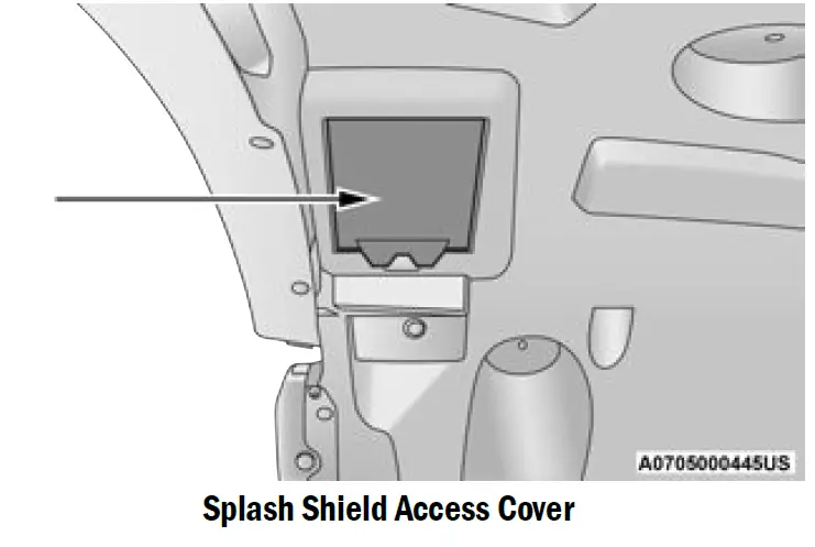
- Reach through the access hole of the wheel house splash shield and disengage the bulb access cover by rotating counterclockwise.
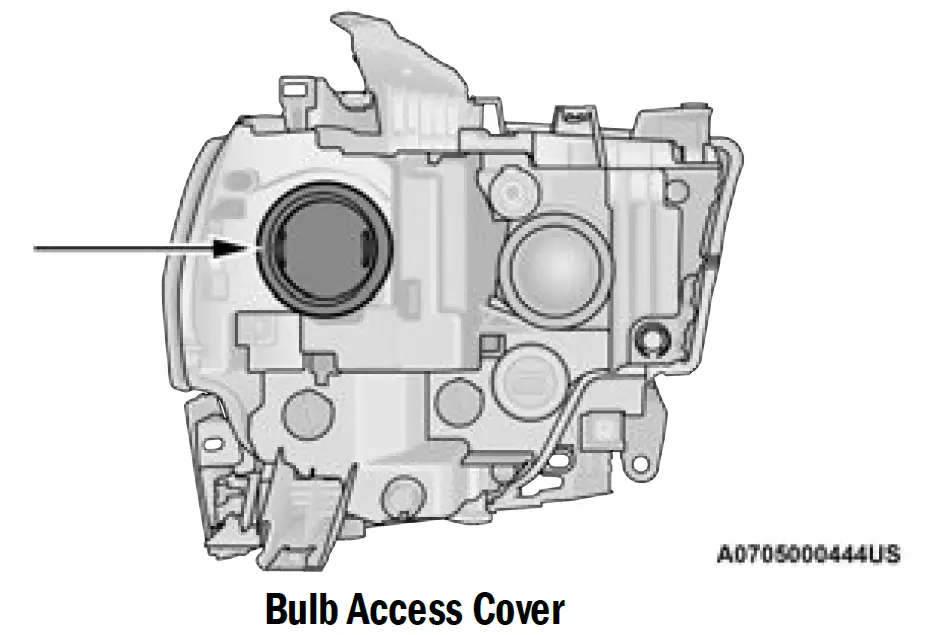
- Disconnect the internal lamp wiring harness connector from the low beam bulb.
CAUTION!- Do not contaminate the bulb glass by touching it with your fingers or by allowing it to contact other oily surfaces. Shortened bulb life will result.
- Always use the correct bulb size and type for replacement. An incorrect bulb size or type may overheat and cause damage to the lamp, the bulb socket, or the lamp wiring.
- Rotate the bulb counterclockwise a quarter turn to unlock the bulb from the lamp.
- Pull the bulb straight out from the housing.
- Reverse the procedure for installation of new bulb and covers.
High Beam
See the following steps to replace:
- Open the hood.
- Disconnect and isolate the negative battery cable.
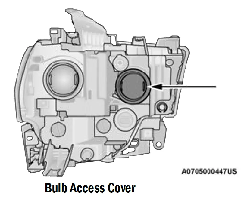
- Look under the hood and behind the headlamp to find the high beam bulb access cover.
- Reach behind the headlamp and disengage the access cover by rotating counterclockwise.
- Disconnect the internal lamp wiring harness connector from the high beam bulb.
CAUTION!- Do not contaminate the bulb glass by touching it with your fingers or by allowing it to contact other oily surfaces. Shortened bulb life will result.
- Always use the correct bulb size and type for replacement. An incorrect bulb size or type may overheat and cause damage to the lamp, the bulb socket, or the lamp wiring.
- Rotate the bulb counterclockwise a quarter turn to unlock the bulb from the lamp.
- Pull the bulb straight out from the housing.
- Reverse the procedure for installation of new bulb and covers.
Outer Front Park And Turn
See the following steps to replace:
- Open the hood.
- Disconnect and isolate the negative battery cable.
- Reach into the front wheel house ahead of the front wheel, remove the fastener, and lift the cover over the access hole in the front of the wheel house splash shield. Access to the rear of the lamp can be gained through this access hole.
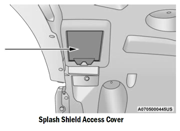
- Reach through the access hole of the wheel house splash shield and disengage the side marker socket by rotating counterclockwise a quarter turn.
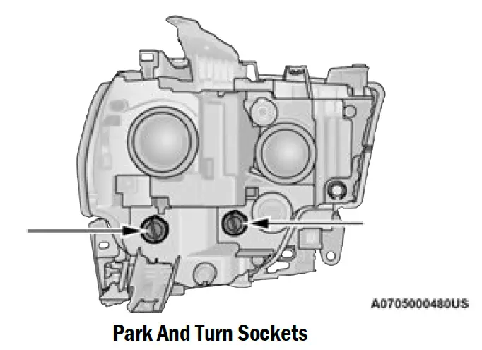
- Pull the socket and bulb straight out from the housing.
- Separate the bulb from the socket without twisting.
- Reverse the procedure for installation of new bulb and covers.
FOG LAMPS — IF EQUIPPED
Please see an authorized dealer for service on LED and Halogen front fog lamps.
Halogen
See the following steps to replace:
- Reach under and behind the front fascia/bumper to access the back of the front fog lamp housing.
- Disconnect the fog lamp wiring harness connector from the fog lamp bulb.
- Rotate the bulb counterclockwise a quarter turn to unlock the bulb from the housing.
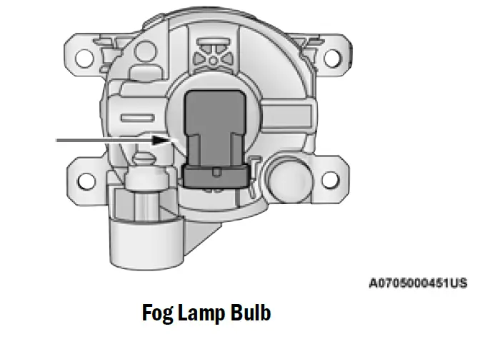
- Pull the bulb straight out from the housing.
CAUTION!
Do not contaminate the bulb glass by touching it with your fingers or by allowing it to contact other oily surfaces. Shortened bulb life will result.
REAR TAIL/STOP, TURN SIGNAL AND BACKUP LAMPS
See the following steps to replace:
- Remove the two screws and pushpins that pass through the bed sheet metal.
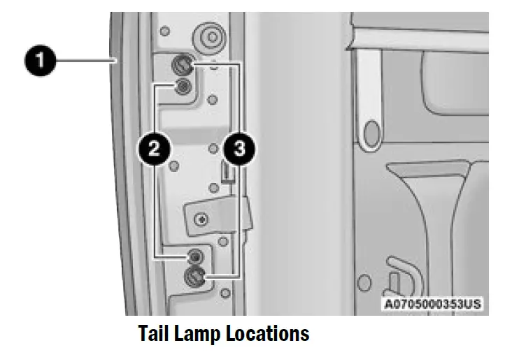
- Tail Lamp
- Screws
- Fasteners
- Pull the outboard side of the lamp rearward far enough to unsnap the two receptacles on the outboard side of the lamp housing from the two plastic snap post retainers in the outer box side panel.
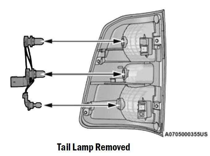
- Disconnect the wiring harness connectors from the bulb socket.
- Rotate the bulb socket counterclockwise a quarter turn to unlock it from the housing.
- Pull the bulb straight out of the socket.
CAUTION!
Do not contaminate the bulb glass by touching it with your fingers or by allowing it to contact other oily surfaces. Shortened bulb life will result. - Do not contaminate the bulb glass by touching it with your fingers or by allowing it to contact other oily surfaces. Shortened bulb life will result. housing.
CENTER HIGH MOUNTED STOP LAMP (CHMSL) WITH CARGO LAMP
See the following steps to replace:
- Remove the two screws holding the housing/lens to the body as shown.
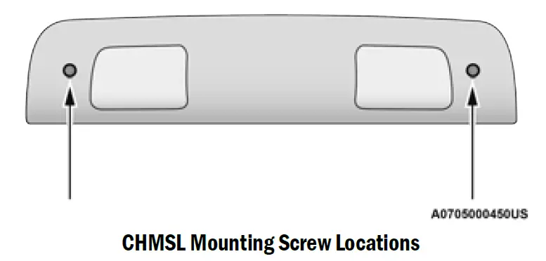
- Separate the connector holding the housing and wiring harness to the body.
- Turn the desired bulb socket a quarter turn and remove the socket and bulb from housing.
- Pull the desired bulb straight from the socket.
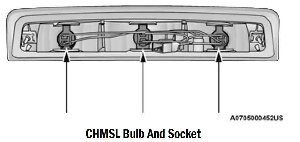 CAUTION!
Do not contaminate the bulb glass by touching it with your fingers or by allowing it to contact other oily surfaces. Shortened bulb life will result.- Outside Bulbs: Cargo Lamps
- Inside Bulb: Center High Mounted Stop Lamp
- Reverse the procedure for installation of bulbs and housing.
CAB TOP CLEARANCE LAMPS — IF EQUIPPED
See the following steps to replace:
- Remove the screws from the top of the lamp.
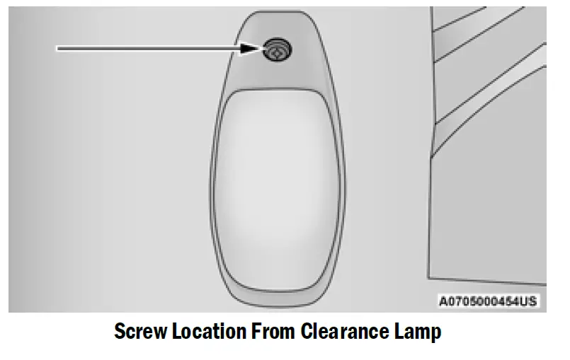
- Rotate the bulb socket a quarter turn and pull it from the lamp assembly.
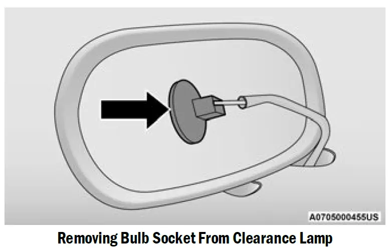
- Pull the bulb straight from it’s socket and replace.
REAR LAMP BAR ID MARKER (DUAL REAR WHEELS) — IF EQUIPPED
See the following steps to replace:
- Loosen the two screws and the housing to gain access to the bulb sockets.
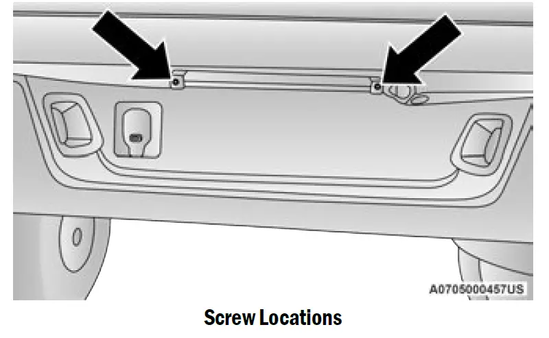
- Turn the socket a quarter turn counterclockwise to access the bulb.
- Pull the bulb straight out from the socket.
- Reverse the procedure for installation of the bulbs and housing.
SIDE MARKER LAMPS (DUAL REAR WHEELS) — IF EQUIPPED
See the following steps to replace: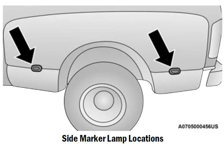
- Push rearward on the side marker lamp assembly.
- Pull the entire assembly from the fender.
- Turn the socket a quarter turn counterclockwise and remove from assembly to access the bulb.
- Pull the bulb straight out from socket.
- Reverse the procedure for installation of the bulbs and housing.
TIRES
TIRE SAFETY INFORMATION
Tire safety information will cover aspects of the following information: Tire Markings, Tire Identification Numbers, Tire Terminology and Definitions, Tire Pressures,
and Tire Loading.
Tire Markings 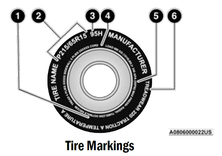
- US DOT Safety Standards Code (TIN)
- Size Designation
- Service Description
- Maximum Load
- Maximum Pressure
- Treadwear, Traction and Temperature Grades
NOTE:
- P (Passenger) — Metric tire sizing is based on US design standards. P-Metric tires have the letter “P” molded into the sidewall preceding the size designation. Example: P215/65R15 95H.
- European — Metric tire sizing is based on European design standards. Tires designed to this standard have the tire size molded into the sidewall beginning with the section width. The letter “P” is absent from this tire size designation. Example: 215/65R15 96H.
- LT (Light Truck) — Metric tire sizing is based on US design standards. The size designation for LT-Metric tires is the same as for P-Metric tires except for the letters “LT” that are molded into the sidewall preceding the size designation. Example: LT235/85R16.
- Temporary spare tires are designed for temporary emergency use only. Temporary high pressure compact spare tires have the letter “T” or “S” molded into the sidewall preceding the size designation.
Example: T145/80D18 103M. - High flotation tire sizing is based on US design standards and it begins with the tire diameter molded into the sidewall. Example: 31×10.5 R15 LT.
TIRE SIZING CHART
| EXAMPLE: |
| Example Size Designation: P215/65R15XL 95H, 215/65R15 96H, LT235/85R16C, T145/80D18 103M, 31×10.5 R15 LT |
| P = Passenger car tire size based on US design standards, or
“….blank ” = Passenger car tire based on European design standards, or LT = Light truck tire based on US design standards, or T or S = Temporary spare tire or 31 = Overall diameter in inches (in) 215, 235, 145 = Section width in millimeters (mm) 65, 85, 80 = Aspect ratio in percent (%) l Ratio of section height to section width of tire, or 10.5 = Section width in inches (in) |
| R = Construction code
l “R” means radial construction, or l “D” means diagonal or bias construction |
| 15, 16, 18 = Rim diameter in inches (in) |
| Service Description: |
| 95 = Load Index
l A numerical code associated with the maximum load a tire can carry |
| H = Speed Symbol
l A symbol indicating the range of speeds at which a tire can carry a load corresponding to its load index under certain operating conditions l The maximum speed corresponding to the speed symbol should only be achieved under specified operating conditions (i.e., tire pressure, vehicle loading, road conditions, and posted speed limits) |
| Load Identification:
Absence of the following load identification symbols on the sidewall of the tire indicates a Standard Load (SL) tire: l XL = Extra load (or reinforced) tire, or l LL = Light load tire or l C, D, E, F, G = Load range associated with the maximum load a tire can carry at a specified pressure |
| Maximum Load – Maximum load indicates the maximum load this tire is designed to carry |
| Maximum Pressure – Maximum pressure indicates the maximum permissible cold tire inflation pressure for this tire |
Tire Identification Number (TIN)
The TIN may be found on one or both sides of the tire; however, the date code may only be on one side. Tires with white sidewalls will have the full TIN, including the date code, located on the white sidewall side of the tire. Look for the TIN on the outboard side of black sidewall tires as mounted on the vehicle. If the TIN is not found on the outboard side, then you will find it on the inboard side of the tire.
| EXAMPLE: |
| DOT MA L9 ABCD 0301 |
| DOT = Department of Transportation
l This symbol certifies that the tire is in compliance with the US Department of Transportation tire safety standards and is approved for highway use |
| MA = Code representing the tire manufacturing location (two digits) |
| L9 = Code representing the tire size (two digits) |
| ABCD = Code used by the tire manufacturer (one to four digits) |
| 03 = Number representing the week in which the tire was manufactured (two digits)
l 03 means the 3rd week |
| 01 = Number representing the year in which the tire was manufactured (two digits)
l 01 means the year 2001 l Prior to July 2000, tire manufacturers were only required to have one number to represent the year in which the tire was manufactured. Example: 031 could represent the 3rd week of 1981 or 1991 |
Tire Terminology And Definitions
| Term | Definition |
| B-pillar | The vehicle B-pillar is the structural member of the body located behind the front door. |
|
Cold Tire Inflation Pressure |
Cold tire inflation pressure is defined as the tire pressure after the vehicle has not been driven for at least three hours, or driven less than 1 mile (1.6 km) after sitting for a minimum of three hours. Inflation pressure is measured in units of psi (pounds per square inch) or kPa (kilopascals). |
| Maximum Inflation Pressure | The maximum inflation pressure is the maximum permissible cold tire inflation pressure for this tire. The maximum inflation pressure is molded into the sidewall. |
| Recommended Cold Tire Inflation Pressure | Vehicle manufacturer’s recommended cold tire inflation pressure as shown on the tire placard. |
| Tire Placard | A label permanently attached to the vehicle describing the vehicle’s loading capacity, the original equipment tire sizes and the recommended cold tire inflation pressures. |
Tire Loading And Tire Pressure
NOTE:
The proper cold tire inflation pressure is listed on the driver’s side B-pillar or the rear edge of the driver’s side door.
Check the inflation pressure of each tire, including the spare tire (if equipped), at least monthly and inflate to the recommended pressure for your vehicle.
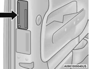
Example Tire Placard Location (Door)
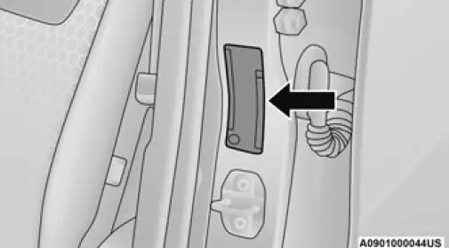
Example Tire Placard Location (B-pillar)
Tire And Loading Information Placard
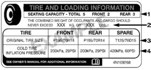
Tire And Loading Information Placard
This placard tells you important information about the:
- Number of people that can be carried in the vehicle.
- Total weight your vehicle can carry.
- Tire size designed for your vehicle.
- Cold tire inflation pressures for the front, rear, and spare tires.
Loading
The vehicle maximum load on the tire must not exceed the load carrying capacity of the tire on your vehicle. You will not exceed the tire’s load carrying capacity if you adhere to the loading conditions, tire size, and cold tire inflation pressures specified on the Tire and Loading Information placard page 203.
NOTE:
Under a maximum loaded vehicle condition, Gross Axle Weight Rating (GAWR) for the front and rear axles must not be exceeded.
For further information on GAWR, vehicle loading, and trailer towing page 203.
To determine the maximum loading conditions of your vehicle, locate the statement “The combined weight of occupants and cargo should never exceed XXX kg or XXX lbs” on the Tire and Loading Information placard. The combined weight of occupants, cargo/luggage and trailer tongue weight (if applicable) should never exceed the weight referenced here.
Steps For Determining Correct Load Limit
- Locate the statement “The combined weight of occupants and cargo should never exceed XXX kg or XXX lbs.” on your vehicle’s placard.
- Determine the combined weight of the driver and passengers that will be riding in your vehicle.
- Subtract the combined weight of the driver and passengers from XXX kg or XXX lbs.
- The resulting figure equals the available amount of cargo and luggage load capacity. For example, if “XXX” amount equals 1400 lbs. and there will be five 150 lb passengers in your vehicle, the amount of available cargo and luggage load capacity is 650 lbs.(1400-750 (5×150) = 650 lbs.)
- Determine the combined weight of luggage and cargo being loaded on the vehicle. That weight may not safely exceed the available cargo and luggage load capacity calculated in Step 4.
- If your vehicle will be towing a trailer, load from your trailer will be transferred to your vehicle. Consult this manual to determine how this reduces the available cargo and luggage load capacity of your vehicle.
Metric Example For Load Limit
For example, if “XXX” amount equals 635 kg and there will be five 68 kg passengers in your vehicle, the amount of available cargo and luggage load capacity is 295 kg (635-340 (5×68) = 295 kg) as shown in step 4.
NOTE:
- If your vehicle will be towing a trailer, load from your trailer will be transferred to your vehicle. The following table shows examples on how to calculate total load, cargo/luggage, and towing capacities of your vehicle with varying seating configurations and number and size of occupants. This table is for illustration purposes only and may not be accurate for the seating and load carry capacity of your vehicle.
- For the following example, the combined weight of occupants and cargo should never exceed 865 lbs (392 kg).
WARNING!
Overloading of your tires is dangerous. Overloading can cause tire failure, affect vehicle handling, and increase your stopping distance. Use tires of the recommended load capacity for your vehicle. Never overload them.
TIRES — GENERAL INFORMATION
Tire Pressure
Proper tire inflation pressure is essential to the safe and satisfactory operation of your vehicle. Four primary areas are affected by improper tire pressure:
- Safety
- Fuel Economy
- Tread Wear
- Ride Comfort and Vehicle Stability
Safety
WARNING!
- Improperly inflated tires are dangerous and can cause collisions.
- Underinflation increases tire flexing and can result in overheating and tire failure.
- Over inflation reduces a tire’s ability to cushion shock. Objects on the road and chuckholes can cause damage that result in tire failure.
- Overinflated or underinflated tires can affect vehicle handling and can fail suddenly, resulting in loss of vehicle control.
- Unequal tire pressures can cause steering problems. You could lose control of your vehicle.
- Unequal tire pressures from one side of the vehicle to the other can cause the vehicle to drift to the right or left.
- Always drive with each tire inflated to the recommended cold tire inflation pressure.
Both underinflation and over inflation affect the stability of the vehicle and can produce a feeling of sluggish response or over responsiveness in the steering.
NOTE:
- Unequal tire pressures from side to side may cause erratic and unpredictable steering response.
- Unequal tire pressure from side to side may cause the vehicle to drift left or right.
Fuel Economy
Underinflated tires will increase tire rolling resistance resulting in higher fuel consumption.
Tread Wear
Improper cold tire inflation pressures can cause abnormal wear patterns and reduced tread life, resulting in the need for earlier tire replacement.
Ride Comfort And Vehicle Stability
Proper tire inflation contributes to a comfortable ride. Over inflation produces a jarring and uncomfortable ride.
Tire Inflation Pressures
The proper cold tire inflation pressure is listed on the driver’s side B-pillar or rear edge of the driver’s side door.
At least once a month:
- Check and adjust tire pressure with a good quality pocket-type pressure gauge. Do not make a visual judgment when determining proper inflation. Tires may look properly inflated even when they are underinflated.
- Inspect tires for signs of tire wear or visible damage.
CAUTION!
After inspecting or adjusting the tire pressure, always reinstall the valve stem cap. This will prevent moisture and dirt from entering the valve stem, which could damage the valve stem.
Inflation pressures specified on the placard are always “cold tire inflation pressure”. Cold tire inflation pressure is defined as the tire pressure after the vehicle has not been driven for at least 3 hours, or driven less than 1 mile (1.6 km) after sitting for a minimum of 3 hours. The cold tire inflation pressure must not exceed the maximum inflation pressure molded into the tire sidewall. Check tire pressures more often if subject to a wide range of outdoor temperatures, as tire pressures vary with temperature changes.
Tire pressures change by approximately 1 psi (7 kPa) per 12°F (7°C) of air temperature change. Keep this in mind when checking tire pressure inside a garage, especially in the Winter.
Example: If garage temperature = 68°F (20°C) and the outside temperature = 32°F (0°C) then the cold tire inflation pressure should be increased by 3 psi (21 kPa), which equals 1 psi (7 kPa) for every 12°F (7°C) for this outside temperature condition.
Tire pressure may increase from 2 to 6 psi (13 to 40 kPa) during operation. DO NOT reduce this normal pressure build up or your tire pressure will be too low.
Tire Pressures For High Speed Operation
The manufacturer advocates driving at safe speeds and within posted speed limits. Where speed limits or conditions are such that the vehicle can be driven at high speeds, maintaining correct tire inflation pressure is very important. Increased tire pressure and reduced vehicle loading may be required for high-speed vehicle operation. Refer to an authorized tire dealer or original equipment vehicle dealer for recommended safe operating speeds, loading and cold tire inflation pressures.
WARNING!
High speed driving with your vehicle under maximum load is dangerous. The added strain on your tires could cause them to fail. You could have a serious collision. Do not drive a vehicle loaded to the maximum capacity at continuous speeds above 75 mph (120 km/h).
Radial Ply Tires
WARNING
Combining radial ply tires with other types of tires on your vehicle will cause your vehicle to handle poorly. The instability could cause a collision. Always use radial ply tires in sets of four. Never combine them with other types of tires.
Tire Repair
If your tire becomes damaged, it may be repaired if it meets the following criteria:
- The tire has not been driven on when flat.
- The damage is only on the tread section of your tire (sidewall damage is not repairable).
- The puncture is no greater than a ¼ of an inch (6 mm).
Consult an authorized tire dealer for tire repairs and additional information.
Damaged Run Flat tires, or Run Flat tires that have experienced a loss of pressure should be replaced immediately with another Run Flat tire of identical size and service description (Load Index and Speed Symbol). Replace the tire pressure sensor as well as it is not designed to be reused.
Run Flat Tires — If Equipped
Run Flat tires allow you the capability to drive 50 miles (80 km) at 50 mph (80 km/h) after a rapid loss of inflation pressure. This rapid loss of inflation is referred to as the Run Flat mode. A Run Flat mode occurs when the tire inflation pressure is of/or below 14 psi (96 kPa). Once a Run Flat tire reaches the Run Flat mode it has limited driving capabilities and needs to be replaced immediately. A Run Flat tire is not repairable. When a Run Flat tire is changed after driving with underinflated tire condition, please replace the TPMS sensor as it is not designed to be reused when driven under Run Flat mode 14 psi (96 kPa) condition.
NOTE:
TPMS sensor must be replaced after driving the vehicle on a flat tire condition.
It is not recommended driving a vehicle loaded at full capacity or to tow a trailer while a tire is in the Run Flat mode.
See the Tire Pressure Monitoring System section for more information.
Tire Spinning
When stuck in mud, sand, snow, or ice conditions, do not spin your vehicle’s wheels above 30 mph (48 km/h) or for longer than 30 seconds continuously without stopping.
For further information page 365.
WARNING!
Fast spinning tires can be dangerous. Forces generated by excessive wheel speeds may cause tire damage or failure. A tire could explode and injure someone. Do not spin your vehicle’s wheels faster than 30 mph (48 km/h) for more than 30 seconds continuously when you are stuck, and do not let anyone near a spinning wheel, no matter what the speed.
Tread Wear Indicators
Tread wear indicators are in the original equipment tires to help you in determining when your tires should be replaced.
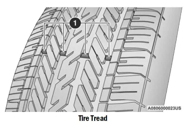
- Tread Wear Indicators
These indicators are molded into the bottom of the tread grooves. They will appear as bands when the tread depth becomes a 1/16 of an inch (1.6 mm). When the tread is worn to the tread wear indicators, the tire should be replaced.
Life Of Tire
The service life of a tire is dependent upon varying factors including, but not limited to:
- Driving style.
- Tire pressure – Improper cold tire inflation pressures can cause uneven wear patterns to develop across the tire tread. These abnormal wear patterns will reduce tread life, resulting in the need for earlier tire replacement.
- Distance driven.
- Performance tires, tires with a speed rating of V or higher, and Summer tires typically have a reduced tread life. Rotation of these tires per the vehicle scheduled maintenance is highly recommended.
WARNING!
Tires and the spare tire should be replaced after six years, regardless of the remaining tread. Failure to follow this warning can result in sudden tire failure. You could lose control and have a collision resulting in serious injury or death.
NOTE:
Wheel valve stem must be replaced as well when installing new tires due to wear and tear in existing tires.
Keep dismounted tires in a cool, dry place with as little exposure to light as possible. Protect tires from contact with oil, grease, and gasoline.
Replacement Tires
The tires on your new vehicle provide a balance of many characteristics. They should be inspected regularly for wear and correct cold tire inflation pressures. The manufacturer strongly recommends that you use tires equivalent to the originals in size, quality and performance when replacement is needed page 424. Refer to the Tire And Loading Information Placard or the Vehicle Certification Label for the size designation of your tire. The Load Index and Speed Symbol for your tire will be found on the original equipment tire sidewall.
See the Tire Sizing Chart example for more information relating to the Load Index and Speed Symbol of a tire page 416.
It is recommended to replace the two front tires or two rear tires as a pair. Replacing just one tire can seriously affect your vehicle’s handling. If you ever replace a wheel, make sure that the wheel’s specifications match those of the original wheels.
It is recommended you contact an authorized tire dealer or original equipment dealer with any questions you may have on tire specifications or capability. Failure to use equivalent replacement tires may adversely affect the safety, handling, and ride of your vehicle..
WARNING!
- Do not use a tire, wheel size, load rating, or speed rating other than that specified for your vehicle. Some combinations of unapproved tires and wheels may change suspension dimensions and performance characteristics, resulting in changes to steering, handling, and braking of your vehicle. This can cause unpredictable handling and stress to steering and suspension components. You could lose control and have a collision resulting in serious injury or death. Use only the tire and wheel sizes with load ratings approved for your vehicle.
- Never use a tire with a smaller load index or capacity, other than what was originally equipped on your vehicle. Using a tire with a smaller load index could result in tire over-loading and failure. You could lose control and have a collision.
- Failure to equip your vehicle with tires having adequate speed capability can result in sudden tire failure and loss of vehicle control.
CAUTION!
Replacing original tires with tires of a different size may result in false speedometer and odometer readings.
TIRE TYPES
All Season Tires — If Equipped
All Season tires provide traction for all seasons (Spring, Summer, Autumn, and Winter). Traction levels may vary between different all season tires. All season tires can be identified by the M+S, M&S, M/S or MS designation on the tire sidewall. Use all season tires only in sets of four; failure to do so may adversely affect the safety and handling of your vehicle.
Summer Or Three Season Tires — If Equipped
Summer tires provide traction in both wet and dry conditions, and are not intended to be driven in snow or on ice. If your vehicle is equipped with Summer tires, be aware these tires are not designed for Winter or cold driving conditions. Install Winter tires on your vehicle when ambient temperatures are less than 40°F (5°C) or if roads are covered with ice or snow. For more information, contact an authorized dealer. Summer tires do not contain the all season designation or mountain/snowflake symbol on the tire sidewall. Use Summer tires only in sets of four; failure to do so may adversely affect the safety and handling of your vehicle.
WARNING!
Do not use Summer tires in snow/ice conditions. You could lose vehicle control, resulting in severe injury or death. Driving too fast for conditions also creates the possibility of loss of vehicle control.
Snow Tires
Some areas of the country require the use of snow tires during the Winter. Snow tires can be identified by a “mountain/snowflake” symbol on the tire sidewall.
 If you need snow tires, select tires equivalent in size and type to the original equipment tires. Use snow tires only in sets of four; failure to do so may adversely affect the safety and handling of your vehicle.
Snow tires generally have lower speed ratings than what was originally equipped with your vehicle and should not be operated at sustained speeds over 75 mph (120 km/h). For speeds above 75 mph (120 km/h) refer to original equipment or an authorized tire dealer for recommended safe operating speeds, loading and cold tire inflation pressures.
While studded tires improve performance on ice, skid and traction capability on wet or dry surfaces may be poorer than that of non-studded tires. Some states prohibit studded tires; therefore, local laws should be checked before using these tire types.
SPARE TIRES — IF EQUIPPED
NOTE:
For vehicles equipped with Tire Service Kit instead of a spare tire, please refer to “Tire Service Kit” in “In Case Of Emergency” for further information.
CAUTION!
Because of the reduced ground clearance, do not take your vehicle through an automatic car wash with a compact or limited use temporary spare installed. Damage to the vehicle may result.
For restrictions when towing with a spare tire designated for temporary emergency use page 213.
Spare Tire Matching Original Equipped Tire And Wheel — If Equipped
Your vehicle may be equipped with a spare tire and wheel equivalent in look and function to the original equipment tire and wheel found on the front or rear axle of your vehicle. This spare tire may be used in the tire rotation for your vehicle. If your vehicle has this option, refer to an authorized tire dealer for the recommended tire rotation pattern.
Compact Spare Tire — If Equipped
The compact spare is for temporary emergency use only. You can identify if your vehicle is equipped with a compact spare by looking at the spare tire description on the Tire and Loading Information Placard located on the driver’s side door opening or on the sidewall of the tire. Compact spare tire descriptions begin with the letter “T” or “S” preceding the size designation. Example: T145/80D18 103M.
T, S = Temporary Spare Tire
Since this tire has limited tread life, the original equipment tire should be repaired (or replaced) and reinstalled on your vehicle at the first opportunity. Do not install a wheel cover or attempt to mount a conventional tire on the compact spare wheel, since the wheel is designed specifically for the compact spare tire.
Do not install more than one compact spare tire and wheel on the vehicle at any given time.
WARNING!
Compact and collapsible spares are for temporary emergency use only. With these spares, do not drive more than 50 mph
(80 km/h). Temporary use spares have limited tread life. When the tread is worn to the tread wear indicators, the temporary use spare tire needs to be replaced. Be sure to follow the warnings, which apply to your spare. Failure to do so could result in spare tire failure and loss of vehicle control.
Collapsible Spare Tire — If Equipped
The collapsible spare is for temporary emergency use only. You can identify if your vehicle is equipped with a collapsible spare by looking at the spare tire description on the Tire and Loading Information Placard located on the driver’s side door opening or on the sidewall of the tire.
Collapsible spare tire description example: 165/80-17 101P.
Since this tire has limited tread life, the original equipment tire should be repaired (or replaced) and reinstalled on your vehicle at the first opportunity.
Inflate collapsible tire only after the wheel is properly installed to the vehicle. Inflate the collapsible tire using the electric air pump before lowering the vehicle.
Do not install a wheel cover or attempt to mount a conventional tire on the collapsible spare wheel, since the wheel is designed specifically for the collapsible spare tire.
WARNING!
Compact and Collapsible spares are for temporary emergency use only. With these spares, do not drive more than 50 mph
(80 km/h). Temporary use spares have limited tread life. When the tread is worn to the tread wear indicators, the temporary use spare tire needs to be replaced. Be sure to follow the warnings, which apply to your spare. Failure to do so could result in spare tire failure and loss of vehicle control.
Full Size Spare — If Equipped
The full size spare is for temporary emergency use only. This tire may look like the originally equipped tire on the front or rear axle of your vehicle, but it is not. This spare tire may have limited tread life. When the tread is worn to the tread wear indicators, the temporary use full size spare tire needs to be replaced. Since it is not the same as your original equipment tire, replace (or repair) the original equipment tire and reinstall on the vehicle at the first opportunity.
Limited Use Spare — If Equipped
The limited use spare tire is for temporary emergency use only. This tire is identified by a label located on the limited use spare wheel. This label contains the driving limitations for this spare. This tire may look like the original equipped tire on the front or rear axle of your vehicle, but it is not. Installation of this limited use spare tire affects vehicle handling. Since it is not the same as your original equipment tire, replace (or repair) the original equipment tire and reinstall on the vehicle at the first opportunity.
WARNING!
Limited use spares are for emergency use only. Installation of this limited use spare tire affects vehicle handling. With this tire, do not drive more than the speed listed on the limited use spare wheel. Keep inflated to the cold tire inflation pressures listed on your Tire and Loading Information Placard located on the driver’s side B-pillar or the rear edge of the driver’s side door. Replace (or repair) the original equipment tire at the first opportunity and reinstall it on your vehicle. Failure to do so could result in loss of vehicle control.
WHEEL AND WHEEL TRIM CARE
All wheels and wheel trim, especially aluminum and chrome plated wheels, should be cleaned regularly using mild (neutral Ph) soap and water to maintain their luster and to prevent corrosion. Wash wheels with the same soap solution recommended for the body of the vehicle and remember to always wash when the surfaces are not hot to the touch.
Your wheels are susceptible to deterioration caused by salt, sodium chloride, magnesium chloride, calcium chloride, etc., and other road chemicals used to melt ice or control dust on dirt roads. Use a soft cloth or sponge and mild soap to wipe away promptly. Do not use harsh chemicals or a stiff brush. They can damage the wheel’s protective coating that helps keep them from corroding and tarnishing.
CAUTION!
Avoid products or automatic car washes that use acidic solutions or strong alkaline additives or harsh brushes. Many aftermarket wheel cleaners and automatic car washes may damage the wheel’s protective finish. Such damage is not covered by the New Vehicle Limited Warranty. Only car wash soap, Mopar® Wheel Cleaner or equivalent is recommended.
When cleaning extremely dirty wheels including excessive brake dust, care must be taken in the selection of tire and wheel cleaning chemicals and equipment to prevent damage to the wheels. Mopar® Wheel Treatment or Mopar® Chrome Cleaner or their equivalent is recommended or select a non-abrasive, non-acidic cleaner for aluminum or chrome wheels.
CAUTION!
Do not use scouring pads, steel wool, a bristle brush, metal polishes or oven cleaner. These products may damage the wheel’s protective finish. Such damage is not covered by the New Vehicle Limited Warranty. Only car wash soap, Mopar® Wheel Cleaner or equivalent is recommended.
NOTE:
If you intend parking or storing your vehicle for an extended period after cleaning the wheels with wheel cleaner, drive your vehicle and apply the brakes to remove the water droplets from the brake components.
This activity will remove the red rust on the brake rotors and prevent vehicle vibration when braking.
Dark Vapor Chrome, Black Satin Chrome, or Low Gloss Clear Coat Wheels
CAUTION!
If your vehicle is equipped with these specialty wheels, DO NOT USE wheel cleaners, abrasives, or polishing compounds. They will permanently damage this finish and such damage is not covered by the New Vehicle Limited Warranty. HAND WASH ONLY USING MILD SOAP AND WATER WITH A SOFT CLOTH. Used on a regular basis; this is all that is required to maintain this finish.
SNOW TRACTION DEVICES
Use of traction devices require sufficient
tire-to-body clearance. Due to limited clearance, the following snow traction devices are recommended. Follow these recommendations to guard against damage.
- Snow traction device must be of proper size for the tire, as recommended by the snow traction device manufacturer.
- No other tire sizes are recommended for use with the snow traction device.
- Please follow the table below for the recommended tire size, axle and snow traction device:
2500 4×2 (2WD)
Trim Level
Axle
Tire/Wheel Size
Snow Traction Device (Maximum Projection Beyond Tire Profile Or Equivalent)
Tradesman Rear
LT245/70R17E LT275/70R18E
U Class
Bighorn Laramie Longhorn
LT275/70R18E LT285/60R20E Limited LT285/60R20E
|
2500 4×4 (4WD) Trim Level |
Axle |
Tire/Wheel Size |
Snow Traction Device (Maximum Projection Beyond Tire Profile
Or Equivalent) |
| LT245/70R17E | |||
| Tradesman | LT285/70R17D | ||
| LT275/70R18E | |||
| Bighorn | |||
| Laramie
Limited |
Rear |
LT275/70R18E
LT285/60R20E |
U Class |
| Longhorn | |||
| LT285/70R17D | |||
| Power Wagon | LT275/70R18E | ||
| LT285/60R20E |
|
3500 SRW 4×2 (2WD) & 4×4 (4WD) Trim Level |
Axle |
Tire/Wheel Size |
Snow Traction Device (Maximum Projection Beyond Tire Profile
Or Equivalent) |
| Tradesman |
Rear |
LT275/70R18E |
U Class |
| Bighorn Limited Laramie
Longhorn |
LT275/70R18E LT285/60R20E |
|
3500 DRW 4×2 (2WD) Trim Level |
Axle |
Tire/Wheel Size |
Snow Traction Device (Maximum Projection Beyond Tire Profile
Or Equivalent) |
| Tradesman
Bighorn |
Rear | LT235/80R17E | U Class |
| Limited Laramie
Longhorn |
Front/Rear |
LT235/80R17E |
U Class |
|
3500 DRW 4×4 (4WD) Trim Level |
Axle |
Tire/Wheel Size |
Snow Traction Device (Maximum Projection Beyond Tire Profile
Or Equivalent) |
| Tradesman Bighorn Limited Laramie
Longhorn |
Front/Rear |
LT235/80R17E |
U Class |
WARNING!
Using tires of different size and type (M+S, Snow) between front and rear axles can cause unpredictable handling. You could lose control and have a collision.
CAUTION!
To avoid damage to your vehicle or tires, observe the following precautions:
- Because of restricted traction device clearance between tires and other suspension components, it is important that only traction devices in good condition are used. Broken devices can cause serious damage. Stop the vehicle immediately if noise occurs that could indicate device breakage. Remove the damaged parts of the device before further use.
- Install device as tightly as possible and then retighten after driving about ½ mile (0.8 km). Auto sock traction devices do not require retightening.
- Do not exceed 30 mph (48 km/h).
- Drive cautiously and avoid severe turns and large bumps, especially with a loaded vehicle.
- Do not drive for a prolonged period on dry pavement.
- Observe the traction device manufacturer’s instructions on the method of installation, operating speed, and conditions for use. Always use the suggested operating speed of the device manufacturer’s if it is less than 30 mph (48 km/h).
- Do not use traction devices on a compact spare tire.
TIRE ROTATION RECOMMENDATIONS
Tires on the front and rear axles of vehicles operate at different loads and perform different steering, driving, and braking functions. For these reasons, they wear at unequal rates.
These effects can be reduced by timely rotation of tires. The benefits of rotation are especially worthwhile with aggressive tread designs such as those on all season type tires. Rotation will increase tread life, help to maintain mud, snow and wet traction levels, and contribute to a smooth, quiet ride.
For the proper maintenance intervals page 369. The reasons for any rapid or unusual wear should be corrected prior to rotation being performed.
The suggested rotation method is the “rearward cross” shown in the following diagram. This rotation pattern does not apply to some directional tires that must not be reversed.
Tire Rotation (Rearward Cross)
Dual Rear Wheels — If Equipped
The tires used on dual wheel assemblies should be matched for wear to prevent overloading one tire in a set. To check if tires are even, lay a straight edge across all four tires. The straight edge should touch all the tires.
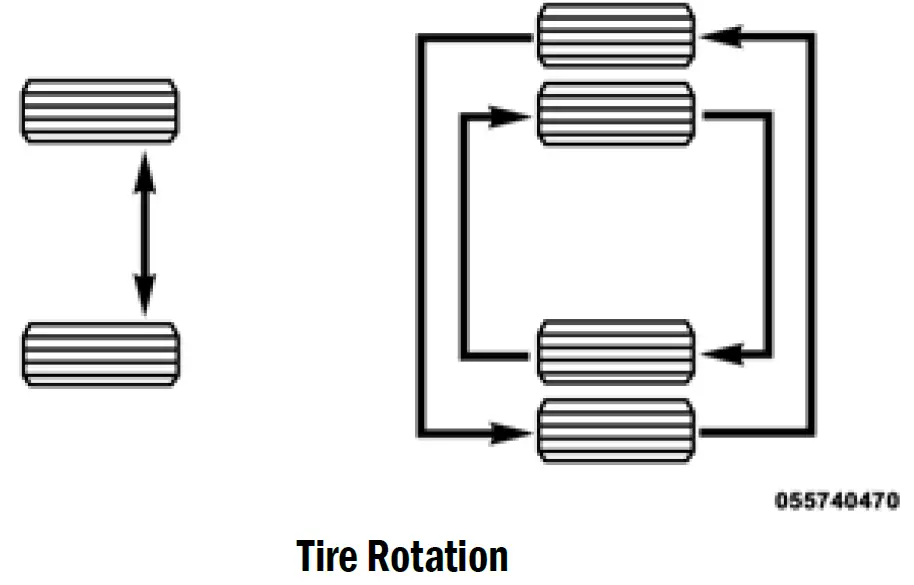 NOTE:
NOTE:
If your vehicle is equipped with a Tire Pressure Information System (TPIS):
- The Tire Pressure Information System (TPIS) uses unique sensors in the inner rear wheels to help identify them from the outer rear wheels, because of this, the inner and outer wheel locations can’t be switched.
After a tire rotation is completed, as shown, the system can auto learn the locations of each sensor ID. Auto learning/localization occurs when the vehicle ignition status is changed from Off to On and speeds of greater than 5 mph (8km/h) are obtained and remain over 5 mph (8km/h) for at about a 15 minute period. You may need to drive for 20 minutes to account slower speeds and stops. - If the tires are rotated incorrectly, The auto localization of the TPIS sensors will fail to locate correctly resulting in incorrect locations for the pressure values displayed in the instrument cluster.
CAUTION!
- 3500 Dual Rear Tires may only have one approved direction of rotation. This is to accommodate the asymmetrical design (tread pattern) of the
On/Off-Road tire and the use of Outline White Letter (OWL) tires.
When replacing a flat, the spare tire may have to be remounted on the rim, or installed at a different loca-tion, to maintain the correct placement of the tire on the wheel relative to the tire/wheel position on the truck. For example, if the spare is used to replace an outer rear tire it will have to be remounted on the rim so that the wheel is dished inward. That way the tread design of asymmetrical tires and the white writing of the OWL tires will maintain proper position.
DEPARTMENT OF TRANSPORTATION UNIFORM TIRE QUALITY GRADES
The following tire grading categories were established by the National Highway Traffic Safety Administration. The specific grade rating assigned by the tire’s manufacturer in each category is shown on the sidewall of the tires on your vehicle.
All passenger vehicle tires must conform to Federal safety requirements in addition to these grades.
TREADWEAR
The Treadwear grade is a comparative rating, based on the wear rate of the tire when tested under controlled conditions on a specified government test course. For example, a tire graded 150 would wear one and one-half times as well on the government course as a tire graded 150. The relative performance of tires depends upon the actual conditions of their use, however, and may depart significantly from the norm due to variations in driving habits, service practices, and differences in road characteristics and climate.
TRACTION GRADES
The Traction grades, from highest to lowest, are AA, A, B, and C. These grades represent the tire’s ability to stop on wet pavement, as measured under controlled conditions on specified government test surfaces of asphalt and concrete. A tire marked C may have poor traction performance.
WARNING!
The traction grade assigned to this tire is based on straight-ahead braking traction tests, and does not include acceleration, cornering, hydroplaning, or peak traction characteristics.
TEMPERATURE GRADES
The Temperature grades are A (the highest), B, and C, representing the tire’s resistance to the generation of heat and its ability to dissipate heat, when tested under controlled conditions on a specified indoor laboratory test wheel.
Sustained high temperature can cause the material of the tire to degenerate and reduce tire life, and excessive temperature can lead to sudden tire failure. The grade C corresponds to a level of performance, which all passenger vehicle tires must meet under the Federal Motor Vehicle Safety Standard No. 109. Grades B and A represent higher levels of performance on the laboratory test wheel, than the minimum required by law.
WARNING!
The temperature grade for this tire is established for a tire that is properly inflated and not overloaded. Excessive speed, underinflation, or excessive loading, either separately or in combination, can cause heat buildup and possible tire failure.
STORING THE VEHICLE
If you are storing your vehicle for more than three weeks, we recommend that you take the following steps to minimize the drain on your vehicle’s battery:
Disconnect the negative cable from the battery.
Anytime you store your vehicle, or keep it out of service (e.g., vacation) for two weeks or more, run the air conditioning system at idle for about five minutes in the fresh air and high blower setting. This will ensure adequate system lubrication to minimize the possibility of compressor damage when the system is started again.
- Disconnect the negative cable from battery.
Any time you store your vehicle or keep it out of service (i.e., vacation) for two weeks or more, run the air conditioning system at idle for about five minutes in the fresh air and high blower setting. This will ensure adequate system lubrication to minimize the possibility of compressor damage when the system is started again.
BODYWORK
PROTECTION FROM ATMOSPHERIC
AGENTS
Vehicle body care requirements vary according to geographic locations and usage. Chemicals that make roads passable in snow and ice and those that are sprayed on trees and road surfaces during other seasons are highly corrosive to the metal in your vehicle. Outside parking, which exposes your vehicle to airborne contaminants, road surfaces on which the vehicle is operated, extreme hot or cold weather and other extreme conditions will have an adverse effect on paint, metal trim, and underbody protection.
The following maintenance recommendations will enable you to obtain maximum benefit from the corrosion resistance built into your vehicle.
What Causes Corrosion?
Corrosion is the result of deterioration or removal of paint and protective coatings from your vehicle.
The most common causes are:
- Road salt, dirt and moisture accumulation.
- Stone and gravel impact.
- Insects, tree sap and tar.
- Salt in the air near seacoast localities.
- Atmospheric fallout/industrial pollutants.
BODY AND UNDERBODY MAINTENANCE
Cleaning Headlights
Your vehicle is equipped with plastic headlights and fog lights that are lighter and less susceptible to stone breakage than glass headlights.
Plastic is not as scratch resistant as glass and therefore different lens cleaning procedures must be followed.
To minimize the possibility of scratching the lenses and reducing light output, avoid wiping with a dry cloth. To remove road dirt, wash with a mild soap solution followed by rinsing.
Do not use abrasive cleaning components, solvents, steel wool or other aggressive material to clean the lenses.
PRESERVING THE BODYWORK
Washing
- Wash your vehicle regularly. Always wash your vehicle in the shade using Mopar® Car Wash, or a mild car wash soap, and rinse the panels completely with water.
- If insects, tar, or other similar deposits have accumulated on your vehicle, use Mopar® Super Kleen Bug and Tar Remover to remove.
- Use a high quality cleaner wax, such as Mopar® Cleaner Wax to remove road film, stains and to protect your paint finish. Use precautions to not scratch the paint.
- Avoid using abrasive compounds and power buffing that may diminish the gloss or thin out the paint finish.
CAUTION!
- Do not use abrasive or strong cleaning materials such as steel wool or scouring powder that will scratch metal and painted surfaces.
- Use of power washers exceeding 1,200 psi (8,274 kPa) can result in damage or removal of paint and decals.
Special Care
- If you drive on salted or dusty roads or if you drive near the ocean, hose off the undercarriage at least once a month.
- It is important that the drain holes in the lower edges of the doors, rocker panels, and trunk be kept clear and open.
- If you detect any stone chips or scratches in the paint, touch them up immediately.
- If your vehicle is damaged due to a collision or similar cause that destroys the paint and protective coating, have your vehicle repaired as soon as possible.
- If you carry special cargo such as chemicals, fertilizers, deicer salt, etc., be sure that such materials are well packaged and sealed.
- If a lot of driving is done on gravel roads, consider mud or stone shields behind each wheel.
- Use Mopar® Touch Up Paint on scratches as soon as possible. An authorized dealer has touch up paint to match the color of your vehicle.
INTERIORS
SEATS AND FABRIC PARTS
Use Mopar® Total Clean to clean fabric upholstery and carpeting.
WARNING!
Do not use volatile solvents for cleaning purposes. Many are potentially flammable, and if used in closed areas they may cause respiratory harm.
Seat Belt Maintenance
Do not bleach, dye, or clean the belts with chemical solvents or abrasive cleaners. This will weaken the fabric.
If the belts need cleaning, use Mopar® Total Clean, a mild soap solution, or lukewarm water. Do not remove the belts from the vehicle to wash them. Dry with a soft cloth.
Sun damage can also weaken the fabric. Replace the belts if they appear frayed or worn or if the buckles do not work properly.
WARNING!
A frayed or torn seat belt could rip apart in a collision and leave you with no protection. Inspect the seat belt system periodically, checking for cuts, frays, or loose parts. Damaged parts must be replaced immediately. Do not disassemble or modify the seat belt system. If your vehicle is involved in a collision, or if you have questions regarding seat belt or retractor conditions, take your vehicle to an authorized FCA dealer or authorized FCA Certified Collision Care Program facility for inspection.
PLASTIC AND COATED PARTS
Use Mopar® Total Clean to clean vinyl upholstery.
CAUTION!
- Direct contact of air fresheners, insect repellents, suntan lotions, or hand sanitizers to the plastic, painted, or decorated surfaces of the interior may cause permanent damage. Wipe away immediately.
- Damage caused by these type of products may not be covered by your New Vehicle Limited Warranty.
Cleaning Plastic Instrument Cluster
Lenses
The lenses in front of the instruments in this vehicle are molded in clear plastic. When cleaning the lenses, care must be taken to avoid scratching the plastic.
Clean with a wet soft cloth. A mild soap solution may be used, but do not use high alcohol content or abrasive cleaners. If soap is used, wipe clean with a clean damp cloth. Dry with a soft cloth.
LEATHER SURFACES
Mopar® Total Clean is specifically recommended for leather upholstery.
Your leather upholstery can be best preserved by regular cleaning with a damp soft cloth. Small particles of dirt can act as an abrasive and damage the leather upholstery and should be removed promptly with a damp cloth. Stubborn soils can be removed easily with a soft cloth and Mopar® Total Clean. Care should be taken to avoid soaking your leather upholstery with any liquid. Please do not use polishes, oils, cleaning fluids, solvents, detergents, or ammonia-based cleaners to clean your leather upholstery.
NOTE:
If equipped with light colored leather, it tends to show any foreign material, dirt, and fabric dye transfer more so than darker colors. The leather is designed for easy cleaning, and the manufacturer recommends Mopar® total care leather cleaner applied on a cloth to clean the leather seats as needed.
CAUTION!
Do not use Alcohol and Alcohol-based and/or Ketone based cleaning products to clean leather upholstery, as damage to the upholstery may result.
GLASS SURFACES
All glass surfaces should be cleaned on a regular basis with Mopar® Glass Cleaner, or any commercial household-type glass cleaner. Never use an abrasive type cleaner. Use caution when cleaning the inside rear window equipped with electric defrosters or windows equipped with radio antennas. Do not use scrapers or other sharp instruments that may scratch the elements.
When cleaning the rear view mirror, spray cleaner on the towel or cloth that you are using. Do not spray cleaner directly on the mirror.
Reference Link
View Full PDF: Dodge Ram Pickup 2023 User Manual | Auto User Guide
Download Link: Owner’s Manuals & User Guides | Dodge